Multipool Tronic - Pump ESPA - Free user manual and instructions
Find the device manual for free Multipool Tronic ESPA in PDF.
| Product type | Horizontal multistage centrifugal pump |
| Brand | ESPA |
| Model | Multipool Tronic |
| Power supply | Single-phase with built-in thermal protection |
| Required electrical protection | Residual current device (1 fn=30 mA) and multipole disconnector |
| Electrical cable type | H07RN-F (if not supplied) |
| Timer functions | 8 automatic programs, manual ON/OFF mode, time/day display |
| Dry running protection | Water lack detection with stop and alarm |
| Backup autonomy in case of power outage | 24 hours (time and program retention) |
| Maximum water temperature | 35 °C |
| Water type | Clean water, free of suspended solids |
| Application | Pool filtration (do not use with swimmers) |
| Mounting | Solid horizontal base, anchored with ∅8 screws |
| Suction connection | Diameter equal to or larger than the port, minimum 2% upward slope |
| Discharge connection | Diameter equal or larger, do not let weight rest on the pump |
| Routine maintenance | No maintenance under normal conditions; drain during freezing periods |
| Prolonged storage | Disassemble and store in a dry, ventilated place |
| Repairs | Only by an Official Technical Service |
| Disposal | No toxic materials; selective disassembly possible |
Frequently Asked Questions - Multipool Tronic ESPA
User questions about Multipool Tronic ESPA
0 question about this device. Answer the ones you know or ask your own.
Ask a new question about this device
Download the instructions for your Pump in PDF format for free! Find your manual Multipool Tronic - ESPA and take your electronic device back in hand. On this page are published all the documents necessary for the use of your device. Multipool Tronic by ESPA.
USER MANUAL Multipool Tronic ESPA
natural_image
Technical line drawing of a mechanical pump or motor assembly (no text or symbols visible)MULTIPOOL PLUS
MULTIPOOL TRONIC
natural_image
Technical line drawing of a mechanical pump or motor assembly (no text or symbols visible)E Manual de instrucciones
GB Instruction manual
F Manuel d'instructions
D Gebrauchsanweisung
I Manuale d'istruzioni
P Manual de instruções
These symbols together with one of the words
"Danger" or "Warning" indicates the risk level deriving from failure to observe the prescribed safety precautions:

DANGER Wams that failure to observe the precautions Risk of involves a risk of electric shock. electrocution

DANGER Warns that failure to observe the precautions-involves a risk of damage to persons and/or things.

WARNING Wams that failure to observe the precautions involves the risk of damaging the pump and/or the plant.
1 - General information
Please observe the following instructions to achieve the best pump performance possible and a trouble free installation.
These pumps are designed to operate with clean water, free from particles in suspension and with a maximum temperature of 35 degrees centigrade.

WARNING. Correct pump operation is assured by following the instructions on installation and use.

DANGER. Failure to adhere to the instructions can result in premature failure of the pump and voiding of the warranty.

DANGER. Risk of electric shock. The pump must not be used in a pool when people are swimming.
2. Installation
2.1 - Fixing
The pump should be installed on a solid, horizontal base, secured by screws or bolts and using the existing holes in the mount (2 bolts/screws of 8 mm. ∅)
2.2 - Suction pipe assembly
The suction pipe, if longer than 7 meters, must be of the same or greater diameter than the pump inlet and installed in an upward inclination to prevent trapped air pockets forming.
The pump suction pipe should always be connected to the filter outlet. (See installation diagram).
2.3 Discharge pipe assembly
It is recommended to use pipes with a diameter equal or greater than the pump outlet. This will reduce loss of head caused by friction in longer pipe runs.
Pipework must be supported and not rest on the pump.
If a foot valve has not been installed it is recommended to fit a check valve to prevent accidental draining down of the system.
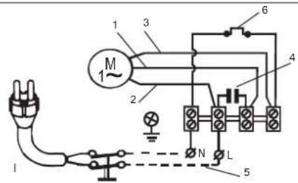
2.4 Electrical connection

The electrical installation must have a multi pole isolator with minimum 3 mm contact openings protected by a 30 ma. residual current detector (earth leakage trip).
Single phase motors have built-in thermal protection.
If the pump is not equipped with electric cable, an electrical engineer or a qualified technician must assemble this and it must also be of the type H07RN-F. Follow the instructions given on Fig. 1 for a correct electrical connection.
2.5 Pre-start checks

Ensure the voltage and frequency of the supply correspond to the values indicated on the electrical data label.
Ensure that the pump shaft is rotating freely.
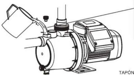
Fill the pump body with water through the self priming plug opening. If a foot valve has been installed, also fill the suction pipe.
Check all joints and connections for leaks.
THIS PUMP MUST NEVER BE DRY RUN.
3. Programming (Multipool Tronic)
3.1 - Programmer features
This programmer allows eight different programmes to be set for running the pump automatically; it can also work in manual mode, using ON/OFF.
The screen shows the current time and date. In the event of power-cut, the time/date and programme settings are retained in memory for 24 hours, although the screen remains blank.
There is also a safety function to prevent the pump running when there is no water.
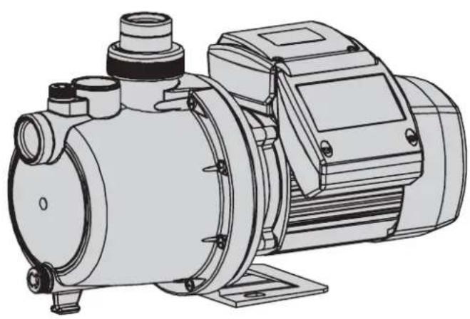
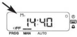
3.2 - Description of the front panel
text_image
Day of the week Pump operating status Automatic programme n° PROG MAN AUTO 00:00 Mn RESET • Time and date programming • Programme programming • Alarm Reset button OK Selection button Validation button Operating mode3.3 - Operation of the buttons
Select the menu with the Select button; from here, the desired values can be set. Use the OK button to confirm the menu to be altered and the values set.
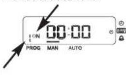
3.4 - Start function
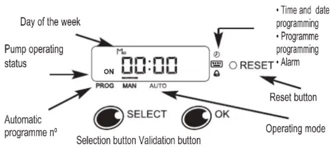
The first time the circuit is powered up, it is recommended that the reset button is pressed; this starts up the circuit afresh, deleting all programmes.
text_image
PROG MAN AUTO FlashlingPress the Select and OK buttons simultaneously and move on the next screen.
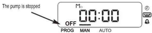
text_image
The pump is stopped OFF M₀ 00:00 PROG MAN AUTO3.5 - Operating mode
One of the menus is chosen with the Select button, while the OK button validates the choice for entering it. The menus available are:
- Manual operation
• Automatic operation - Current time and date setting
• Programming of automatic programmes
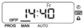
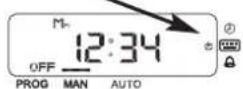
3.5.1 - Manual mode
First select the manual menu by activating the line above the word MANUAL. The pump is run or stopped using the OK button.
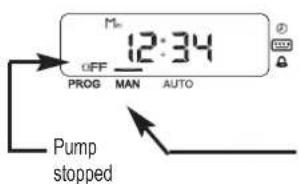
text_image
M= 12:34 OFF PROG MAN AUTO Pump stoppedPump running
Manual operation
text_image
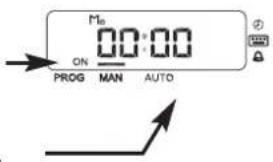
Mn ON 00:00 PROG MAN AUTO3.5.2 - Automatic mode
In automatic mode the pump starts and stops under the control of one of the 8 programmes.
To set automatic mode, follow the steps shown below:
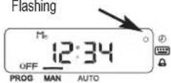
Press Select until the line
above
AUTO flashes

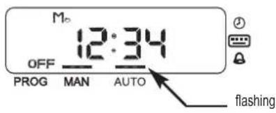
text_image
M 12:34 OFF PROG MAN AUTO flashing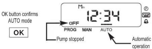
text_image
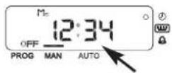
OK button confirms AUTO mode OK OFF PROG MAN AUTO Pump stopped Automatic operation3.5.3 - Setting current date and time
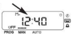
Press Select until the LED
beside the clock simbol flashes
Flashing
Confirm hour
programming
menu


Set the minutes

Confirm
the minutes

Set the times

Flashing
Confirm
the times

Flashing Select the day of the week

Confirm date and exit the menu

Once the day of the week
has been confirmed, exit from
the programming menu is automatic
If no key is pressed for more than 10 seconds, exit from the menu is automatic and no changes are saved.
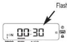
3.5.4 - Programming the automatic programmes
There are eight programmes, each with its start and stop time; the day of the week it is to operate can also be set, so that it could be one day, two days or every day, for example. A programme with no day set is a deactivated programme.
As an example, programme 1 will be programmed to start at 8:30 and end at 12:30 on Mondays, Wednesdays and Saturdays.
Select the programming menu

Flashing
Confirm the
programming
menu

Select the programme n°

Informs that it is start time
text_image
ON PROG MAN AUTOConfirm the
program
n^0

Set the start minutes

Confirm
the minutes

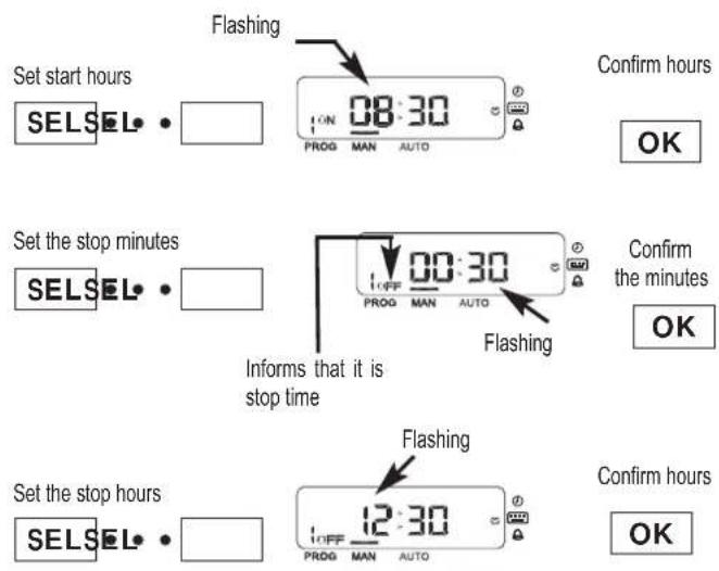
text_image
Set start hours SELSEL • Flashing ON 08:30 PROG MAN AUTO Confirm hours OK Set the stop minutes SELSEL • Informs that it is stop time OFF 00:30 PROG MAN AUTO Flashing Confirm the minutes OK Set the stop hours SELSEL • Flashing 12:30 PROG MAN AUTO Confirm hours OKNow select the days of the week. With the Select button, run through the various days, using the OK button to change the day's status from deactivated to activated or vice-versa; the day then moves forward one day.
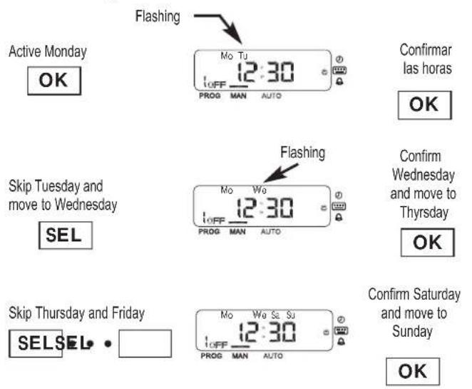
text_image
Active Monday OK Flashing Mo Tu 12:30 OFF PROG MAN AUTO Confirmar las horas OK Skip Tuesday and move to Wednesday SEL Flashing Mo We 12:30 OFF PROG MAN AUTO Confirm Wednesday and move to Thursday OK Skip Thursday and Friday SEL SEL • Mo We Sa Su 12:30 OFF PROG MAN AUTO Confirm Saturday and move to Sunday OKWhen Sunday is passed, the selected days flash. If any alteration is desired, press Select; if you wish to validate the set days, press OK.
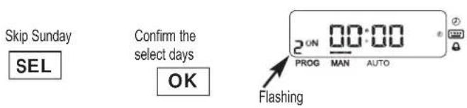
text_image
Skip Sunday SEL Confirm the select days OK 2 ON 00:00 PROG MAN AUTO FlashingAt this point programme no. 2 can be entered, or programming exited by leaving the buttons unpressed for 10 seconds.
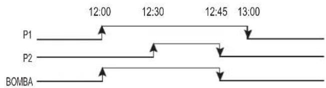
If there are overlapping programmes, the last one activated has the highest priority. Example: two programmes that activate on the same day as follows.
text_image
P1 12:00 12:30 12:45 13:00 P2 BOMBA3.6 - Deactivating a programme
To deactivate an automatic programme all the days of the week of the programme in question have to be deactivated.
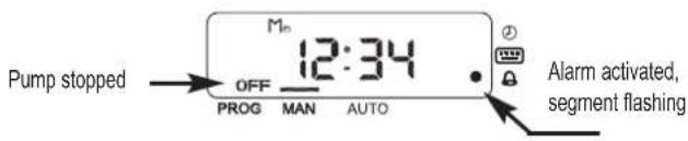
3.7 - Lack-of-water protection
The lack-of-water safety programme remains in operation whenever the pump is running. If the circuit detects that the pump has been running without any water for more than 10 seconds, the alarm is activated and the pump stops.
text_image
Pump stopped OFF 12:34 PROG MAN AUTO Alarm activated, segment flashingShould a voltage transient appear in the line while the pump is in operation, the alarm will be activated and the pump will stop. It will restart after 15 minutes.
3.8 - Unblocking the fault condition
To exit from the fault condition, press OK for more than 2 seconds. If the appliance is in automatic mode and the stop time arrives, the fault condition disappears.
In fault condition the circuit will try to start up again after 15 minutes; if it is not successful, further attempts will be made at 30 minutes, 45 minutes and 1 hour after the previous attempt. After this, no further attempts will be made.
4. Starting
Ensure all valves in the pipework are open.
Connect power supply. There will be a delay before water appears at the end of the discharge pipe.
If the pump fails to operate refer to the possible faults, causes and solutions list for assistance.

For the pump to work correctly, it is essential that the filter unit (recirculating pump) is also running.
5. Maintenance

Under normal conditions these pumps require no special or planned maintenance.
If the pump is not to be operated for a long period it is recommended to remove it from the installation, drain down and store in a dry, well ventilated place.
ATTENTION: In the event of faults or damage occurring to the pump, repairs should only be carried out by an authorised service agent. When the pump is eventually disposed of, please note that it contains no toxic or polluting material. All main components are material identified to allow selective disposal.
3 - Programmation (Multipool Tronic)
text_image
PROG MAN AUTO Intermittencetext_image
Technical cross-sectional diagram of a mechanical assembly with numbered components for identification.| E | GB | F | D | I | P |
| 1. Cuerpo bomba2. Rodete3. Difusor4. Retén mecánico5. Rodamiento6. Condensador7. Estator8. Eje motor9. Rodamiento | 1. Pump casing2. Impeller conector3. Diffuser4. Mechanical seal5. Anti-friction bearing6. Capacitor7. Stator8. Motor shaft9. Anti-friction bearing | 1. Corps de pompe2. Roue3. Diffuseur4. Garniture mécanique5. Roulement6. Condensateur7. Stator8. Arbre de moteur9. Roulement | 1. Pumpengehäuse2. Laufrad3. Leitrad4. Gleitringdichtung5. Wälzlager6. Kondensator7. Stator8. Motorwelle9. Wälzlager | 1. Corpo della pompa2. Girante3. Difusor4. Tenuta meccanica5. Tenuta meccanica6. Cusinetto a rotolamento7. Estator8. Albero del motore9. Tenuta meccanica | 1. Corpo de pompa2. Impulsor3. Difusor4. Fecho mecanico5. Rolamento6. Condensador7. Stator8. Veio de motor9. Rolamento |
ALIMENTACIÓN MONOFÁSICA SINGLE PHASE SUPPLY ALIMENTATION MONOPHASÉE EINPHASENSTROM ALIMENTAZIONE MONOFASICA ALIMENTAÇÃO MONOFASICA
text_image
1 3 M 1~ 2 6 4 N L 5 11 - ROJO RED ROUGE ROT ROSSO VERMELHO
2 - BLANCO WHITE BLANC WEISS BIANCO BRANCO
3 - NEGRO BLACK NOIR SCHWARZ NERO PRETO
4 - CONDENSADOR CAPACITOR CONDENSATEUR KONDENSATOR CONDENSATORE CONDENSADOR
5 - LÍNEA LINE TENSION SPANNUNG LINEA LINHA
6 - PROTECTOR TÉRMICO MOTOR RELAY PROTECTEUR MOTEUR MOTORSCHUTZ PROTETTORE DEL MOTORE MOTO PROTECTOR
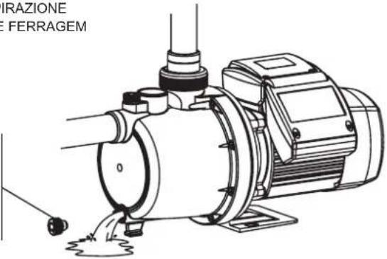
natural_image
Technical line drawing of an electric motor with pump and mounting bracket (no text or symbols)TAPÓN DE CEBADO PRIMING PLUG BOUCHON DE REMPLISSAGE EINFÜLLSTOPFEN TAPPO ASPIRAZIONE TAMPÃO DE FERRAGEM
TAPÓN DE VACIADO DRAINAGE PLUG BOUCHON DE VIDANGE ABLAßSTOPFEN TAPPO SCARICO TAMPÃO DE PURGA
text_image
GRAZIONE FERRAGEM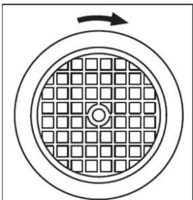
natural_image
Diagram of a circular structure with grid pattern and directional arrow (no text or symbols)Fig. 2
text_image
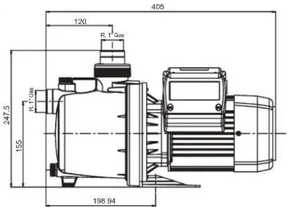
405 120 R. 1 Gas 247,5 R. 1 Gas 155 198 94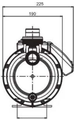
text_image
225 190| Q max.(l/min.) | H max.(m) | A 1~230V | C - μF | P1(kW) | IP | η (%) | Lpf | LwA (m) | LwA (g) | Kg |
| 84 | 55 | 6 | 16 | 1.3 | 55 | 32 | 60 | 72 | 75 | 12 |
V/Hz esp.: Ver placa datos bomba / See pump nameplate / Voir plaque signalétique / Siehe Pumpentypenschild / Vedere targhetta / Ver chapa de características da bomba
Temperatura líquido / Liquid Temperature / Température du liquide / Umgebungstemperatur / Temperatura del líquido / Temperatura do líquido:
4°C a 35°C
Temperatura de almacenamiento / Storage temperature / Température de stockage / Lagertemteratur / Temperatura ambiente / Temperatura ambiente: -10°C a +55°C Humedad relativa del aire / Relative Air Humidity / Humidité relative de l'air / Relative Luftfeuchtigkeit / Umidità relativa dell'aria / Humidade relativa do ar: 95% Max.
Lpf: Nivel presión acústica medido / Measured sound pressure level / Niveau pression acoustique mesuré / Gemessener Schalldruckpegel / Livello di pressione acustica misurato / Nivel pressão acústica medido
LWA (m): Nivel potencia acústica medido / Measured sound power level / Niveau puissance acoustique mesuré / Gemessener Schalleistungspegel / Livello di potenza acustica misurato / Nivel potência acústica medido
LWA (g): Nivel potencia acústica garantizado / Guaranteed sound power level / Niveau puissance acoustique garanti / Zugesicherter Schalleistungspegel / Livello di potenza acustica garantito / Nivel potência acústica garantido
Motor classe: I
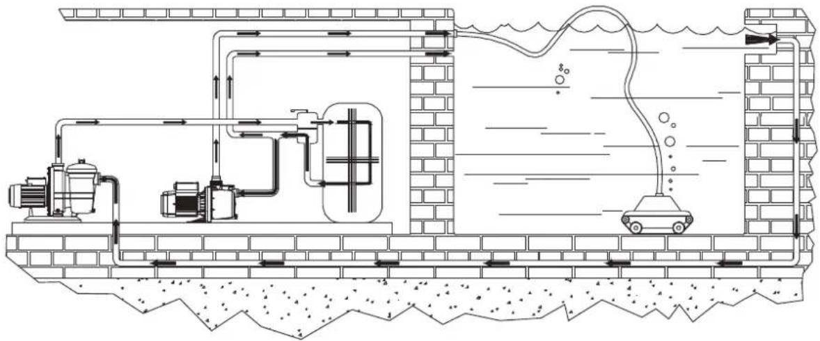
ESQUEMA DE INSTALACIÓN / INSTALLATION DIAGRAM / SCHÉMA D'INSTALLATION MONTAGEZEICHNUNG / SCHEMA DI INSTALLAZIONE / ESQUEMA DE INSTALAÇÃO
natural_image
Cross-sectional diagram of a water treatment facility showing pump, tank, and car (no text or labels)AJUSTE VÁLVULA IMPULSIÓN / ADJUSTING THE DISCHARGE VALVE RÉGLAGE DU CLAPET DE REFOULEMENT / EINSTELLUNG DRUCKVENTIL REGOLAZIONE VALVOLA DI MANDATA / AJUSTE DA VÁLVULA DE IMPULSÃO
When the valve is turned towards "-" it closes, less water passes through and a lower flow reaches the bottom-cleaner. At the same time, the pressure inside the pump body increases and the pressure gauge shows higher pressure = lower flow.
The opposite happens when the valve is turned in the direction of “+”: greater flow reaches the bottom-cleaner, the pressure inside the pump body decreases and the pressure gauge shows less pressure = greater flow. The output flow has to be regulated (using the valve) to the speed required by the cleaning robot. The pressure gauge mark allows the operating point to be memorised.
E
POSIBLES AVERÍAS, CAUSAS Y SOLUCIONES
GB
POSSIBLE FAULTS, CAUSES AND SOLUTIONS
| 21 | 3456 | CAUSE | SOLUTIONS | ||||
| × | × | Pump blocked | Disconnect it and take it to the official Technical Service | ||||
| × | Foot valve clogged | Clean it or replacet by new one | |||||
| × | × | Total manometric head higher than expected | Verify geometric head and loss of head | ||||
| × | × | × | Wrong tension | Check that the tension is the same as that on the technical characteristics label | |||
| × | × | × | Water level in well or tank has come down | Verify suction head | |||
| × | Fuse or thermal relai disconnected | Change fuse or thermal relai | |||||
| × | × | Impellers are worn out | Disconnect pump and take it to your Service Dealer | ||||
| × | × | Foot valve not submerged | Be sure suction pipe is submerged | ||||
| × | × | Pump was not primed | Fill pump body with water | ||||
| × | × | Room not properly aired | Provide good ventilation | ||||
| × | × | Air entry | Seal unions and joints properly |
POSSÍVEIS AVARIAS, CAUSAS E SOLUÇÕES
Safety instructions and damage prevention of pump and property.
D OBERFLÄCHENPUMPEN
text_image
Diagram showing a mechanical device with a rotating arrow and an open booklet labeled ABC, likely illustrating a mechanical or electrical process.GB Caution! Observe limitations of use.
GB The standard voltage must be the same as the mains voltage.
GB Connect pump to the mains via a omnipolar switch (that interrupts all the power supply wires) with at least 3 mm opening between contacts.
GB Remember to prime pump.
natural_image
Technical line drawing of a mechanical device with pipes and a motor (no text or symbols)6
E Asegúrese que el motor pueda autoventilarse.
GB Check for motor self-ventilation.
D Achten Sie auf die Eigenbelüftung des Motors!
F Contrôler que le moteur peut s'autoventiler.
I Assicuratevi che il motore possa autoventilarsi.
P Verifiquem que no motor possa funcionar a ventilação automática.
NL Zorg envoor dat de motor genoeg ventilatieruimte heeft.
natural_image
Diagram of a chemical reactor with labeled components and no readable text or symbols7
GB Beware of liquids and hazardous environments.
GB Install pump away from children's reach.
natural_image
Illustration of a person using a tool to interact with a device, crossed by diagonal lines (no text or symbols)9
GB Caution! Look out for accidental leaks. Do not expose pump to bad weather.
text_image
C O OFF 1010
GB Caution! Avoid icing. Cut out power supply before servicing pump.