USER MANUAL HF2417HTE Honda
thank you for having chosen one of our products. We hope you will be completely satisfied with your new ride-on lawnmower and that it will fully meet all your expectations.
This manual has been compiled in order that you may get to know your machine and to be able to use it safely and efficiently. Don't forget that it forms an integral part of the machine, so keep it handy so that it can be consulted at any time, and pass it on to the purchaser if you resell the machine.
This new machine of yours has been designed and made in line with current regulations, and is safe and reliable if used for cutting and collecting grass exactly following the instructions given in this manual (proper usage). Using the machine in any other way or ignoring the instructions for safe usage,
maintenance and repair is considered "incorrect usage" (1) which will invalidate the guarantee, and the manufacturer will decline all responsibility, placing the blame with the user for damage or injury to himself or others insuch cases.
Since the product is continually being improved, you may find slight differences between your machine and the descriptions contained in this manual. Certain modifications can be made to the machine without prior warning and without the obligation to update the manual, although the essential safety and function characteristics will remain unaltered. In case of any doubts, do not hesitate to contact your Dealer. And now enjoy your work!
After-sales Service
This manual provides all the necessary information to run the machine and for correct basic maintenance operations which can be performed by the user. Contact your Dealer for operations not described in this manual.

H|F|2|--|-|-|-|-|-
Write your machine's model here

Note your machine serial number here
HOW TO READ THE MANUAL
Some paragraphs in the manual contain important information regarding safety and operation and are emphasized in this manner:
NOTE
or important It gives details or further infor
mation on what has already been said, and aim to prevent damage to the machine.
WARNING!
Non-observance will result in the risk of injury to
oneself or others.
DANGER!
Non-observance will result in the risk of serious oneself or others.
The manual describes several machine models that can mainly differ in:
-type of transmission: with hydrostatic continuous speed adjustment.
particular fittings and/or attachments.
The symbol highlights all the differences in usage and is followed by the indication of the version to which it refers.
The symbol “ ” refers to another part of the manual where further information or clarification can be found.
NOTE
Whenever reference is made to a position on the ma
chine "front", "back", "left" or "right" side, this refers to the positions of the seated operator.
Honda France Manufacturing S.A.S.
All rights reserved 12-2019 Printed in Italy
HONDA
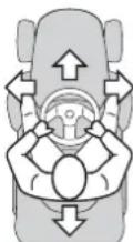
ORIGINAL INSTRUCTIONS
INSTRUCTION MANUAL
Ride-on lawnmower
HF2317·HF2417·HF2625
INDEX
- SAFETY REGULATIONS 2
Regulations for using the machine safely
- IDENTIFICATION OF THE MACHINE AND COMPONENTS 5
Explanations on how to identify the machine and its main components
3.UNPACKING AND ASSEMBLY 6
Explanations on how to remove the packing and on how to assemble separated parts
4.CONTROLS AND INSTRUMENTS 8
Position and functions of all the controls
- OPERATING INSTRUCTIONS 12
Provides indications for working efficiently and safely
5.1 Safety recommendations 12
5.2 Why the safety devices cut in 12
5.3 Preliminary operations before starting work 13
5.4 Using the machine 14
5.5 Using on slopes 17
5.6 Transport position 18
5.7 Advice on how to obtain a good cut 18
5.8 Summary of main steps to follow when using the machine 19
6.MAINTENANCE 19
All the information for maintaining the machine in peak ef
ficiency
6.1 Safety recommendations 19
6.2 Routine maintenance 20
6.3 Checks and adjustments 21
6.4 Dismantling and renewing parts 24
- TROUBLESHOOTING 27
A help in quickly resolving any problems
- ATTACHMENTS ON REQUEST 29
A description of the attachments available for particular types of work
- TECHNICAL SPECIFICATIONS 30
A summary of the main specifications of your machine
- ALPHABETICAL INDEX 31
Where information can be found
MAJOR HONDA DISTRIBUTOR ADDRESSES
"EC Declaration of Conformity"
CONTENT OUTLINE
1. SAFETY REGULATIONS
1.1 GENERAL SAFETY REGULATIONS
WARNING! READ THE INSTRUCTION BOOKLET THOR- OUGHLY BEFORE USING THE MACHINE. Keep for future reference.
A) TRAINING
1) WARNING! Read these instructions carefully before operating the machine. Become acquainted with the controls and the proper use of the machine. Learn how to stop the engine quickly. Failure to follow the warnings and instructions may result in fire and/or serious injury. Save all warnings and instructions for future reference.
2) Never allow children or persons unfamiliar with these instructions to use the machine. Local regulations may restrict the age of the operator.
3) Never mow while people, especially children, or pets are nearby.
4) Never use the machine if the user is tired or unwell, or has taken medicine, drugs, alcohol or any substances which may slow his reflexes and compromise his judgement.
5) Bear in mind that the operator or user is responsible for accidents or unexpected events occurring to other people or their property. It is the user's responsibility to assess the potential risk of the area where work is to be carried out, and to take all the necessary precautions to ensure his own safety and that of others, particularly on slopes or rough, slippery and unstable ground.
6) If the machine is sold or lent to others, make sure that the operator looks over the user instructions contained in this manual.
7) Do not allow children or other passengers to ride on the machine as they could fall off and injure themselves or compromise safe driving by the operator.
8) The machine operator must follow the driving instructions carefully and, in particular:
- Avoid distractions and maintain concentration whilst working;
- Bear in mind that control of a machine sliding on a slope will not be regained by the application of the brake. The main reasons for loss of control are:
Insufficient wheel grip;
- Excessive speed;
- Inadequate braking;
- Type of machine unsuitable for its task;
- Lack of knowledge about effects which may result from soil conditions, especially on slopes;
Incorrect use as a towing machine.
9) The machine is supplied with a series of micro-switches and safety devices which must never be tampered with or removed; this will invalidate the warranty and relieve the manufacturer from all responsibility. Always check that the safety devices are working properly before using the machine.
B) PRELIMINARY OPERATIONS
1) While using the machine, always wear anti-slip and resistant work footwear and long pants. Do not operate the machine when barefoot or wearing open sandals. Never wear scarves, shirts, necklaces, bracelets, clothing with flowing parts, laces or ties or any hanging or flapping accessory that could catch in the machine or in any objects or materials in the work area. Tie hair back if it is long. Wear hearing protection devices.
2) Use of hearing protections can reduce the ability to hear any warnings (shouting or alarms). Be careful of what occurs around you in the work area.
3) Thoroughly inspect the entire work area and remove anything that could be thrown by the machine or damage the cutting-means assembly or engine (stones, branches, iron wire, bones, etc.).
4) WARNING: DANGER! Petrol is highly flammable.
- Keep the fuel in approved containers, in a safe place, away from any naked lights or heat sources. Keep the containers out of the reach of children.
- Add fuel, using a funnel, only outdoors; do not smoke during this operation and each time fuel is handled;
- Top-up with fuel before igniting the engine; never remove the tank cap or add fuel while the engine is running or when it is hot;
If you have spilled some fuel, do not attempt to ignite the engine but move the machine away from the area of spillage and avoid creating any source of ignition until the fuel has evaporated and fuel vapours have dissipated;
- Always put the tank and fuel container caps back on and tighten well;
- Do not inhale fuel fumes.
- Open the fuel tank slowly to allow the pressure inside to decrease gradually.
-
Never start the machine in the same place in which you refilled it with fuel; the engine must be started in an area at least 3 metres from where you refuelled.
-
If fuel is spilt on clothing, change clothing before starting the engine.
5) Replace faulty silencers.
6) Before using the machine, check its general condition and in particular:
the appearance of the cutting means, and check that the screws and cutting-means assembly are not worn or damaged. Replace the entire cutting means and all damaged or worn screws to preserve balance. Any repairs must be done at a specialised centre.
7) Check the battery status regularly, and replace it if there is any damage to the casing, cover or terminals.
8) Before starting work, always fit the exit guards (grass catcher, rear discharge guard).
C) DURING USE
1) Do not operate the engine in a confined space where dangerous carbon monoxide fumes can develop. All starting operations have to be effected in an open or well ventilated area. Always remember that exhaust gases are toxic. When starting up the machine, do not direct the silencer and therefore the exhaust fumes towards flammable materials.
2) Work only in daylight or with good artificial light in good visibility conditions. Keep persons, children and animals away from the working area. Get another adult to keep the children under supervision.
3) Avoid working with wet grass, in the rain and when there is a risk of a thunderstorm, especially lightening.
4) Before igniting the engine, disengage the cutting means or the power socket and put the gear in neutral.
5) Pay special attention when approaching obstacles that could compromise visibility.
6) Engage the parking brake when parking the machine.
7) The machine must not be used on slopes of over 10^ (17%) , regardless of the mowing direction.
8) Remember there is no such thing as a "safe" slope. Driving on grass slopes requires particular care. To prevent overturning or loss of control over the machine:
- Do not stop or start suddenly when going up or downhill.
- Engage the drive slowly and always keep the machine in transmission, especially when travelling downhill;
- Machine speeds should be kept low on slopes and during tight turns;
- Watch out for humps, hollows and other hidden hazards;
- Never mow across the face of the slope. Lawns on a slope have to be mowed moving up and down and never across them. When changing direction, take great care that the wheels facing the slope do not hit any obstacles (such as stones, branches, roots, etc.) that may cause the machine to slide sideways, tip over or make you lose control.
9) Reduce speed before any change of direction on slopes, and always apply the parking brake before leaving the machine at a standstill and unattended.
10) Be very careful near ravines, ditches or embankments. The machine could overturn if a wheel slides over the edge or if the earth gives way.
11) Pay maximum attention when working in reverse gear. Look behind you to make sure there are no obstacles before and during operations in reverse gear.
12) Use care when pulling loads or using heavy equipment:
- Use approved drawbar hitch points only when towing.
- Limit loads to those you can safely control.
- Do not turn sharply. Take care when reversing;
- Use counterweight(s) or wheel weights whenever advised in the instructions manual.
13) Disengage the cutting means or the power socket when crossing areas with no grass, when moving to or from areas that require mowing, and move the cutting-means assembly to its highest position.
14) Pay attention to traffic when using the machine near roads.
15) WARNING! The machine has not been approved for use on public roads. It must be used (as indicated by the highway code) in private areas closed to traffic.
16) Never operate the machine with damaged, missing or incorrectly assembled guards (grass catcher, rear discharge guards).
17) Always keep hands and feet away from the cutting means, when starting and when using the machine. Attention: the cutting means will continue to rotate for a few seconds after disengagement or after you have switched off the engine. Keep away from the discharge opening.
18) Do not leave the machine stationary on high grass with the engine running to avoid the risk of starting a fire.
19) When using the attachments, never direct the opening towards people.
20) Use manufacturer-recommended attachments only.
21) Don't use the machine if the attachments/tools are not installed in their seats.
22) Pay attention when using the grass catcher and attachments that can alter the stability of the machine, especially on slopes.
23) Do not change the engine settings or over-rev the engine.
24) Do not touch the engine parts as they get very hot when running. Burns hazard.
25) Disengage the cutting means or power socket, put in neutral and engage the parking brake, turn off the engine and remove the ignition key (checking that all moving parts are completely stationary):
- Whenever the machine is left unattended or the operator dismounts from the driving seat:
Before clearing blockages or unclogging the discharge chute;
Before checking, cleaning or working on the machine;
- After striking a foreign object. Inspect the machine for damage and make repairs before using it again.
26) Disengage the cutting means or the power socket and switch off the engine (making sure that all moving parts are stationary):
-Beforerefuelling;
- Whenever you remove or reattach the grass catcher;
- Whenever you remove or reattach the discharge guard;
- Before adjusting the cutting height, if this operation can not be performed from the driving seat.
27) Disengage the cutting means or the power socket during transport and whenever it is not in use.
28) Reduce the throttle setting before stopping the engine. Shut off the fuel supply on completing the work, following the instructions in the engine manual.
29) Pay attention to cutting means assemblies with more than one cutting means, as a rotating cutting means can trigger the rotation of the others.
30) Never disengage, deactivate, remove or tamper with the safety systems/micro switches installed.
31) WARNING - If something breaks or an accident occurs whilst working, turn off the engine immediately and move the machine away to prevent further damage; if an accident occurs with injuries or third parties are injured, carry out the first aid measures most suitable for the situation immediately and contact the medical authorities for any necessary health care. Carefully remove any debris which could cause damage or injury to persons or animals if ignored.
32) WARNING - The noise and vibration levels shown in these instructions are the maximum levels for use of the machine. The use of an unbalanced cutting means, excessive speed of movement, or
lack of maintenance have a significant influence on noise emissions and vibrations. Consequently, it is necessary to take preventive steps to eliminate possible damage due to high levels of noise and stress from vibration. Maintain the machine well, wear ear protection devices, and take breaks while working.
33) Do not use USB accessories while cutting grass or driving.
1) WARNING! - Before cleaning or doing maintenance work, take out the ignition key and read the relevant instructions. Wear proper clothing and protective gloves whenever your hands are at risk.
2) WARNING! - Never use the machine with worn or damaged parts. Faulty or worn-out parts must always be replaced and never repaired. Use original replacement parts only: the use of non-original and/or incorrectly fitted parts will jeopardize the safety of the machine, may cause accidents or personal injuries for which the Manufacturer is under no circumstance liable or responsible.
3) Any adjustments or maintenance operations not described in this manual must be carried out by your Dealer or a specialized Service Centre with the necessary knowledge and equipment to ensure that the work is done correctly maintaining the machine's original safety level. Any operations performed in unauthorized centres or by unqualified persons will totally invalidate the Warranty and all obligations and responsibilities of the Manufacturer.
4) After each use, remove the ignition key and check for damage. 5) Keep all nuts, bolts and screws tight to be sure the equipment is in safe working condition. Routine maintenance is essential for safety and for maintaining a high performance level.
6) Check that the cutting means screws are properly tightened on a regular basis.
7) Wear work gloves when handling, disassembling and reassembling all cutting means.
8) Keep the cutting means well balanced during sharpening. All work on the cutting means (disassembly, sharpening, balancing, reassembly and/or replacing) are demanding jobs that require special skills as well as special tools. For safety reasons, these jobs are best carried out at a specialised centre.
9) Check that the brakes work properly on a regular basis. It is vital for brakes to undergo regular maintenance and, where necessary, repair work.
10) Check the side discharge guard, the discharge guard, the grass catcher and the intake grille frequently. Replace them if they are damaged.
11) Replace any instruction or warning message stickers, if damaged.
12) When the machine is to be stored or left unattended, lower the cutting-means assembly.
13) Store the machine out of the reach of children.
14) Do not store the machine with fuel in the tank in an area where the fuel vapours could reach an open flame, a spark or a strong heat source.
15) Allow the engine to cool down before storing in any enclosure.
16) To reduce fire hazards, keep the engine, silencer, battery compartment and petrol storage area free of grass, leaves, or excessive grease. Always empty the grass catcher and do not leave containers full of cut grass inside storage areas.
17) To reduce fire hazards, check there are no oil and/or fuel leaks on a regular basis.
18) If the fuel tank has to be emptied, this should be done outdoors once the engine has cooled down.
19) Never leave the keys in the ignition or within reach of children or unauthorised persons. Always remove the ignition key before doing any maintenance.
20) Be careful during adjustment of the machine to prevent entrapment of the fingers between moving parts of the cutting means and fixed parts of the machine.
E) TRANSPORT
1) WARNING! - If the machine must be transported on a truck or trailer, use ramps with suitable resistance, width and length. Load the machine with the engine switched off, without a driver and pushed by an adequate number of people. During transport, lower the cutting-means assembly or attachment, engage the parking brake, position the machine so that it can cause no danger to persons and fasten it firmly to the means of transport using ropes or chains to prevent it from tipping over causing damage and fuel leaks.
F) ENVIRONMENTAL PROTECTION
1) Environmental protection should be a priority of considerable importance when using the machine, for the benefit of both social coexistence and the environment in which we live. Avoid being a disturbance to the neighbourhood.
2) Scrupulously comply with local regulations and provisions for the disposal of packaging, oils, petrol, filters, damaged parts or any elements which have a strong impact on the environment; this waste must not be disposed of as normal waste, it must be separated and taken to specified waste disposal centres where the material will be recycled.
3) Scrupulously comply with local regulations for the disposal of waste materials after mowing.
4) At the time of decommissioning, do not pollute the environment with the machine, but hand it over to a disposal centre, in accordance with the local laws in force.
1.2 DESCRIPTION OF THE MACHINE AND ITS RANGE OF USE
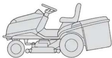
This machine is a garden tool and precisely a ride-on lawnmower with seated operator.
The machine is equipped with an engine which drives a cutting unit protected by a casing, as well as a transmission unit that moves the machine.
The operator is able to operate the machine and use the main controls, always seated in the operator's position.
The devices fitted on the machine stop the engine and the cutting means within a few seconds, should the operator behave in a manner that does not comply with the necessary safety precautions.
Intended use
This machine was designed and built to cut grass.
The use of special attachments provided for by the Manufacturer as original equipment or which may be purchased separately, allows this work to be done in various operating modes, illustrated in this manual or the instructions that accompany the single attachments. Likewise, the intended use can be extended to include other functions by applying supplementary attachments (if provided for by the Manufacturer), abiding by the restrictions and conditions indicated in the instructions accompanying the attachment.
User types
This machine is intended for use by consumers, i.e. novice and/or first time operators and not professionals. The machine is intended for "DIY" use only.
Improper use
Any other usage not in keeping with the above-mentioned ones may be hazardous and harm persons and/or damage things. Examples of improper use may include, but are not limited to:
- transporting people, children or animals on the machine or on a trailer;
-
towing or pushing loads without the use of the specified attachment for towing;
-
using the machine for riding over unstable, slippery, icy, stony, rough, marshy ground or puddles that do not allow the consistency of the ground to be assessed;
- using the cutting means on surfaces other than grass;
- using of the machine for leaf or debris collection.
Improper use of the machine will invalidate the warranty, relieve the Manufacturer from all liabilities, and the user will consequently be liable for all and any damage or injury to himself or others.
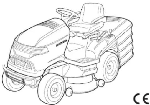
1.3 SAFETY LABELS
Your machine must be used with care. Therefore, labels have been placed on the machine to remind you pictorially of the main precautions to take during use. These labels are to be considered an integral part of the machine. If a label should fall off or become illegible, contact your Retailer to replace it. Their meaning is explained below.
1 = Warning: Read the instructions before operating the machine.
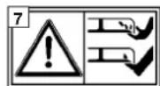
2 = Warning: Disconnect the key and read the instructions before carrying out any maintenance or repair work.
3 = Danger! Ejected objects: Do not operate without either the rear discharge guard or the grass catcher being in place.
4 = Danger! Ejected objects: Keep bystanders away.
5 = Danger! Machine rollover: Do not use this machine on slopes greater than 10^ .
6 = Danger! Dismemberment: Make sure that children stay clear of the machine all the time when engine is running.
6a = Do not climb onto the machine putting your feet on the cutting-means assembly.
7 = Danger of cutting yourself. Cutting means in motion. Do not put hands or feet near or under the opening of the cutting means housing.
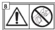
8= Warning: Never tamper the microswitch.
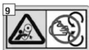
9 = Avoid injuries caused by moving belts: Never start up the machine without the safety guards in place. Keep a safe distance between you and the belts.

10=Warning: Read the instructions before operating the machine.
11=Warning: The engine releases carbon monoxide, which is a poisonous toxic gas. Do not run in confined space.
12=Warning: Gasoline is extremely flammable and explosive. Stop the engine and let it cool down before refuelling.
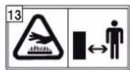
13=Warning: During operation, the muffler becomes very hot and remains hot for some time even after the engine has stopped.
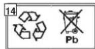
14 = This is a recyclable product. It contains lead. Do not discard it in the environment and dispose of in compliance with the laws in force.
151617181920


15 = Flammable vapours - Keep away from open flames.
16 = Wear protective goggles.
17 = Keep out of the reach of children.
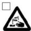
18 = Corrosive liquid. If the liquid comes into contact with the eyes, rinse immediately with water and call a physician.
19 = Read the instructions for use.
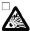
20 = Explosion risk.
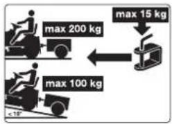
1.4 REGULATIONS FOR TOWING
A kit for towing a small trailer is available on request. This attachment must be fitted following the instructions provided.
When using the towing kit, do not exceed the recommended loads stated on the label and follow the safety instructions (1.2, C-6).
Total towable weight: on flat ground: 200 kg or less on a slope (10° or less): 100 kg or less
2. IDENTIFICATION OF THE MACHINE AND COMPONENTS
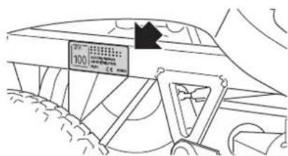
2.1 IDENTIFICATION OF THE MACHINE
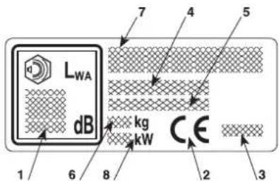
The information label, located on the left side of the chassis, has the essential data of each machine.
:
- Acoustic power level according to directive 2000/14/EC, 2005/88/EC
- Conformity mark according to directive 2006/42/EC, 2005/88/EC, 2014/30/EU
- Year of manufacture
- Model and type of machine
- Serial number
- Weight in kg (with empty tank)
- The name and address of the manufacturer are shown in the "EC Declaration of Conformity" - CONTENT OUTLINE inside this Instruction Manual.
- Engine nominal power (at 2800 min)
HOW TO RECOGNIZE YOUR MACHINE
Preparation, use and maintenance of a range of machines with many differing features are described in this manual. It is therefore important to clearly identify your machine's model in order to following all of the information regarding it.
Your machine's model is indicated on the "identification label" in point 4 and is composed of a series of letters and numbers.
In the following pages of this manual, the model or models to which operations refer are indicated beforehand. The absence of any indication means it is valid for all models.
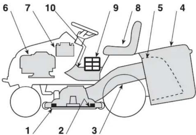
2.2 IDENTIFICATION OF MAIN COMPONENTS
The machine is composed of a series of main components that have the following functions:
1.Cutting-meansassembly: this is the casing that houses the rotating cutting means.
2. Cutting means: these are what cut the grass; the fins at the ends help convey the cut grass towards the discharge chute.
3.Dischargechute: this is the part connecting the cutting-means assembly to the grass catcher.
4.Grasscatcher: as well as collecting the grass cuttings, this is also a safety element that stops any objects drawn up by the cutting means from being hurled away from the machine.
5. Rear discharge guard (available upon request): this can be fitted in place of the grass catcher and prevents objects from being drawn up by the cutting means and hurled away from the machine.
6. Engine: this moves the cutting means and the wheels drive.
7. Battery: provides the energy for starting the engine. Its specifications and regulations for use are described in a specific manual.
8. Driver seat: this is where the machine operator sits. It has a sensor connected to safety devices for detecting the presence of the operator.
9. Regulation and safety labels: give reminders on the main regulations for working safely, each of which is explained in chapter 1.
10.Inspectionhatch:for access to make several adjustments.
3. UNPACKING AND ASSEMBLY
For storage and transport purposes, some components of the machine are not installed in the factory and have to be assembled after unpacking. Follow the instructions below.
WARNING! Unpacking and completing the assembly should be done on a flat and stable surface, with enough space for moving the machine and its packaging, always making use of suitable equipment. Do not use the machine until all the indications provided in the "ASSEMBLY" section have been carried out.
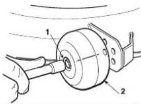
3.1 ACTIVATING AND CONNECTING THE BATTERY
IMPORTANT DRY CHARGE BATTERY!
The battery (1) is housed behind the engine and secured with a strap (2).
Unfasten the strap (2) and remove the battery. Remove the sealing tape and pour in the electrolytic solution (3) (diluted sulphuric acid not supplied: specific weight 1.280, distributing it evenly among the six elements until it reaches the "UPPER LEVEL" marking on the battery.
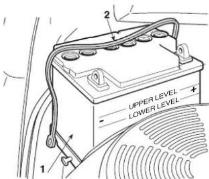
IMPORTANT The electrolyte solution must not exceed 30^ / 86^ during the filling process.
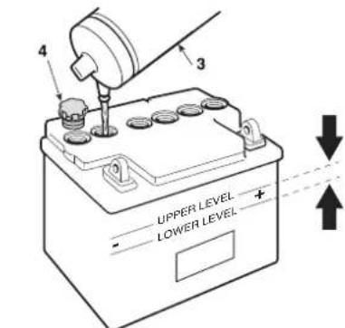
Leave the battery standing for at least half an hour after filling. The electrolyte solution level should drop. Pour the electrolyte solution again up to the "UPPER LEVEL" reference mark.
It is important for the level to stay always between the "UPPER LEVEL" and "LOWER LEVEL" reference marks on the battery.
Place and tighten the six caps (4) provided and charge the battery.
IMPORTANT After
activating the battery, always charge the battery completely with the help of your dealer, who will have all the right equipment. The battery charger is NOT able to charge the battery for the first time after activation.
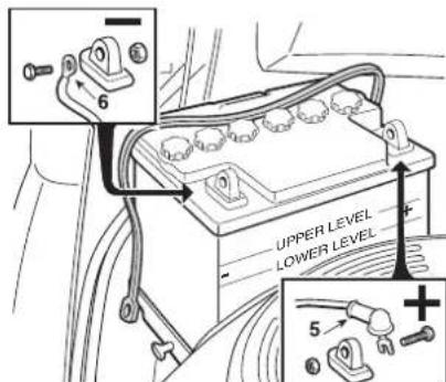
First connect the red wire (5) to the positive pole (+) and then the black wire (6) to the negative pole (-) , using the screws supplied as shown. Apply silicone grease to the terminals and check that the protective cap for the red wire (5) is in place.
IMPORTANT To prevent the safety device in the electronic circuit board from cutting in, never start the engine until the battery is fully charged!
WARNING! Battery acid is corrosive and polluting. Wear protective gloves when handling the battery and dispose of the battery in accordance with the regulations in force.
IMPORTANT Use ONLY the specific battery mod. CNB 31500-VK1-810-M1.
3.2 ASSEMBLING THE GRASS CATCHER
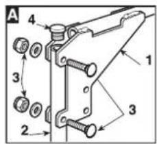
A) Join the upper part of the frame (1) to the front component (2)
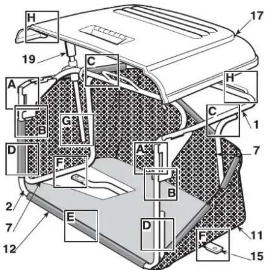
using the supplied screws and nuts (3) as shown. Fit the two rubber caps (4) into the holes in the tube of front frame (2).
HF2…HT
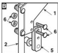
B) Before fully tightening the nuts (3), insert the two supports (5) between the upper chassis plates (1), with the rollers facing inwards, and secure them with screws and nuts (6); then tighten the nuts (3).
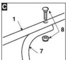
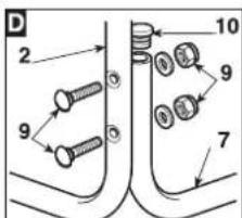
C-D) Mount the two side elements (7), using screws and nuts (8 and 9) as shown. Fit the two rubber caps (10) into the holes of the two side elements (7)
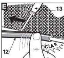
E) Insert the assembled frame in the canvas cover (11) making sure it is correctly positioned on the base perimeter. Hook the plastic profiles (12) onto the frame tubes with the aid of a screw-driver (13).

HF2…HB
HF2…HM
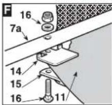
F) Place the plate (14) between the canvas and the lower part of the chassis right element (7a) and line up the holes.
F) Attach the stiffening bar (15) under the frame using the screws and nuts (16) and keeping the flat part turned towards the canvas.
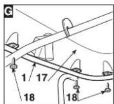
G) Mount the cover (17) and fasten it to the upper part of the frame (1) with the six screws (18).

HF2…HB
HF2…HM·
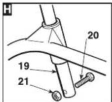
H) Insert the emptying lever (19) in its position and put in the limit stop screw (20) with its nut (21).
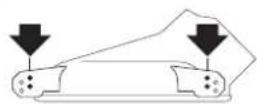
3.3 ASSEMBLING THE GRASS CATCHER BRACKETS
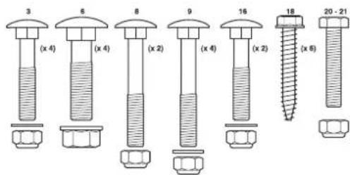
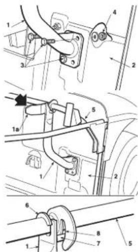
Fit the two brackets (1) on the rear plate (2), using for each bracket three screws (3) which are supplied, as shown, without fully tightening the nuts (4).
The brackets (1) must be mounted in a way that the fins (1a) point inwards.
Fasten to the supports the upper part (5) of the grass catcher frame e and centre it up with the rear plate (2).
Adjust the position of both brackets (1) in relation to the slot (6) so that, by turning the grass catcher frame, the pin (7) slots in place (8).
Make sure again that the frame (5) is well centered in relation to the rear plate (2) and that the rotation movement takes place regularly, as indicated
above, then tighten the screws fully (3) and the fastening (4) nuts.
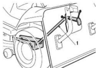
3.4 ASSEMBLING THE LEVERS FOR TIPPING THE GRASS CATCHER

HF2…HT
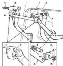
Fit the lever shaft (1) in the groove between the two plates (2) and fasten them to the inner grass catcher brackets (3) using the nuts and screws supplied (4), as shown by the sequence in the figure.
Connect the end of the rod (5) of the lifting piston to the lever (6) with the pin (7) and attach the two snap rings (8).
Before attaching the grass catcher to its supports, make sure that the tipping lever moves properly.
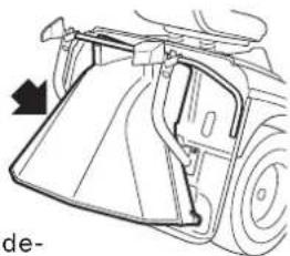
3.5 REMOVAL OF THE GRASS CATCHER PAWL SPRING RETAINER
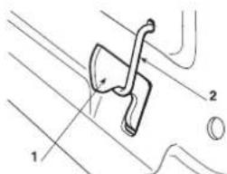
For transport reasons the grass catcher (1) pawl spring is fastened to the rear plate by the retainer (2). This retainer must be removed before the grass catcher frames are fitted and must not be used any longer.
3.6 FITTING THE FRONT BUMPER
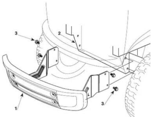
Mount the front bumper (1) on the bottom of the frame (2) using the four screws (3).
4. CONTROLS AND INSTRUMENTS
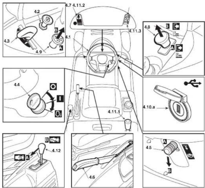
4.1 STEERING WHEEL
Turns the front wheels.
4.2 CHOKE CONTROL
Used to turn on the engine when cold. It enriches the mixture and must only be used for the necessary time.
4.3 THROTTLE LEVER
Adjusts the engine speed. The positions are indicated on the plate showing the following symbols:

“SLOW” for minimum engine speed

"FAST" for maximum engine speed
- When moving from one area to another, put the lever in a position between «SLOW» and «FAST».
- When cutting, shift into "FAST".
4.4 KEY IGNITION SWITCH
This key operated control has three positions:

OFF> everything is switched off;

"ON" activates all parts;

START Switch on the starter motor to ignite the engine.
On being released at the «START» position, the key will automatically return to «ON».
This lever stops the machine from moving when it has been parked. There are two positions:
_A = Brake disengaged
P B = Brake engaged
- The brake is engaged by pressing the pedal (4.21) right down and moving the lever to position «B». When you take your foot off the pedal it will be blocked by the lever in the down position.
- The "Brake engaged" condition is shown by the lighting of a pilot lamp (4.13.e).
- To disengage the parking brake, press the pedal (4.21). The lever will return to position «A».
Use this lever to raise and lower the cutting-means assembly to one of the 7 different cutting heights.
1
7
中
- To go from one height to another, press the release button at the end of the lever.

By pressing and holding this button, it is possible to switch to reverse gear with the cutting means engaged without causing the engine to stop.
4.8 CUTTING MEANS ENGAGE AND BRAKE CONTROLS
This mushroom-head button allows you to engage the cutting means using the electromagnetic clutch:

Pressed
=Cuttingmeans disengaged

L «B»Pulled=
Cutting means engaged
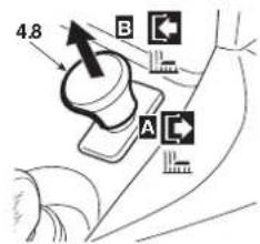
The status "Cutting means engaged" is indicated when the indicator light comes on (4.13.g).
- If you engage the cutting means without taking the necessary safety precautions, the engine shuts down and cannot be restarted (5.2).
- In disengaging the cutting mean (Pos. «A»), a brake is simultaneously activated which stops their rotation within a few seconds.
- Switching the cutting means into reverse gear is only possible by pressing and holding button 4.7.
4.9CRUISECONTROL
HF2417HM
HF2417HT
HF2625H
.
This device keeps the machine at the desired drive speed without having to press the pedal (4.22).
The mushroom-head button has two positions:

- A = Pressed.Devicedisengaged (off)
- B = Pulled. Device engaged (on)
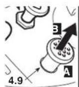
If you turn on the device while driving, the machine maintains the speed reached at that time without having to press the pedal (4.22).
The device cannot be used when driving in reverse.
- while the device is on, it is not possible to operate the reverse pedal (fig. 4.23).
- On uphill or downhill stretches, the speed may vary from that set on level ground.
To turn off the device and reset pedal speed control (4.22) just
or
- press the brake pedal (4.21).
In both cases the mushroom-head button automatically returns to position «Pressed».
4.10.a AUXILIARY SOCKET FOR USB ACCESSORIES
HF2417HM
HF2417HT
HF2625H
This socket can charge USB devices. It is only used for recharging. The socket has no communication function with the connected USB device.
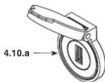
The socket is only live when the key (4.4) is in the «ON» position.
Recharge the USB device with the engine running to avoid draining the battery.
Do not charge the USB accessory in wet or rainy conditions. If used in these conditions, the warranty will be invalidated and the manufacturer will not be held liable for any problems.
Do not open the USB plug in the rain or in dusty areas.
Do not use any equipment while moving or cutting.
Before connecting the equipment to the auxiliary socket, make sure all necessary data have been saved. If data is deleted while using the USB port, the manufacturer accepts no liability.
4.10.b USB ACCESSORY HOLDER
HF2417HM· HF2417HT· HF2625H
Support to hold the USB accessory
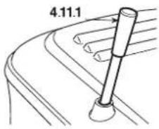
4.11 GRASS CATCHER TIPPING CONTROL
HF2…HB· HF2…HM·
The grass catcher may be tipped to empty by pulling the lever (4.11.1), which can be extracted from its housing.
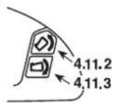
HF2…HT
To empty the grass catcher, press the button (4.11.2) and hold it down until the bag reaches its highest position. (5.4.6).
The grass catcher returns to the working position by pressing the button (4.11.3), keeping it pressed until the pawl hooks into place and the control motor stops.
4.12 "MULCHING" ENGAGE LEVER
HF2417HM· HF2417HT· HF2625H
"Mulching" is engaged with the lever.
A = function engaged
B = function disengaged
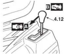
- Only move the gear shift when the cutting means is disengaged.
- With the "mulching" function engaged, the exit guards must always be fitted (grass catcher or discharge guard) (5.3.5).
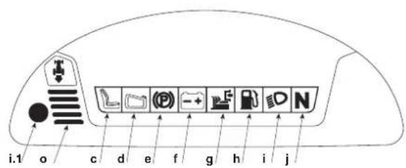
4.13 INDICATOR LIGHTS AND AUDIBLE WARNING DEVICE ON THE CONTROL PANEL
HF2317
HF2417HB/HM· HF2625HM

HF2417HT· HF2625HT·

When the key (4.4) is turned in the «ON» position, all the lamps light on at the same time for about one second (with a brief sound warning) to indicate that the machine is working properly.
The display (a) enters into "information" mode and by using the MODE (b) button it is possible to select the following functions:
- a.1) Hour counter: Alphanumeric digits show the hours driven, divided into hours and tenths of hours. The unit of measurement is followed by the letter h;
HF2625…
- a.2) RPM counter: indicates the engine rotational speed by numerical values.
Displayed value:
< 1600 min-1 engine at minimum speed
2600 min-1 travelling speed, cutting speed
- a.3) Voltmeter: The alphanumeric digits show the battery voltage.
Briefly press the MODE button and release it to turn the icons a.1, a.2, a.3 on in sequence. The alphanumeric digits on the display show the data associated with the selected icon, the last digit is reserved for the unit of measurement.
Do not use RPM counter value to set engine speed.
Afterwards, when a lamp comes on, it indicates:
c) the operator is absent;
d) grass catcher missing;
If it flashes, it means that the grass catcher is full and needs to be emptied.
e) parking brake engaged;
f) Battery not fully recharged: Seek out the causes in chapter 7 of this manual;
If it is blinking, it means that the battery is reaching the over-voltage threshold; stop the machine immediately, disconnect the battery and contact an authorised service centre.
g) cutting means engaged;
h) fuel in reserve: indicates that there are about 1.5 litres left in the tank, sufficient for about 30-40 minutes of normal work.
i) D headlights on;
- i.1) The sensor inside the control panel controls the automatic switching on of the headlights after a few seconds of darkness and their switching off after a few seconds of brightness. To avoid unwanted switching on, keep the sensor area clean and do not place any rags or objects on the control panel.
The brightness level of the headlights may drop for a few seconds due to a power-loss during start-up.
WARNING!
Do not look directly at the LED headlight. ly affect the eyes.
j) N transmissionin"neutral".
k) engine lubrication anomalies: stop the engine immediately, check the oil level (5.3.3) and contact your dealer if the problem persists.
I) The inclination of the machine has reached a non-recommended gradient
NOTE This icon is only informative and helps the user to know the angle of inclination of the machine. The light may light up in the event of abrupt start/stop or sudden steering. Avoid these types of actions.
NOTE Assemble all components correctly following the assembly instructions described in the manual otherwise the tilt indicator may not work properly.
The light timing of the icon can be influenced by the weight of the operator, the weight of the grass catcher and the tyre pressure.
It is possible to change the light timing when an optional accessory is mounted.
The calibration of the sensor used for the light function must be performed by your service provider in order for it to function correctly.
NOTE
If the lamps light up often in wrong situa
tions, please contact your Dealer (for example, the icon lights up with the machine on a flat surface or on a low slope).
m) Maintenance needed.
As soon as the indicator light illuminates, the hourly intervention threshold appears on the display as a code:
M20 = Maintenance in 20 hours
M50 = Maintenance in 50 hours
M100 = Maintenance in 100 hours
M300 = Maintenance in 300 hours
Maintenance work to be performed for each hourly threshold is specified in (6.2).
The maintenance code remains on the display until the engine is turned on or the display functions are changed. The maintenance light instead remains on regardless of the engine status or display functions.
If more than one intervention threshold is reached at the same time, the corresponding maintenance codes alternate on the display every 2 seconds, in ascending order.
After each maintenance, reset the operation, otherwise both the intervention code and the icon will remain on the display and the maintenance interval will not be accurate.
To reset the operation:
Press and hold "MODE" button (4.13.b) for more than 10 seconds, with the key in the «ON» position and the engine off.
The maintenance code and the icon will be displayed again when the next maintenance hourly threshold is reached.
If the maintenance instructions are reset before the hourly intervention threshold is reached, the maintenance schedule is still displayed at the first useful interval. In this case, reset the operation again if the maintenance has already been performed.

HF2417…
If the maintenance instructions cannot be reset immediately after the engine has stopped, wait until the battery voltage drops below 12.7V. Then try to check the maintenance code.

HF2625…
n) Engine RPM indicator: The notches displayed on the graph scale increase as the engine RPM increases. The graphic indicator and the numerical value on the display (a.2) change simultaneously.
o) There are two types of sound warnings:
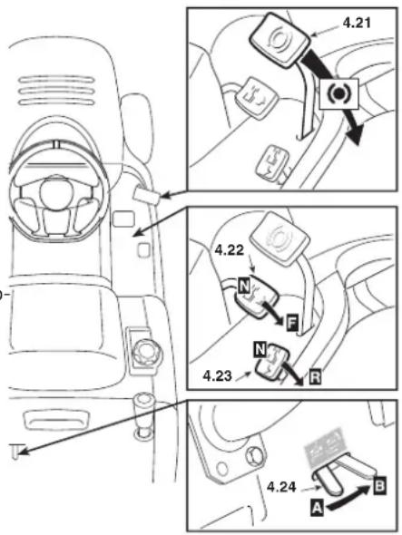
4.21 BRAKE PEDAL
This pedal works the brake on the rear wheels.
4.22 ACCELERATOR PEDAL
This pedal is used to engage the traction to the back wheels in forward drive and adjust the speed of the machine.
-
Increasing the pressure on the pedal progressively increases the speed of the machine.
-
The pedal automatically goes into neutral «N» when released.
-
The "neutral" condition «N» is shown by the lighting of a pilot lamp (4.13.j).
4.23 REVERSE PEDAL
This pedal is used to engage the wheel drive in reverse and adjust the speed of the machine.
-Increasingthe pressure on the pedal progressively increases the speed of the machine.
The pedal automatically goes into neutral N when released.
The "neutral" condition «N» is shown by the lighting of a pilot lamp (4.13.j).
WARNING!
Reverse must be engaged when the machine has stopped.
NOTE If one of the traction pedals is operated with the parking brake (4.5) engaged, the engine stops.
4.24 LEVER TO RELEASE THE HYDROSTATIC TRANSMISSION
This lever has two positions as shown on the label:

A = Transmission engaged: for all usage conditions, when moving and during cutting;

B = Transmission disengaged: this makes it much easier to move the machine by hand, with the engine turned off.
5. OPERATING INSTRUCTIONS
5.1 SAFETY RECOMMENDATIONS
DANGER! The machine must only be used for the purpose for which it was designed (cutting and collection of grass).
Using the machine in any other way is considered "improper use" which will invalidate the warranty, relieve the manufacturer from all liabilities, and the user will consequently be liable for all and any damage or injury to himself or others. Examples of improper use may include, but are not limited to:
- transporting people, children or animals on the machine or on a trailer;
- towing or pushing loads without the use of the specified attachment for towing;
- using the machine for riding over unstable, slippery, icy, stony, rough, marshy ground or puddles that do not allow the consistency of the ground to be assessed;
using of the machine for leaf or debris collection; using the cutting means on surfaces other than grass.
DANGER! Do not tamper with or remove the safety devices installed on the machine. REMEMBER THAT THE USER IS ALWAYS RESPONSIBLE FOR DAMAGE AND INJURIES TO OTHERS.
Before using the machine:
- read the general safety regulations (1.1), paying particular attention to driving and cutting on slopes;
- carefully read the instructions for use, become familiar with the controls and on how to quickly stop the cutting means and engine.
- never put your hands or feet next to or beneath the rotating parts and always keep away from the exit.
Do not use the machine when in a precarious state of health or under the effect of medicines or other substances that can reduce your reflex actions and your ability to concentrate.
It is the user's responsibility to assess the potential risk of the area where work is to be carried out, as well as to take all the necessary steps to ensure his own safety and that of others, particularly on slopes or rough, slippery and unstable ground.
Do not leave the machine stopped on high grass with the engine running to avoid the risk of starting a fire.
WARNING! This machine must not be used on slopes greater than 10^ (17%) (5.5).
IMPORTANT All the references relating to the positions of controls are described in chapter 4.
5.2 WHY THE SAFETY DEVICES CUT IN
The safety devices work in two ways:
- they prevent the engine from starting if all the safety requirements have not been met;
- by stopping the engine if even just one of the safety requirements is lacking.
To start the engine it will be necessary that:
- the transmission is in "neutral";
- all the cutting means are correctly in place;
- the operator is seated.
The engine stops when:
- the operator leaves his seat;
- the grass catcher is lifted or the discharge guard removed without disengaging the cutting means;
- switch to reverse gear with the cutting means engaged. This eventuality can be excluded by pressing and holding button 4.7.
- the forward drive or the reverse is engaged with the parking brake applied.
The table below shows various operating conditions, highlighting why the safety device shuts down the engine.
| OPERATOR | GRASS CATCHER | CUTTING MEANS | TRANSMISSION | BRAKE | ENGINE |
| A) CONTROL PANEL SWITCHED ON (Ignition key in «ON» position) |
| Seated | YES | Disengaged | «N» | Engaged | Stopped |
| Seated | NO | Disengaged | «N» | Disengaged | Stopped |
| B) STARTING (Ignition key on «START» position) |
| Seated | -/- | Disengaged | F/R(▲) | Engaged | DOES NOT start |
| Seated | -/- | Engaged | «N» | Engaged | DOES NOT start |
| None | -/- | Disengaged | «N» | Disengaged | DOES NOT start |
| C) WHILE DRIVING (Ignition key on «ON» position) |
| Seated | YES | Disengaged | E/R(▲) | Engaged | Stops |
| None | YES | Disengaged | «N» | Disengaged | Stops |
| D) WHEN CUTTING (Key in «ON» position) |
| Seated | NO | Engaged | -/- | Disengaged | Stops |
| Seated | YES | Engaged | R | Disengaged | \( Stops^* \) |
| None | YES | Disengaged | «N» | Disengaged | Stops |
| None | YES | Engaged | -/- | Engaged | Stops |
| * This eventuality can be excluded by pressing and holding button 4.7 |
| ** F: Forward gear engaged - R: Reverse gear engaged |
5.3 PRELIMINARY OPERATIONS BEFORE STARTING WORK
Before starting to work, it is necessary to carry out several checks and operations to ensure you can work efficiently and in maximum safety.
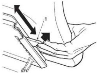
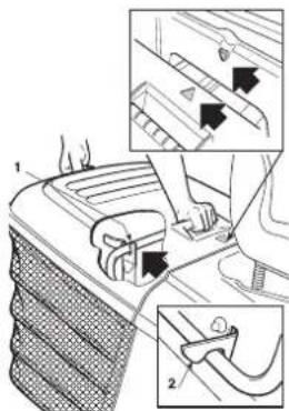
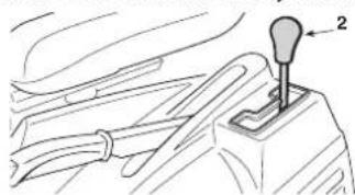
5.3.1 Seat adjustment
The seat is adjustable and slides into six different positions.
Adjustment is made by lifting the handle (1) and sliding the seat until it is locked in the required position.
5.3.2Tyrepressor
Unscrew the valve caps and connect a compressed air line with a gauge to the valves.
Having the right tyre pressure is the main condition for ensuring that the cutting-means assembly is horizontal and mows evenly. The pressures are:
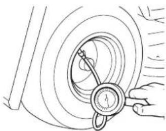
FRONT 1.5 bar (13 x 5.00-6)
1.0 bar (15 x 6.00-6)
REAR 1.2 bar
5.3.3 Filling with oil and fuel
IMPORTANT
Use SAE 10W30 oil and unleaded petrol (green)
Euro 95.
IMPORTANT
Running the engine with insufficient oil can cause
very serious damage. Using non-detergent or two-stroke oil can shorten engine life.
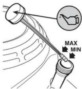
On a flat surface with the engine off, remove the cap with the dipstick and dry it. Push it fully in without screwing it on, then pull it out to check the oil level. If the level is near or below the lower limit (MIN) of the dipstick, top up with recommended oil until the upper limit (MAX) is reached. Screw the cap with the dipstick back on.
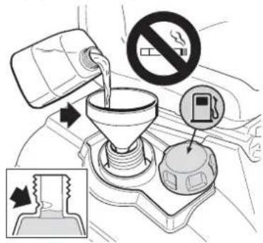
Use a funnel to refuel.
Avoid filling the tank completely; the maximum level is indicated on the neck of the tank.
The tank's capacity is indicated in chapter 10.
IMPORTANT
Damages to the drive system or engine perfor
mance caused by negligent storage operations are not covered by the warranty.
NOTE
If petrol has been spilled on the body, clean up all
traces immediately.
DANGER!
Refuelling should be carried out in an open or area with engine stopped. Always remember es are inflammable. DO NOT TAKE A NAKED E TANK'S OPENING IN ORDER TO SEE THE ENTS AND DO NOT SMOKE WHEN REFUEL
- Petrol containing alcohol
IMPORTANT
If petrol containing alcohol is used, make sure a number is at least equal to the index recommended in the index 86). There are two types of petrol/alcohol containing ethanol and the other containing methanol.
Fuel specifications necessary to maintain the performance of the emission control system: E10 fuel mentioned in EU legislation. Never use gasoline/alcohol mixtures containing more than 10% ethanol. Do not use petrol with a methanol level (methyl alcohol or wood alcohol) higher than 5% and without solvents or methanol corrosion inhibitors.
IMPORTANT
- Damage caused to the fuel system or engine performance problems resulting from the use of petrol containing more than the recommended level of alcohol are not covered by the warranty.
- Before refuelling at a not well known petrol station, find out if the petrol contains alcohol and, if so, what type of alcohol is used and in what percentage.
If unwanted symptoms of operation are detected while using a specific gasoline, go back to a gasoline with an alcohol level definitely lower than the recommended amount.
5.3.4 Checking the braking system
Make sure that the machine's braking capacity is adequate for the conditions of usage. Avoid starting the machine if you have doubts on the brake efficiency. If necessary, adjust the brake 6.3.4) and if you still have doubts on its efficiency, consult your dealer.
5.3.5 Fitting the exit guards (grass catcher or rear discharge guard)
WARNING!
Never use the machine without having fitted
HF2…
The guards must be fitted with the tipping levers lowered.
Hook on the grass catcher inserting the upper frame tube in the holes on the two supports (1).
To centre the grass catcher correctly, align the two symbols on the grass catcher and on the back plate
Make sure that the lower pipe of the grass catcher opening is attached to the pawl (2). If the hook is difficult or too loose, adjust the return spring (6.3.6).
If you decide to work without the grass catcher, a discharge guard kit is available upon request (8.2). This has to be attached to the rear plate as indicated in the instructions.
5.3.6 Checking machine safety and efficiency
-
Check that the safety devices function as described (5.2).
-
Check that the brake is in perfect working order.
- Do not start mowing if the cutting means vibrate or if you are unsure whether they are sharp enough. Always remember that: - A badly sharpened cutting means pulls at the grass and causes the lawn to turn yellow. - A loose cutting means causes abnormal vibrations and can be dangerous.
WARNING! Do not use the machine if you are unsure whether it is working safely or efficiently. If in doubt, contact your Dealer immediately to make the necessary checks or repairs.
5.4 USING THE MACHINE
5.4.1 Starting
DANGER! All starting operations have to be effected in an open or well ventilated area. ALWAYS REMEMBER THAT EXHAUST GASES ARE TOXIC!
To start the engine
put the transmission into neutral (N) 4.22
disengage the cutting means (4.8);
- apply the parking brake on sloping ground;
- If cold starting: engage the Choke (4.2);
- if the engine is already warm, just put the lever between «SLOW» and «FAST»;
- insert the ignition key and turn to «ON» to make electrical contact, then turn to «START» to start the engine;
- release the ignition key once the engine has started.
When the engine has started, put the throttle in the «SLOW» position.
IMPORTANT The choke must be closed as soon as the engine is running smoothly. Using it when the engine is already warm can foul the spark plugs and cause the engine to run erratically.
NOTE If there are engine starting problems, do not insist as you can risk running the battery flat and flooding the engine. Turn the key to the «OFF» position, wait for a few seconds and then repeat the operation. If the malfunction persists, refer to the engine manual and chapter «7» in this manual.
IMPORTANT Always bear in mind that the safety devices prevent the engine from starting if safety requirements have not been met (5.2). In these cases, once the situation has been corrected, the key must first be turned back to "OFF" before the engine can be restarted.
5.4.2 Forward drive without mowing
WARNING! This machine has not been approved for use on public roads. It must be used (as indicated by the highway code) in private areas closed to traffic.
When moving the machine:
disengage the cutting means;
- bring the cutting-means assembly to the highest position (position «7»).
Put the throttle lever between the «SLOW» and «FAST» positions. Disengage the parking brake and release the brake pedal (4.21). Press the drive pedal (4.22) forward and reach the required speed by gradually increasing pressure on the pedal and acting the throttle.
WARNING! Drive must be engaged as described (22) to prevent sudden engagement from causing tipping up and loss of control of the vehicle, particularly on slopes.
5.4.3 Braking
First reduce the machine's speed by reducing the engine's r.p.m., and then press the brake pedal (4.21) to slow down the machine until it stops.
NOTE The machine already slows down considerably by just releasing the drive pedal forward or reverse.
5.4.4 Reverse
Reverse MUST be engaged only when the machine has stopped.
When the machine is stopped, start the reverse movement by pressing the drive pedal in the «R» direction (4.23).
5.4.5 Grass cutting
On reaching the area to be mowed, check that the grass catcher or the discharge guard are correctly fitted in place.
HF24...HF26...
The function of the anti-chipping wheels is to maintain a space between the ground and the edge of the cutting means assembly to prevent the latter from damaging the turf on uneven surfaces. Each anti-chipping wheel on the cutting-means assembly can be fitted at two different heights: in the lowest position it serves to maintenance the space; its efficacy is excluded when in the highest position.
To change position unscrew and extract the pin (1) and reposition the wheel (2) in the hole higher or lower of the row indicated in the illustration.
WARNING! This should always be performed on all four wheels, WITH THE ENGINE OFF AND CUTTING MEANS DISENGAGED.
To start cutting:
- move the throttle to «FAST»;
- bring the cutting-means assembly to the highest position;
- engage the cutting means (4.8);
- start moving forwards on the grass very slowly and with utmost caution, as already described;
- adjust the forward speed and the cutting height (4.6) according to the lawn condition (height, density and dampness of the grass). On flat ground, these general conditions can be followed:
High and dense grass - wet lawn 2.5 km/h
Average condition grass 4 ... 6 km/h
Low grass - dry lawn over 6 km/h
The speed is controlled in a gradual and progressive way by the pressure on the drive pedal.
WARNING!
When cutting on sloping ground, the forward
speed must be reduced to ensure safe conditions (1.2 - 5.5).
Whatever the conditions, always reduce the speed if you notice a drop in engine speed – if you travel too fast compared to the amount of grass being cut, you will not be able to mow the grass well.
Disengage the cutting means and raise the cutting-means assembly as high as possible whenever you need to get past an obstacle.
5.4.6 Emptying the grass catcher
Do not let the grass catcher become too full as this may block the discharge chute.
An intermittent acoustic signal and the flashing of the lamp (4.13.d) indicate that the grass catcher is full; at this point:
- lower the engine speed;
- shift into neutral (N) (4.22 or 4.23) and stop forward movement;
- engage the parking brake on slopes;
disengage the cutting means (4.8) and the warning sound will stop;
HF2…HB
HF2…HM
NOTE
The emptying of the grass catcher can only be
done with the cutting means disengaged, otherwise the engine stops.
Pull out the lever (1) 4.11.1) and tip up the grass catcher to empty it;
- close up the grass catcher so that it hooks onto the pawl (2) and put the lever (1) back into place.
HF2…HT
NOTE
The grass
catcher tipping control only operates with the cutting means disengaged
with the operator seated, keep the button (3) 4.11.2 pressed until the grass catcher is completely tipped over;
once emptied, keep the button (4) 4.11.3 pressed until the grass catcher has lowered completely while checking that the pawl (2) stays hooked on.
NOTE
At times the audible warning may be heard at the
moment of engaging the cutting means even when the grass catcher has been emptied. This is due to grass-cuttings left on the sensor (1) of the micro-switch. To stop the signal disengage the cutting means and then immediately engage it again. If the audible warning signal persists, stop the engine, remove the grass catcher and free the sensor of any remaining grass-cuttings (1).
5.4.7 Unblocking the discharge chute
Cutting very tall or wet grass, particularly at excessively high speed, can clog up the discharge chute. If this happens proceed as follows:

- stop forward movement immediately, disengage the cutting means and stop the engine;
- remove the grass catcher or the discharge guard;
- remove the grass cuttings; you can reach them from the discharge chute opening.
WARNING!
This job must only be performed with the en
gine turned off.
5.4.8 “Mulching”
"Mulching" implies recycling grass inside the cutting-means assembly and at the same time finely chopping the mown grass and leaving it on the lawn.
If the mown grass is scattered around the cutting-means assembly or left in heaps during the mulching operation, the grass may be too long or cut too short. The mulching cutting height must be set to about 1/3 of the grass height (maximum 10-13 cm before mulching).

HF2317…
HF2417HB
This accessory (available upon request) must be mounted as shown in the relative instructions.

HF2417HM
HF2417HT
HF2625H
The machine is equipped with a mechanism to switch between grass collection and mulching functions. Have a good understanding of these two functions' operating conditions before using them
"Mulching" is engaged or disengaged via a mulching engage lever (2) (4.12).
Operate the mulching engage lever with the grass catcher removed from the machine, to make sure it works freely and it is
not obstructed by grass that could affect its operation. Use a stick or similar tool to remove any grass from in front of the hatch.
IMPORTANT
Over-stressing the lever with the cable noted or with grass deposits can cause the cable to support to be deformed due to overloading. If the patched, do not force, but contact your Dealer.
After mowing
Once the cutting session is over, it is recommended to clean the cutting-means assembly, the discharge chute and the grass catcher to avoid any inconveniences and ensure trouble-free functioning the next time the machine is used.
Stop the engine, remove the key, apply the parking brake and remove the grass catcher.
Visually inspect the discharge chute to check that the discharge chute is not clogged with grass (remove any grass cuttings clogging the discharge chute).
5.4.9 End of mowing
When you have finished mowing, disengage the cutting means, reduce the engine speed and ride the machine with the cutting-means assembly in the highest position.
5.4.10 End of work
Stop the machine, put the throttle lever in the «SLOW» position and turn off the engine by putting the ignition key into the «OFF» position. This operation causes the fuel valve to close automatically.
WARNING! Always take out the ignition key before leaving the machine unattended!
5.4.11 Cleaning and storage
Put the machine away in a dry place protected from the weather and, if possible, cover it with a cloth. After each mowing session, clean the outside of the machine, empty the grass catcher and shake it to remove residual grass and earth.
Look for and eliminate all the grass that has accumulated inside the engine compartment and above the cutting-means assembly, to keep the machine at an optimal level of efficiency.
WARNING! Always empty the grass catcher and do not leave containers full of cut grass inside storage areas.
Clean the plastic parts of the body with a damp sponge using water and detergent, taking care not to wet the engine, the electrical parts or the control panel located under the control panel.
IMPORTANT Never use hose nozzles or harsh detergents for cleaning the body and engine!
When washing the inside of the cutting-means assembly and the discharge chute, the machine must be on firm ground with:
- the grass catcher or the discharge guard fitted in place;
the operator seated;
the engine running;
the transmission in neutral;
- the parking brake engaged;
the cutting means engaged.
Connect a water hose to each of the pipe fittings (1) one at a time and run water through each one for a few minutes, with the cutting means moving.
When washing, the cutting-means assembly should be lowest position down. Now remove the grass catcher, empty and rinse it, then place it where it can dry quickly.
IMPORTANT In order not to compromise the efficiency of the electromagnetic clutch: -do not let the clutch come
into contact with oil;
- do not spray pressurised water directly on the clutch unit;
- do not clean the clutch with petrol.
5.4.12 Disassembling the belt guard and cleaning the cutting-means assembly
WARNING! Do not let debris and dried grass accumulate in the upper part of the cutting-means assembly in order to maintain maximum machine efficiency and safety levels. This operation should be performed 2-3 times a year and before storing the machine away for a period of time (by way of example only, at the end of the season).
WARNING! Your machine is fitted with two transmission chain guards (one on the right and one on the left) to prevent accidental contact during use.
HF2317
The left guard (1a) is fixed by:
two nuts (2a), unscrew using a 10mm key;
- a front screw (3a) and a central screw (3b), unscrew using a Torx T30 key;
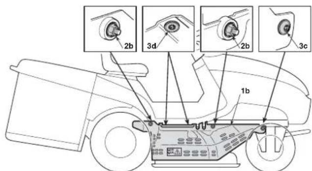
The right guard (1b) is fixed by:
-two nuts (2b), unscrew using a 10mm key;
- a front screw (3c) and a central screw (3d), unscrew using a Torx T30 key.
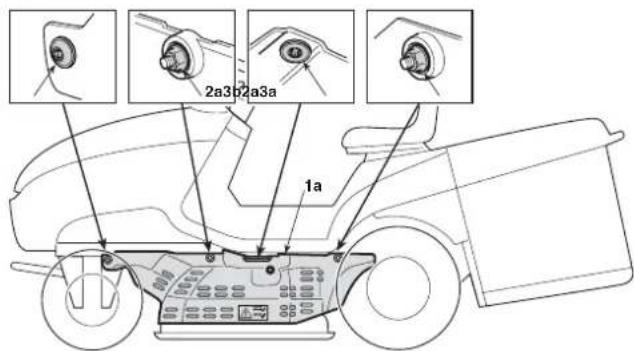
NOTE When removing the left guard (1a) make sure you do not disconnect the hose from the fitting used to clean the inside of the cutting-means assembly.
When remounting the left and right guards, replace all the nuts (2a) and (2b) and then all the screws.
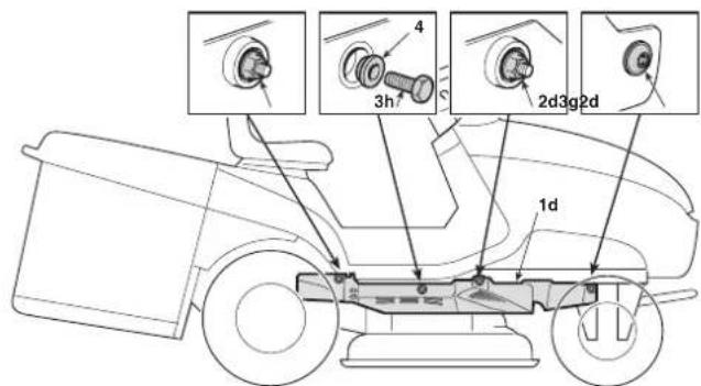
HF24\*HF26\*
The left guard (1c) is fixed by:
- two nuts (2c) unscrew using a 10mm key;
- a front screw (3e), unscrew using a Torx T30 key;
- a central screw (3f) with a spacer (4), unscrew using an 10 mm key;
The right guard (1d) is fixed by:
two nuts (2d) unscrew using a 10mm key;
- a front screw (3g), unscrew using a Torx T30 key.
- a central screw (3h) with a spacer (4), unscrew using an 10 mm key;
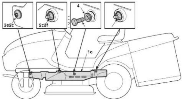
When remounting the left and right guards, make sure the spacers (4) are fitted correctly below the screws (3f) and (3h).
To disassemble each guard and clean the cutting-means assembly: bring the cutting-means assembly to position «1» (completely low position);
- use suitable keys to unscrew the nuts and all the screws, on the left and right, and remove the left and right guards;
- use a jet of compressed air to remove any debris and dirt from the upper section of the cutting-means assembly.
WARNING! The machine must not be used if both guards are not correctly installed. Always replace any damaged guards.
5.4.13 Storage and inactivity for long periods
If the machine is likely to be unused for a long period of time (more than 1 month), disconnect the battery ground cable (black). In addition, lubricate all joints as shown (6.2.1).
WARNING! Carefully remove any dry grass cuttings which may have collected around the engine or silencer to prevent their catching fire the next time the machine is used!
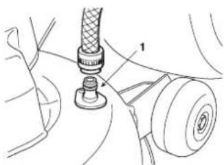
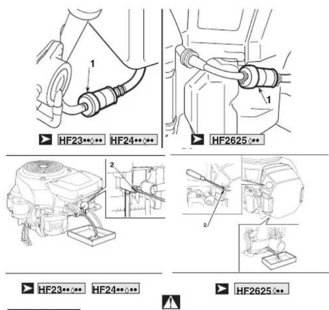
Empty the fuel tank by disconnecting the tube situated at the inlet of the fuel filter (1).
Reconnect the fuel tube.
Loosen the carburetor drain screw (2) and drain the fuel into a suitable container. Tighten the drain screw.
Remove the two spark plugs and pour a tablespoon of clean engine oil into the cylinders. Run the engine for 1 to 2 seconds using the starter motor, by turning the ignition key. This will distribute the oil
evenly in the cylinders. Refit the spark plugs (6.4.5).
DANGER! Petrol is highly flammable. Store the fuel in special containers. Always put the tank and fuel container caps back on and tighten well.
IMPORTANT The battery must be kept in a cool and dry place. Before a long storage period (more than 1 month), always charge the battery using the specific battery charger supplied with the machine and then recharge before using again (6.2.3).
The next time the machine is used, check that there are no fuel leaks from the tubes or carburettor.
5.4.14 Control panel protection device
The electronic circuit board has a self-resetting protector which breaks the circuit if there is a fault in the electrical system. This will stop the engine and is signalled by an acoustic sound alert that is deactivated only by removing the key.
The circuit automatically resets after a few seconds but the cause of the fault should be ascertained and dealt with to avoid reactivating the protection device.
IMPORTANT To avoid activating the protection device:
- do not invert the leads on the battery terminals;
- do not use the machine without its battery or damage may be caused to the charge regulator;
- be careful not to cause short-circuits.
5.5 USING ON SLOPES
Only mow on slopes with gradients up to the maximum already mentioned (max 10^ - 17% ). Lawns on a slope have to be mowed moving up and down and never across them. When changing direction, take great care that the wheels facing up the slope do not hit any obstacles (such as stones, branches, roots, etc.) that may cause the machine to slide sideways, tip over or make you lose control.
The icon (4.13.l) shows that the inclination angle of the machine approach the recommended slope limit.

DANGER! REDUCE SPEED BEFORE ANY CHANGE OF DIRECTION ON SLOPES, and always apply the parking brake before leaving the machine at a standstill and unattended.
WARNING! Take care when beginning forward movement on sloping ground to prevent the risk of tipping up. Reduce the forward speed before going on a slope, particularly downhill.
DANGER! Never switch to reverse gear to decrease speed when going downhill: this could cause loss of control of the machine, especially on slippery ground.
Go down slopes with your foot off the drive pedal 4.22) to use the braking effect of the hydrostatic transmission when the transmission is not engaged.
5.6 TRANSPORT POSITION
WARNING: The machine must be transported on a truck or trailer, use ramps with suitable resistance, width and length. Load the machine with the engine switched off, without a driver and pushed by an adequate number of people. During transport, lower the cutting-means assembly, engage the parking brake and fasten the machine securely to the hauling device with ropes or chains.
5.7 ADVICE ON HOW TO OBTAIN A GOOD CUT
- To keep a lawn green and soft with a good appearance, it should be cut regularly without damaging the grass.
- It is always better to cut the grass when dry.
- The cutting means must be in good condition and well sharpened so that the grass is cut straight without a ragged edge that leads to yellowing at the ends.
- The engine must run at full speed, both to ensure a sharp cut of the grass and to get the necessary thrust to push the cuttings through the discharge chute.
- The frequency of mowing should be in relation to the rate of growth of the grass, which should not be left to grow too much between one cut and the next.
- During hot and dry periods, the grass should be cut a little higher to prevent the ground from drying out.
- If the grass is very tall, it should be cut twice in a twenty-four hour period. The first time with the cutting means at maximum cutting height, possibly reducing the cutting width and the second cut at the height desired.
- The appearance of the lawn will improve if you alternate the cutting in
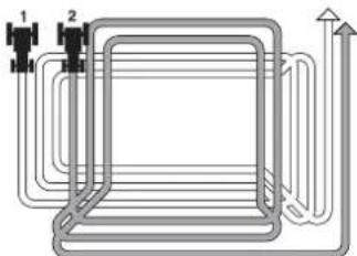
both directions.
- If the discharge chute tends to get blocked with grass, you should reduce the forward speed as it may be too high for the condition of the grass. If the problem persists, the probable causes are either badly sharpened cutting means or deformed fins.
- Be very careful when mowing near bushes or kerbs as these could distort the horizontal position of the cutting-means assembly and damage its edge as well as the cutting means.
5.8 SUMMARY OF MAIN STEPS TO FOLLOW WHEN USING THE MACHINE
| To...You will need to ... |
| Start the engine (5.4.1) | Ensure that all the conditions allowing starting are met, and then turn the key. |
| Go forward (5.4.2) | Apply the throttle;Press the drive pedal in forward gear (4.22). |
| Brake or stop (5.4.3) | Reduce the engine speed and press the brake pedal. |
| Reverse (5.4.4) | Stop the machine;Press the reverse pedal (4.23). |
| Cut the grass (5.4.5) | Fasten the grass catcher or the rear discharge guard;Adjust the height of the anti-chipping wheels (excluded:HF2317**);Adjust the throttle;Engage the cutting means;Adjust the cutting height;Press the drive pedal in forward drive (4.22); |
| Empty the grass catcher (5.4.6) | Stop moving forwards, disengage the cutting means and use the tipping controls to tip up the grass catcher. |
| Unblock the discharge chute (5.4.7) | Operate the cutting height adjusting lever several times to shake and free the discharge chute.Stop moving forwards, disengage the cutting means and turn off the engine.Remove the grass catcher and clean the chute. |
| Engage "Mulching" (5.4.8) | HF2317** HF2417HB* This accessory (available upon request) must be mounted as shown in the relative instructions.HF2417HM* HF2417HT* HF2625** "Mulching" is engaged or disengaged via an appropriate lever (4.12). |
| Finish mowing (5.4.9) | Disengage the cutting means and reduce the engine speed. |
| Stop the engine (5.4.10) | Reduce the engine speed, wait a few seconds, turn the key. |
| Store the machine (5.4.11) | Engage the parking brake, remove the key and, if necessary, wash the machine, the inside of the cutting-means assembly, the discharge chute and the grass catcher. |
6. MAINTENANCE
6.1 SAFETY RECOMMENDATIONS
WARNING!
Before cleaning, maintenance or repair work,
take out the ignition key and read the relevant instructions. Wear suitable clothing and protective gloves when dismantling and refitting the cutting means and in all other hazardous situations for hands. Make sure the engine is cold before starting any maintenance work.
WARNING!
Never use the machine with worn or damaged
parts. Faulty or worn-out parts must always be replaced and never repaired. Only use genuine spare parts: those that are not of an equivalent quality may damage the machine or endanger the safety of yourself and others.
IMPORTANT
Never get rid of used oil, fuel or other pollutants in
unauthorised places!
Summary of the main situations where work may be required
| Whenever ...You will need to ... |
| The cutting means vibrate | Check the fasteners ( -6.3.1) or rebalance the cutting means ( -6.3.1) |
| The cutting means pulls out the grass and causes the lawn to turn yellow | Sharpen the cutting means ( -6.3.1) |
| The cut is uneven Aligning the cutting | -means assembly ( -6.3.2) |
| The cutting means engage unevenly | Regulate the cutting means engagement adjuster ( -6.3.3). |
| The machine does not brake Adjust | the stretcher spring ( -6.3.4) |
| Forward movement is erratic Adjust | the stretcher spring ( -6.3.5) |
| The grass catcher moves around and tends to open | Adjust the spring ( -6.3.6) |
6.2 ROUTINE MAINTENANCE
6.2.1 GUIDE TO SCHEDULEDMAINENCE
This table is to help you maintain your machine's safety and performance. It shows the main maintenance and lubrication operations and their frequency.
HF2417… HF2625…
Always restore the icon and the servicing threshold code
(4.13.m) after performing each maintenance work.
| OPERATION | INTERVAL |
| Perform maintenance at each operating hour or month interval, depending on which occurs first | ACTION | 1 YEARor100HOURS | 20 HOURS | 50 HOURS | 300HOURS |
| Engine oil Check ● | | | | | |
| Change (1) | | | | |
| Air filter Check ● | | | | | |
| Check | | | | |
| Replacing (3) (4) | | | | |
| Cooling air duct grid Check ● | | | | | |
| Muffler Check ● | | | | | |
| Cooling fan grid Check ● | | | | | |
| Battery | Charge | | | | | (∗) |
| Check electrolyte level | | ● | | | |
| Check electrolyte level and acid density | | | | ● | |
| Tyres and tyre pressure | Check | | | | |
| Cutting-means assembly belt | Check | | | | |
| Transmission belt | Check | | ● | | |
| Brake | Brake condition | Check | | | | |
| Brake and clutch rod tightening | Check | | ● (1) | ● (2) | |
| Brake pedal stroke | Checking and adjusting | | | ● | |
| Parking brake | Check | | | ● | |
| Condition of the cutting means bolts | Inspection | ● | | | |
| Tightening the cutting means bolts | Check | | | ● | ● |
| Condition of the cutting means | Check | | | | |
| Front and rear axle greasing | Greasing | | | ● | |
| Spark plug | Cleaning and check | | | | ● |
| Replacing | | | | |
| Throttle cable | Checking and adjusting | | | ● | |
| Tank, tube and filter | Checking and adjusting | | | | |
| Valve clearance Check, replace if necessary | ● | | | | |
| Engine fins and baffles | Checking and adjusting | | | | |
| Drive pedal bushing | Cleaning | | | ● | |
| Mulching system | Cleaning and check | ● | | | |
| Adjustment (if necessary) | | | | |
(*) If the machine has not been used for more than 1 month.
Clean the air filter more frequently if the machine is used in dusty areas.
(1) Use this interval only for first maintenance.
(2) This interval refers to the second and subsequent maintenance.
(3) GCV530
(4)GXV690H
6.2.2 Rear axle
This is a sealed single unit that does not require maintenance. It is permanently lubricated and its lubricant does not need changing or topping up.
6.2.3 Battery
To ensure long life to the battery it is essential to keep it properly maintained. The machine battery must always be charged:
before using the machine for the first time after purchase(3.1);
before leaving the machine idle for a long period;
before starting up the machine after a prolonged period of inactivity.
The machine comes with a connector (1) for recharging; this is connected to the corresponding connector for the special maintenance battery-charger supplied.
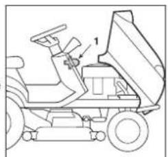
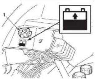
IMPORTANT No device other
than a battery charger should be connected to this connector.
When inactive, the charge level can be kept constant by using the supplied maintenance battery charger.
IMPORTANT The charge must be maintained with the battery charger following the guidelines in the relevant operating instructions. Other recharging systems can irreversibly damage the battery.
A drained battery should be recharged as soon as possible, otherwise the battery elements may be irreparably damaged.
Periodically check the electrolyte level; for topping up, use ONLY distilled battery water.
6.3 CHECKS AND ADJUSTMENTS
6.3.1 Removing, replacing and rebalancing of cutting means
A badly sharpened cutting means pulls out the grass, reduces the loading capacity and causes the lawn to turn yellow.
IMPORTANT To access the cutting means, remove the cuttingmeans assembly using a quick release system that allows easy removal from the machine.
a) Removing the cutting-means assembly
Remove the side guards before removing the cutting-means assembly. (5.4.12).
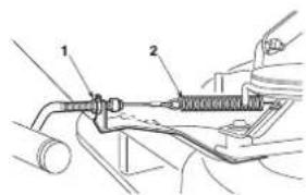
HF2317
After moving the cutting height lever to position «1», pull the engagement cable adjuster out (1) and release the spring (2).
Free the cutting means belt (6) from the clutch pulley (7).
Pull out the two split pins (8) which secure the two connecting rods (9)
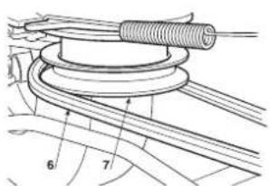
to the frame.
Release the three split pins (10) securing the pins to the lifting lever, being careful to not touch the nuts and locknuts so that, on reassembly it is as parallel as it was before.
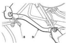
Having checked that there is nothing in the way, the cutting-means assembly can be removed, turning it anti-clockwise so that all the pins come out of their positions.
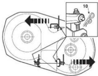
To assemble, perform the operations described above in reverse order making sure that the front end of the discharge chute is posit cutting-means assembly opening.
HF2417HM· HF2417HT· HF2625H
Remove the "Mulching" drive cable. Remove the cotter pin (1) and pull out the eyelet (2). Loosen the nut (3) and remove cable (4).
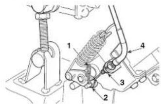
HF24...HF26...
Set the cutting height adjustment lever to position 1
Release the cutting means engagement spring (1).
Loosen the engagement adjuster (2) and remove it from the housing.
Free the cutting means belt (4) from the clutch pulley (5).
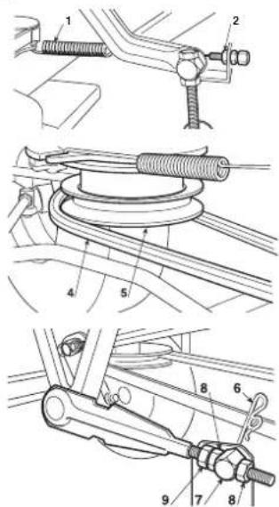
HF24
Remove the two split pins (6) from the two front connecting rod pins (7), without loosening or changing the position of the nuts (8) and locknuts (9).
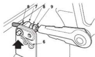
Remove the two split-pins (10) of the rear pins. Then check that there are no obstructions and remove the cutting-means assembly, pulling it out so that all the pins come out of place.
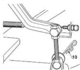
HF26
Remove the two nuts (6) from the two front connecting rod pins (7), without loosening or changing the position of the nuts (8) and locknuts (9).
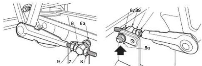
Remove the two split-pins (10) of the rear pins. Then check that there are no obstructions and remove the cutting-means assembly, pulling it out so that all the pins come out of place.
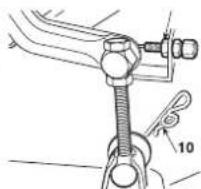
To assemble, make sure the two rear holes on the pin fasteners are used (7); perform the operations described above in reverse order making sure that the front end of the discharge chute is positioned correctly in relation to the cutting-means assembly opening.
b) Removing, replacing and rebalancing of cutting means
WARNING! All operations on the cutting means (dismantling, sharpening, balancing, remounting and/or replacing) require a certain familiarity and special tools. For safety reasons, go to a specialized centre if you do not have the right tools or experience.
WARNING! Always wear strong protective gloves to handle the cutting means.
To remove a cutting means, hold it firmly and undo the central bolt (1a - 1b) using a 15mm key in the direction indicated by the arrow for each cutting means, noting that one of the fixing bolts has a right-hand thread and the other one has a left-hand thread.
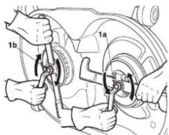
1a = screw with right thread (loosen anti-clockwise)
1b = screw with left thread (tighten clockwise)
The cutting means (2) is attached to the rotor (3) by a bracket (4) and four screws with washers (5).
Use a 10mm key to loosen the four screws (5) and free the cutting means (2) from its bracket (4).
Sharpen the two cutting edges using a medium grade grinding wheel and check the balance by holding the cutting means up with a screwdriver inserted in the central hole.
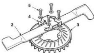
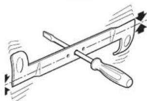
WARNING! Always replace damaged or bent cutting means; never attempt to repair them! ALWAYS USE ORIGINAL CUTTING MEANS!
Only the following pairs of cutting means can be used on this machine:
| HF 2317: 2b | | 80395-Y09-003
(82004345/1) | - | 80394-Y09-003
(82004344/1) | 2a |
| HF 2417: 2b | | 72511-VK1-A11
(82004341/1) | - | 72531-VK1-A11
(82004340/1) | 2a |
| HF 2625: 2b | | 72511-VK1-B11
(82004343/0) | - | 72531-VK1-B11
(82004342/0) | 2a |
WARNING! The cutting means (2) and rotors (3) are different from each other and counter-rotating. During assembly ensure that the original positions are respected.
Reassemble each cutting means (2a - 2b) onto the respective rotor (3a - 3b), following the "RH" (right) and "LH" (left) indications printed on the rotor and inside the cutting-means assembly, then tighten the four screws (5) with the washers using a dynamometric key which is calibrated at 9.5Nm .
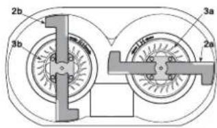
NOTE The "right" and "left" indications refer to the driving position.
WARNING! If one or both shaft hubs (7) come off when dismantling the cutting means, make sure the keys (8) are securely lodged in place. When assembling the cutting means, always follow the instructions given, making sure the cutting means fins are facing towards the inside of the cutting-means assembly and the cupped side of the elastic disc (6) is pressing against the cutting means. Tighten the fixing screws (1a-1b) using a torque wrench set to 45-50 Nm.
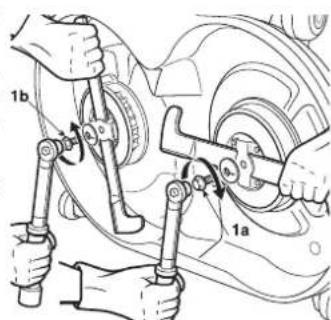
1a = screw with right thread (tighten clockwise)
1b = screw with left thread (tighten anticlockwise)
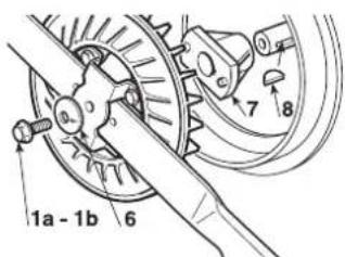
6.3.2 Aligning the cuttingmeans assembly
The cutting-means assembly should be properly adjusted to obtain an evenly mown lawn.
NOTE To achieve good results from cutting, the front part should always be 5 -7 mm lower than the rear.
Put the machine onto a flat surface and check the tyre pressure;
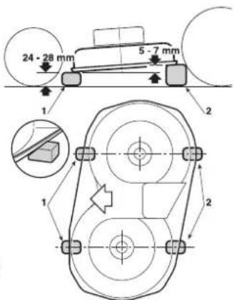
position two 24 - 28mm spacer blocks (1) under the front edge of the cutting-means assembly and two spacer blocks (2) 5 - 7mm higher under the rear edge, making sure they are positioned along the centre line of the cutting means;
- shift the height adjusting lever to position «1».
HF2317…
- Fully loosen the two nuts (3), the nuts (4 - 6 - 8) and the locknuts (5 - 7 - 9) of the three connecting rods until the cuttingmeans assembly is resting on the blocks;
- screw the two upper right nuts (6 - 8) and the lower left nut (4) until the cutting-means assembly starts rising; tighten the three locknuts (5 - 7 - 9) and turn the nuts (3) until a minimal movement of the lifting lever causes analogous movement of all the lifting connecting rods.
Any difference in height from the ground between the left and right sides of the cutting-means assembly can be compensated by turning the two nuts (4 - 8) and locknuts (5 - 9) of just the back connecting rods.
Move the control lever to 2 or 3 different positions, making sure that the cutting-means assembly rises evenly and that the difference in height from the ground remains the same between the front and rear edge.
If the front part tends to rise faster or slower it can be adjusted by turning the nuts (10) on the connecting rod (11).
Screwing the nuts down on the rod will lift the front part and make it rise faster, and unscrewing them will give the opposite effects.
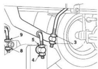
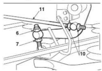
HF24...HF26...
- Loosen the nuts (3), the screws (5) and the locknuts (4-6) on the right and left-hand side, so that the cutting-means assembly is resting firmly on the blocks;
push the two connection rods backwards (7) and tighten the nuts (3) to the respective rods until both the left and right side of the front part of the cutting-means assembly begin to rise and then tighten the locknuts (4);
turn both the rear screws (5) until both the left and right side of the rear part of the cutting-means assembly begin to rise and then tighten the relative locknuts (6);
If you are unable to adjust the cutting-means assembly properly, consult your Dealer.
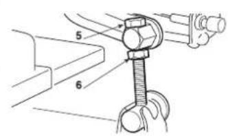
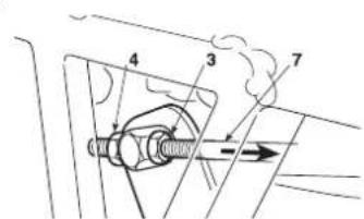
6.3.3 Adjusting the cutting means gear and brake
When you operate the lever to disengage the cutting means, this
also brings the brake into operation which stops rotation within a few seconds.
A stretched cable and/or changes in the length of the belt can impair the correct engagement or rotation of the cutting means.
In such cases, turn the adjuster as foreseen for the model in question.
Adjust the register (1) till the spring (2) is the correct length.
HF2317…
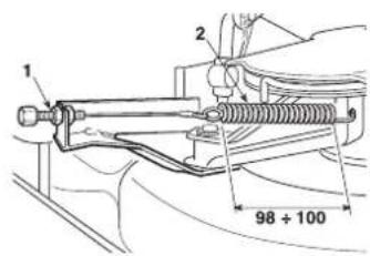
HF2417
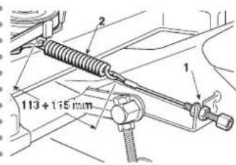
HF2625
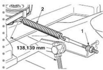
In any case, please contact your Dealer if, after the adjustment, the gear is not able to engage the belt correctly or block the cutting means within a few seconds.
6.3.4 Brake adjustment
Braking distances that are longer than those indicated (5.3.6), require a brake spring adjustment.
The adjustment will need to be made with the parking brake engaged.
It is possible to access the adjustment by removing the door located on the tunnel at the base of the seat.
Loosen the nut (1) which retains the bracket (2) and then turn the nut (3) so that the length of the spring is:
$$
\mathbf {B} = 4 5 - 4 7 \mathrm {m m}
$$
measured from the inside of the washers. When the adjustment has been made, tighten the nut (1).
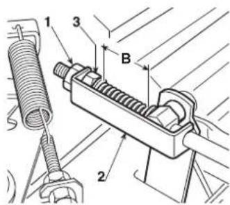
IMPORTANT Do not tighten the screws below these values to avoid overloading the brake unit.
WARNING! If the brake still does not work properly even after this adjustment, immediately contact your dealer. DO NOT ATTEMPT ANY OTHER WORK ON THE BRAKE THAN WHAT IS DESCRIBED HERE.
6.3.5 Adjusting the tension of the drive belt
Should you notice a drop in forward drive power, adjust the tension of the spring of the stretcher to return to former conditions. It is pos
sible to access the adjustment by removing the door located on the tunnel at the base of the seat.
Loosen the locking nuts (2) and unscrew or tighten the screw (1) as needed to obtain a spring length "A" (3) of:
$$
\mathbf {A} = 1 0 9 - 1 1 1 \mathrm {m m}
$$
measured to the outside of the end of the spring. When the adjustment has been made, tighten the nuts (2).
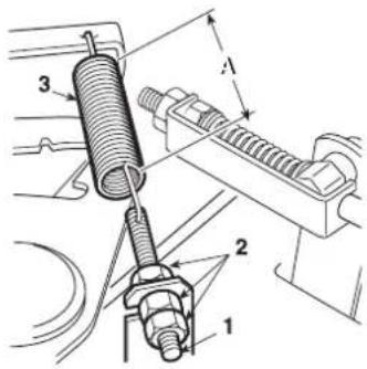
NOTE
When replacing the belt, take great care when
using for the first few times as engagement may be sudden until the belt is sufficiently run in.
6.3.6 Adjusting the grass catcher pawl spring
If the grass catcher tends to move around or open when operating on uneven ground, or if it is difficult to hook on after emptying it, it is necessary to adjust the spring tension (1).
Change the hitch point using one of the holes provided (2) until the desired result is obtained
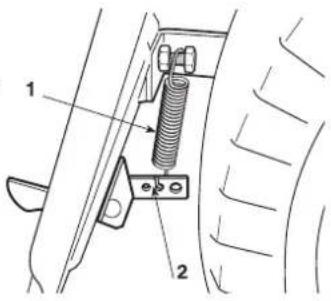
6.4 DISMANTLING AND REPLACEMENT
6.4.1 Engine oil change
Drain the oil when the engine is cold.
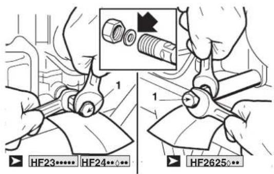
Remove the filler cap with the dipstick and place a sheet of cardboard or a similar object under the drain pipe to prevent oil from dripping onto the machine frame.
Unscrew the cap (1); when reassembling the cap, check the position of the internal seal.
Fill with the recommended oil until the upper limit of the dipstick is reached. (5.3.3). Screw the cap with the dipstick back on.
6.4.2 Changing the oil filter
- Drain the engine oil (6.4.1).
- Remove the oil filter (1) with the filter wrench (2) and drain the remaining oil. Dispose of the oil filter.
-
Clean the filter base (3).
-
Cover the new toroidal seal ring (4) on the new filter with clean engine oil.
- Install the new oil filter on the base of the filter and tighten it by hand until the O-ring is seated against the base of the filter.
- Tighten the oil filter to the specified tightening torque. (12 Nm - 1.20 kgm).
IMPORTANT
Use only an original Honda oil filter or an equivaspecific to your model. Using an unsuitable Honda Honda filter that is not of equivalent quality mayine.
- Fill the engine with the specified amount of recommended oil. Start the engine and check the filter for leakage.
- Turn off the engine and check the oil level again. If necessary, add oil until the appropriate level is reached.
NOTE
- Contact your authorised Honda dealer for advice on each (special tool).
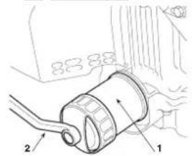
HF2625
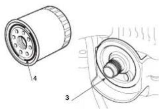
HF23HF24
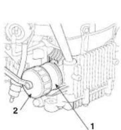
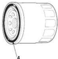
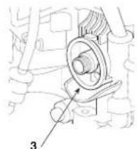
6.4.3 Servicing the air filter
WARNING!
Never clean the air filter with petrol or highly ements. This could cause an explosion or fire.
IMPORTANT
Do not run the engine without the air filter. Foreign
bodies such as dust and dirt could get in and cause the engine to wear out quickly.
1.
HF23

- Remove the two bolts (1a) of the air filter cover from the air filter cover and remove the cover.
Move the paper element (3) from the air filter body (5). Remove
the spongy rubber element (4) from the air filter cover (2).
HF2625
Disengage the two locking tabs (11) from the air filter cover (12).
Unlatch the two tabs (13) from the filter holder (14), then remove the
- filter holder (14) and remove the spongy rubber element (15) from
the holder. Remove the paper element (16).
2. Clean the air filter elements if they are to be reused.
- Spongy rubber element (4-15): clean in warm soapy water, rinse and dry completely. Or clean in a non-flammable solvent and dry. Soak the element with clean engine oil, wringing it out to release excess oil. If too much oil remains on the spongy element, the engine will emit smoke when starting.
- Paper element (3-16): tap the element slightly several times on
a hard surface to remove excess dirt, or blow compressed air (not exceeding 2.1kg / cm^2 through the filter on the side of the air filter body). Do not try to brush away dirt; brushing would introduce dirt into the fibres. Replace the paper element when it is excessively dirty.
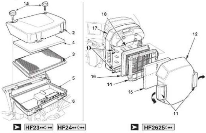
- Wipe off dirt from the inside of the air filter body (5-17) and the cover using a damp cloth. Be careful to prevent dirt from entering the clean chamber (6-18) reaching the carburettor.
- Reinstall the air filter cartridges and cover.
HF23HF24Tighten the two bolts (1a) of the air filter cover firmly.
HF2625Fasten the locking tabs (11) securely.
NOTE Prevent dust, dirt and debris from entering the cleaning chamber (air filter body) during air filter maintenance.
6.4.4 Fuel filter maintenance
WARNING! Gasoline is a highly flammable substance which can explode under certain conditions. Do not smoke or come near the engine with flames or sparks.
Check if any water or sediment has accumulated in the fuel filter (1). If so, take the engine to your authorised Honda dealer.
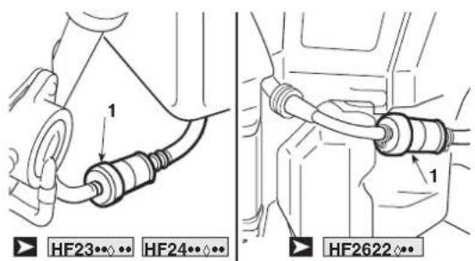
6.4.5 Spark plug maintenance
Recommended spark plugs:
HF23…HF24.…BPR5ES (NGK)-W16EPR-U (DENSO).
HF2625ZFR5F(NGK)
IMPORTANT Never use a spark plug with an unsuitable thermal range.
To guarantee proper engine operation, the spark plug electrode spacing must be correct and the spark plugs must be free of carbon
deposits.
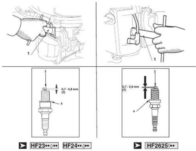
- Remove the spark plug caps and use a spark plug wrench (1) to remove each spark plug.
WARNING! If the engine was running, the muffler is very hot. Be careful not to burn yourself.
- Visually check the spark plugs. Discard the spark plug if it is worn or if the insulator is chipped or cracked. Clean the spark plugs with a wire brush if you want to reuse them.
- Use a thickness gauge to measure the electrode gap (2) of the spark plug, correcting it if necessary by bending the side electrode (3). The gap must be: 0.7 - 0.8mm
- Make sure the spark plug washer (4) is in good condition and screw in the spark plug by hand to avoid damaging the spark plug threads.
- Once the spark plug rests on its base, tighten it with a spark plug wrench (1) in order for it to compress the washer.
NOTE When installing a new spark plug, tighten it 1/2 turn after it is set in order to compress the washer. When reinstalling a used spark plug, tighten it 1/8 1/4 turn until it is in place to compress the washer.
IMPORTANT The spark plugs must be tightened firmly. If the spark plugs are not tightened correctly, they may overheat and damage the engine.
6.4.6 Replacing wheels
Stop the machine on flat ground and put a block under a load-bearing part of the frame on the side that the wheel is to be changed.
The wheels are held by a snap ring (1) which can be removed with a screwdriver.
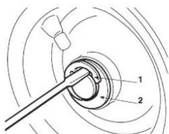
The rear wheels are directly coupled to the differential axle shaft and fastened by a key that forms part of the wheel's hub.
NOTE If you have to replace one or both rear wheels, make sure they have the same diameter, and check that cuttingmeans assembly is horizontal to prevent an uneven cut.
IMPORTANT Before refitting a wheel, smear some waterproof grease on the axle and carefully refit the snap ring (1) and washer (2).
6.4.7 Replacing and repairing tyres
The tyres are of the «Tubeless» type and therefore all puncture repairs will have to be carried out by a tyre-repair expert in accordance with the methods for this kind of tyre.
6.4.8 Replacing bulbs
HF23HF2417HB
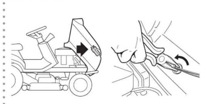
The bulbs (10W) have a bayonet fitting and are installed in the bulb holder which can be taken out by turning it anti-clockwise with pliers.
6.4.9 Replacing a fuse
The machine is fitted with fuses with different capacities and functions, as indicated in the table below:
1 - 10 Amp - (Red) general and power circuit protection of the electronic circuit board;
HF23HF2417HMHF2625HM
2-15 Amp-(Blue) protection of the charging circuit;
HF2417HT· HF2625HT·
2-15 Amp-(Blue) protection of the charging circuit;
3 - 10 Amp - (Red) grass catcher tipping control circuit.
- When the fuse (1) trips, the machine stops and the control panel is completely switched off.
-
When fuse (2) trips, it is shown by the battery warning light( 4.13.f).
-
When fuse (3) trips, the grass catcher tipping control motor will not work.
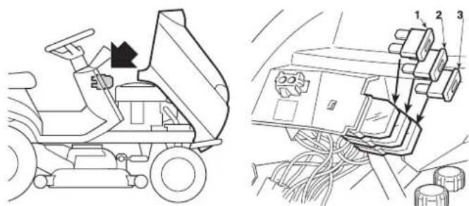
IMPORTANT A blown fuse must always be replaced by one of the same type and ampere rating, and never with one of another rating.
If you are unable to understand why it has blown, contact your dealer.
6.4.10 Replacing the belts
Replacing belts is quite a complicated process of dismantling and subsequent adjustment and must only be carried out by your dealer.
NOTE Replace the belts as soon as they show obvious signs of wear! ALWAYS USE GENUINE REPLACEMENT BELTS!
7. TROUBLESHOOTING
| PROBLEM PROBABLE CAUSE SOLUTION |
| 1. When the ignition key is turned to “ON” the control panel remains switched off without any warning sound. | The safety device of the electronic circuit board has cut in due to:
- badly connected battery
- battery terminals crossed
- completely flat battery or eroded battery plates
- blown fuse
- bad earthing to the engine or the frame | Turn the ignition key to “OFF” position and look for the cause of the problem:
- check connections (±.1)
- check connections (±.1)
- recharge the battery (±6.2.3)
- replace the fuse (10 A) (±6.4.9)
- check connections of black earth wire. |
| 2. When the ignition key is turned to “ON” the control panel remains switched off, but continuous warning sound is activated. | The safety device of the electronic circuit board has cut in due to:
- wet circuit board
- battery voltage too high
- problems with the electronic circuit board | Turn the ignition key to “OFF” position and look for the cause of the problem:
- dry using luke warm air
- Check battery voltage.
- check connections (±3.1)
- replace the battery
- contact your dealer |
| 3. With the ignition key on “START” the control panel light is on, but the starter motor does not run. | - insufficiently charged battery
- badly earthed
- starting conditions have not been met (±5.2) | - recharge the battery (±6.2.3)
- check earth connections
- disengage the cutting means: (check the relative micro switch if the inconvenience persists)
- put the drive into neutral (N)
- sit firmly on the seat |
| 4. With the ignition key on “START” the starter motor runs but the engine does not start. | - insufficiently charged battery
- faulty fuel supply
- faulty ignition
- oil level low | - recharge the battery (±6.2.3)
- check the level in the tank (±5.3.3)
- Check the wiring of the fuel opening solenoid.
- Check the fuel filter (±6.4.4)
- check that spark plug cap is securely fitted (±6.4.5)
- check that the electrodes are clean and have the correct gap between them (±6.4.5)
- Check the engine oil level and top up if necessary (±5.3.3) |
| 5. Starting is difficult or the engine runs erratically | - carburation problems | - clean or replace the air filter (±6.4.3)
- flush out the float chamber (±5.4.13)
- empty the fuel tank and refill with fresh fuel (±4.13)
- check and replace the fuel filter if necessary (±6.4.4) |
| 6. The machine does not start: | - transmission not in neutral (N) with “Cruise Control” not disconnected from the previous use. | - Turn the ignition key to “OFF”
- Disconnect the cruise control device. (±4.9)
Make sure the neutral transmission indicator (N) (4.13,j) lights up on the display.
If the problem persists, please contact your dealer. |
| 7. Weak engine performance during cutting | -forwardspeed too high compared to cutting height(±5.4.5) | - reduce the forward speed and/or raise the height of the cutting-means assembly. |
| 8. The engine switches off when the cutting means is engaged. | - the cutting means engage function lacks consent (±2)
- cutting means engaged in reverse gear | - seat firmly on the seat (if the problem persists, check the relevant microswitch)
- check that the grass catcher or the discharge guard are fitted correctly (if the situation persists, check the relative micro-switch)
- Press the reverse gear cutting consent button (±4.7) |
| 9. The “Cruise Control” device does not engage (activate) | - device components are blocked or damaged | - Turn the ignition key to “OFF”
- Contact your dealer. |
| 10. The “Cruise Control” device does not disengage (deactivate):
- by pressing the mushroom control (4.9)
- by operating the forward drive pedal (4.22)
- by using the brake pedal (4.23) |
| 11. The battery light will not go off after running for a few minutes work | - insufficient battery charge - check connection | |
| 12. The battery light is blinking | - the battery is reaching the overvoltage threshold | - Turn immediately the ignition key to the “OFF” position;
- Disconnect the battery;
- Contact your dealer. |
| 13. The oil lamp lights up while running. | - Engine lubrication problems. Turn immediately | the ignition key to the “OFF” position.
- oil top up (←5.3.3)
- replace the oil filter (if the problem persists, contact your Dealer). |
| 14. - Calibration failed.
The tilt indicators (4.13.l) flash alternatively | - Machine requirements are not met
- time out is happened | - Turn the key to “OFF”, check the machine status and contact your dealer to re-calibrate the sensor. |
| 15. The tilt indicators (4.13.l) often light up incorrectly | - Sensor malfunctioning - Contact your dealer | |
| 16. - The tilt indicators (4.13.l) light up when the surface is flat or on a low gradient. | - driving is not performed safely
- low tyre pressure
- non-calibrated tilting sensor
- problems with the electronic circuit board | - Driving without sudden movements; starting, stopping and steering
- check the tyre pressures
- contact your dealer
- contact your dealer |
| 17. With the ignition key on “ON” position, the USB device does not charge | - badly connected device
- device not connected
- USB cable failure
- USB port temperature too high
- insufficiently charged battery | Turn the ignition key to “OFF” position and look for the cause of the problem:
- Check the device connection
- Check the device connection
- use another USB cable
- wait for the port to cool down and try again
- Check the battery voltage and charging system. |
| 18. The Maintenance Interval code is not displayed when the intervention threshold is reached.
( □ models HF2417*** ) | - battery voltage too high | - check the battery voltage on the display and wait for the voltage value to drop below 12.7V. Then try again |
| 19. The maintenance interval code and the maintenance interval icon cannot be reset even though the engine is off.
( □ models HF2417*** ) |
| 20. Driving times (4.13.a.1) are not recorded.
( □ models HF2417*** ) | - regulator disconnected
- Regulator or electronic circuit board fault | - Check the connection of the regulator
- Check the battery voltage with the engine on If the voltage value is below 12.7V, the fault is with the regulator. If the voltage value is above 12.7V, the fault is with electronic board |
| 21. Driving times (4.13.a.1) are not recorded.
( □ models HF2625*** ) | - engine RPM signal disconnected
- engine or electronic circuit board fault | - Check the connection of the engine RPM signal.
- Check the numerical value and the graphic engine RPM indicator on the display with the engine running. If the numeric value and the graphic indicator are displayed, the fault may be with the electronic circuit board. If both are not displayed, the fault is in the engine. |
| 22. The brightness of the LED main headlight dims during work. | - low battery voltage
- The temperature of the electronic device inside the headlight assembly is too high. | Turn the ignition key to “OFF” position and look for the cause of the problem:
- check the battery voltage and charging system.
- wait a short time Then, restart |
| 23. The LED main headlight does not light up in dark conditions, with the position light (daylight) on. | - connector disconnected
- cable not properly connected
- electronic circuit board problems
- damaged wiring | Turn the ignition key to “OFF” position and look for the cause of the problem:
- check connections and cables
- contact your dealer |
| 24. The position light (daylight) does not switch on | - connector disconnected
- cable not properly connected
- damaged wiring | Turn the ignition key to “OFF” position and look for the cause of the problem:
- check connections and cables
- contact your dealer |
| 25. The engine stops, and a warning sound is activated | The safety device of the electronic circuit board has cut in due to:
- battery contains electrolyte but is not charged
- overvoltage caused by the charge regulator
- badly connected battery (poor contact)
- engine badly earthed | Turn the ignition key to “OFF” position and look for the cause of the problem:
- recharge the battery (6.2.3)
- contact your dealer
- check connections (3.1)
- check engine earth connection |
| 26. The engine stops, without any warning sound. | - battery disconnected
- no gas on the engine
- problems in the engine | - check connections (3.1)
- check engine earth connection
- contact your dealer |
| 27. The cutting means do not engage - slack belt
- electromagnetic engagement problems | - turn the adjuster (6.3.3)
- contact your dealer | |
| 28. Uneven mowing and poor grass collection | - cutting-means assembly is not parallel to the ground
- inefficient cutting means;
- forward speed too high compared to the height of the grass (5.4.5)
- collector channel is blocked
- cutting-means assembly is full of grass | - check the tyre pressure (5.3.2)
- reinstate the alignment of the cutting-means assembly in relation to the ground (6.3.2)
- check that the cutting means is fitted properly (6.3.1)
- sharpen or replace the cutting means (6.3.1)
- check the belt tension and the cutting means engagement lever cable (6.3.3)
- reduce the forward speed and/or raise the height of the cutting-means assembly.
- wait for the grass to dry
- remove the grass catcher and empty the discharge chute (5.4.7)
- clean the cutting-means assembly (5.4.11) |
| 29. Unusual vibrations while operating | - the cutting means are unbalanced
- the cutting means are loose
- loose bolts and screws | - balance or replace the cutting means if damaged (6.3.1)
- check the cutting means fitting (6.3.1)
- check and tighten all the engine and frame bolts |
| 30. With the engine running, the machine does not move when the drive pedal is pressed. | - release lever in position “B” (4.24) | - put into position “A” |
| 31. Difficulty in operating the mulching lever (models HF2417HM - HF-2417HT • HF2625H♦) | - The lever does not move (inconvenience caused by an accumulation of grass in the discharge chute or cutting-means assembly)
- the shutter does not close properly | - remove the material accumulated in the discharge chute or cutting-means assembly
- contact your Dealer. |
If problems persist after having performed the above operations, contact your dealer.
WARNING! Do not take on complicated repair work without the necessary equipment and technical knowledge. The guarantee is automatically revoked and the manufacturer declines all responsibility for any poorly effected repairs.
8. ATTACHMENTS ON REQUEST
1.DISCHARGE
GUARD KIT
80609-VK1-003
Used instead of the grass catcher when the cuttings are not collected.
2.TOWING KIT
80596-VK1-003
For towing a small trailer.
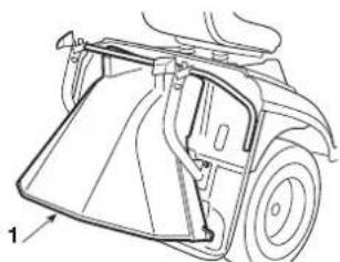
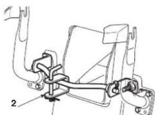
3. MULCHING PLUG AND CUTTING MEANS
HF2317: 80597-VK1-003
HF2417HB:06805-VK1-A10
To finely chop the mown grass and leave it on the lawn, as an alternative to collecting it in the grass catcher.
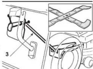
WARNING!
For your safety it is strictly prohibited to fit
any other accessory other than those included in the above
list, they have been exclusively designed for the model and
type of machine you are using..
9. TECHNICAL SPECIFICATIONS
| MODELS HF2317HME HF2417HBE HF2417HME HF2417HTE HF2625HMEH HF2625HTEH |
| Function | |
| Electrical system 12V 12V 12V 12V 12V | | | | | | |
| Battery 24 Ah 24 Ah 24 Ah 24 Ah 24 Ah 24 Ah | | | | | | |
| Engine: HONDA type | GCV530 | GCV530 | GCV530 | GCV530 | GXV690H | GXV690H |
| Cooling system | Air, forced ventilation |
| Number and cylinder configuration (4-stroke) | 2/90°V | 2/90°V | 2/90°V | 2/90°V | 2/90°V | 2/90°V |
| Valves arrangement | OHC | OHC | OHC | OHC | OHV | OHV |
| Total cylinder capacity | 530 cm³ | 530 cm³ | 530 cm³ | 530 cm³ | 690 cm³ | 690 cm³ |
| Effective engine power (*) kW / min-1 | 11,3kW / 3600 | 11,3 kW / 3600 | 11,3 kW / 3600 | 11,3 kW / 3600 | 16,5 kW / 3600 | 16,5 kW / 3600 |
| Engine nominal power kW / min-1 | 9,7 kW / 2800 | 9,7 kW / 2800 | 9,7 kW / 2800 | 9,7 kW / 2800 | 13,9 kW / 2800 | 13,9 kW / 2800 |
| Operating speed min-1 | 2800 min-1 (0,-150) | 2800 min-1 (0,-150) | 2800 min-1 (0,-150) | 2800 min-1 (0,-150) | 2800 min-1 (0,-150) | 2800 min-1 (0,-150) |
| Fuel type | Unleaded petrol E10 |
| Oil capacity | 1.1 litres | 1.1 litres | 1.1 litres | 1.1 litres | 1.7 litres | 1.7 litres |
| Front tyres | 13 x 5.00-6 | 15 x 6.00-6 | 15 x 6.00-6 | 15 x 6.00-6 | 15 x 6.00-6 | 15 x 6.00-6 |
| Rear tyres | 18 x 8.50-8 | 18 x 8.50-8 | 18 x 8.50-8 | 18 x 8.50-8 | 18 x 8.50-8 | 18 x 8.50-8 |
| Front tyre pressure | 1.5 bar | 1.0 bar | 1.0 bar | 1.0 bar | 1.0 bar | 1.0 bar |
| Rear tyre pressure | 1.2 bar | 1.2 bar | 1.2 bar | 1.2 bar | 1.2 bar | 1.2 bar |
| Capacity of the fuel tank | 5.4 litres | 5.4 litres | 8.5 litres | 8.5 litres | 8.5 litres | 8.5 litres |
| Weight unladen (with oil and without fuel) | 221 kg | 243 kg | 245 kg | 256 kg | 267 kg | 276 kg |
| Forward speed | |
| 0 - 8.2 km/h | 0 - 8.2 km/h | 0 - 8.2 km/h | 0 - 8.2 km/h | 0 - 8.2 km/h | 0 - 8.2 km/h |
| in reverse gear | 0 - 4.2 km/h | 0 - 4.2 km/h | 0 - 4.2 km/h | 0 - 4.2 km/h | 0 - 4.2 km/h | 0 - 4.2 km/h |
| Minimum radius of uncut grass | 1.0 m | 1.0 m | 1.0 m | 1.0 m | 0.8 m | 0.8 m |
| Cutting height | 29 ÷ 80 mm | 29 ÷ 90 mm | 29 ÷ 90 mm | 29 ÷ 90 mm | 29 ÷ 90 mm | 29 ÷ 90 mm |
| Cutting width | 92 cm | 102 cm | 102 cm | 102 cm | 122 cm | 122 cm |
| Grass catcher capacity | 280 litres | 300 litres | 300 litres | 300 litres | 350 litres | 350 litres |
| Engaging the grass catcher | manual | manual | manual | electric | manual | electric |
| Dimensions (mm) | |
| A | 1150 | 1150 | 1150 | 1150 | 1150 | 1150 |
| B | 835 | 880 | 880 | 880 | 880 | 880 |
| C | 950 | 950 | 950 | 950 | 950 | 950 |
| D | 1870 | 1870 | 1870 | 1870 | 1870 | 1870 |
| E | 2480 | 2460 | 2460 | 2460 | 2460 | 2460 |
| F | 960 | 1060 | 1060 | 1060 | 1250 | 1250 |
| G | 980 | 990 | 990 | 990 | 990 | 990 |
| H | 1100 | 1120 | 1120 | 1120 | 1120 | 1120 |
| I | 1290 | 1290 | 1290 | 1290 | 1290 | 1290 |
| Carbon dioxide (CO2) emissions (*) | See "CO2 information list" on www.honda-engines-eu.com/co2 |
(^**) CO2 measurement is the result of a fixed cycle test under laboratory conditions of an engine (parent) representing the engine type (engine family) and will not imply or demonstrate the guaranteed performance of a particular engine.
Maximum noise and vibration levels
| MODELS | HF2317HME | HF2417HBE | HF2417HME | HF2417HTE | HF2625HMEH | HF2625HTEH |
| Guaranteed acoustic power level (2000/14/EC, 2005/88/EC) | dB(A) | 100 | 100 | 100 | 100 | 105 | 105 |
| Measured acoustic power level (2000/14/EC, 2005/88/EC) | dB(A) | 100 | 100 | 100 | 100 | 103 | 103 |
| Measuring uncertainty | dB(A) | 0,67 | 0,34 | 0,34 | 0,34 | 0,77 | 0,77 |
| Sound pressure level at the ear(EN ISO 5395-1:2013 + A1:2018 / EN ISO 5395-3:2013 +A1:2017 + A2:2018) | dB(A) | 85 | 85 | 85 | 85 | 89 | 89 |
| Measuring uncertainty | dB(A) | 0,72 | 1,20 | 1,20 | 1,20 | 2,03 | 2,03 |
| Real measured value of acceleration on seat (EN ISO5395-1:2013 + A1:2018 / EN ISO 5395-3:2013 + A1:2017 +A2:2018) | m/s2 | 0,8 | 0,8 | 0,8 | 0,8 | 0,7 | 0,7 |
| Measuring uncertainty | m/s2 | 0,30 | 0,24 | 0,24 | 0,24 | 0,18 | 0,18 |
| Real value of acceleration on steering wheel (EN ISO5395-1:2013 + A1:2018 / EN ISO 5395-3:2013 + A1:2017 +A2:2018) | m/s2 | 2,9 | 3,3 | 3,3 | 3,3 | 3,5 | 3,5 |
| Measuring uncertainty | m/s2 | 1,07 | 0,93 | 0,93 | 0,93 | 0,97 | 0,97 |
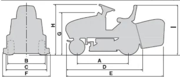
(*) The value of the engine power indicated in this document is the effective power output, tested on the engine of the production models GCV530 and GXV690H, measured according to SAE J1349 at 3600min^-1 (Effective power) and at 2800min^-1 . (Net power). Mass-produced engines may have different values. The power output of the engine mounted on the machine can vary, depending on many factors, including the engine operating speed during use, environmental conditions, maintenance and other variables
10. ALPHABETICAL INDEX
Accelerator Function and use 4.3
Acoustic signal
Function 4.13-o
Intervention 5.4.6
Auxiliary port for USB accessories Function. 4.10
Battery
Description 2.2-7
Connection .3.1
Long periods of disuse 5.4.13
Maintenance and recharging .6.2.3
Brake
Pedal function 4.21
Efficiency control 5.3.4
Brake use 5.4.3
Adjustments 6.3.4
Choke Function and use 4.2
Cleaning Implementing procedures 5.4.11
Cruise control Function and use 4.9
Cutting Hight Adjustment 4.6 Cutting in reverse 4.7 Cutting modes 5.4.5 Cutting end 5.4.9
Cutting advice 5.7
"Mulching" function 5.4.8
Cutting-means assembly Description 2.2-1
Internal washing 5.4.11
Removal 6.3.1-a
Aligning 6.3.2
Cutting means Description 2.2-2 Engagement 4.8 Disassembly and sharpening 6.3.1-b Engagement adjustment 6.3.3
Discharge chute Description 2.2-3 Emptying 5.4.7
Discharge guard Description 2.2-5 Assembly on the machine 5.3.5
Drive pedals
Pedals function 4.22-4.23
Forward drive .5.4.2
Reverse .5.4.4
Engine
Engine oil 6.4.1
Oil filter 6.4.2
Air filter 6.4.3
Fuel filter 6.4.4
Spark plug 6.4.5
Fuse Replacing 6.4.9
Grass catcher
Description 2.2-4
Tipping control 4.11
Assembly on the machine 5.3.5
Emptying 5.4.6
Coupling adjustment 6.3.6
Headlights Ignition control 4.13-i, 4.13-i.1 Lamp replacement 6.4.8
Key Function. 4.4
Maintenance Implementing procedures. 6.1-6.2
Mulching Engagement lever 4.12 Function 5.4.8
Parking brake
Leverage function 4.5
Refuelling Refuelling procedures 5.3.3
Safety
General regulations 1.1
Labels and pictograms 1.3
Device intervention 5.2
Efficiency control 5.3.6
Seat Description 2.2-8 Adjustments 5.3.1
Slops Use Precautions 5.5
Speed change
Forward drive 5.4.2
Reverse 5.4.4
Start-up Start-up procedure 5.4.1
Steering wheel
Function. 4.1
Towing
Instructions 1.4
Transport Implementing procedures 5.6
Tyres Tyres pressure 5.3.2 Repair and replacement 6.4.7
Warning lights Function 4.13
Wheels Replacing 6.4.6
Wheel drive Belt adjustment. 6.3.5
PRÉSENTATION
Cher client,
Honda France Manufacturing S.A.S.
"EC Declaration of Conformity"
CONTENT OUTLINE
1. NORMES DE SECURITE
1.1 CONSIGNES GENÉRALES DE SECURITÉ
ATTENTION! LIRE ATTENTIVEMENT LE MANUEL AVANT D'UTILISER CETTE MACHINE. Conserver pour toute consultation future.
HF2417HB/HM HF2625HM
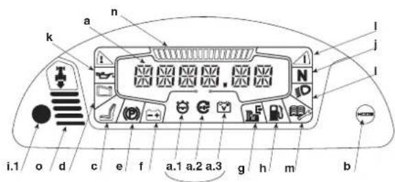
HF2417HT· HF2625HT
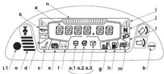
These Maschine woke up in the morning, and he had to go to the inn. He was a man of strong personality, with a good sense of humor. He had been born in Germany, but his family did not know him. He had been born in Austria, but he had never been there before. He had been born in France, but he had never been there before. He had been born in Italy, but he had never been there before. He had been born in Spain, but he had never been there before. He had been born in the United States, but he had never been there before. He had been born in the United States, but he had never been there before. He had been born in the United States, but he had never been there before. He had been born in the United States, but he had never been there before. He had been born in the United States, but he had never been there before. He had been born in the United States, but he had never been there before. He had been born in Italy, but he had never been there before. He had been born in Italy, but he had never been there before. He had been born in the United States, but he had never been there before. He had been born in the United States, but he had never been there before. He had been born in the United States, but he had never been there before. He had been born in the United States, but he had never been there before. He had been born in the United States, but he had never been there before. He had been born in Germany, but he had never been there before. He had been born in Germany, but he had never been there before. He had been born in Germany, but he had never been there before. He had been born in Germany, but he had never been there before. He had been born in Germany, but he had never been there before. He had been born in Germany, but he had never been there before. He had been born in Germany, but he had never been there before.
Honda France Manufacturing S.A.S.
Honda France Manufacturing S.A.S.
"EC Declaration of Conformity CONTENT OUTLINE
1. NORME DI SICUREZZA
1.1 NORME GENERALI DI SICUREZZA
HF2417HB/HM HF2625HM
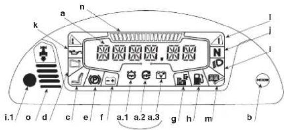
HF2417HT· HF2625HT·
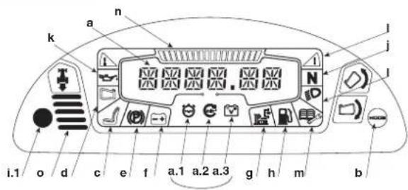
5.4 USO DELLA MACCHINA
5.4.1 Avviamento
6.2.1 GUIDA ALLA MANUTENZIONE PROGRAMMATA
m = 311
Honda France Manufacturing S.A.S.
"EC Declaration of Conformity CONTENT OUTLINE
HF2417HB/HM HF2625HM
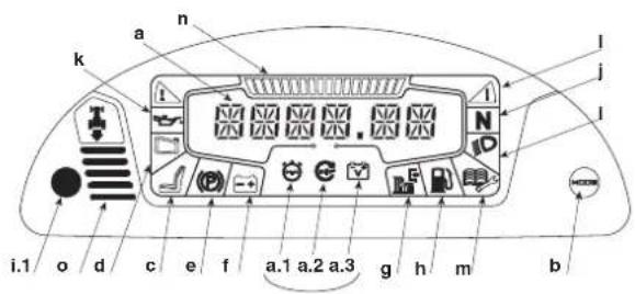
HF2417HT· HF2625HT

Modo deexecution 5.6
Volante
FunciON 4.1
UVOD
Vázény zákaznik,
Honda France Manufacturing S.A.S.
(P) "B" = Brzda zapojená
- Brzda sa aktivujé uplnym stlačenim pedalu (4.21) a prepnutim páky do polohy "B". Ked potom pustite nohu z pedalu, páka brzdy zestane zablokovaná v dolnej polohe.
- Stav "Brzda zapojená" je znázorneny rozsvietenim kontrolky (4.13.e).
- Pre odbrzdenie parkovacej brzdy stlacte pedal (4.21). Páčka sa vrati do polohy "A".
4.6 PÁKA NASTAVENIA VÍŠKY KOSENIA
Vythnute = Zacie zariadenie zapojené
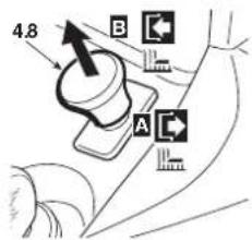
- Stav "Zacie zariadenie zapojene" je indikovany ked' sa rozsvieti indicator (4.13.g).
- Ak spustite zacie zariadenie bez splenia bezpečnostnych podmienok, motor sa zastavi a nedá sa naşartovat (5.2).
- Pri odpojen ziacich nozov (poloha "A"), sa sucasne aktivuje brzda, ktora zastavich rotaciu v priebehui niedk.
- Spustit Žacie zariadenie v spātnom chode je moźne iba stlacenim tlacidla 4.7.
4.9 TEMPOMAT

HF2417HM
HF2417HT
HF2625H
Toto zariadenie udrzuje stroj na pozadovanej rychlosti jazdy bez toho, aby bolo potrebne tlacit pedal (4.22).
Tlaicidlo tvaru hriba ma dve polohy:

- "A" = Zatlačený. Zariadenie odpojené (vypnuté)
- "B" = Vytilhnuty. Zariadenie zapojene (zapnuty)

Ak zapnete zariadenie pochas jazdy, stroj si udrziy rychlost dosiahnutu v tom case bez toho, abi ste museli tlaicit pedal (4.22).
Zariadenie sa nemoze pouzit pri spatnom chode.
- Ked' je zariadenie zapojene, nie je mozné ovlad' pedal spatneho chodu (obr. 4.23).
- Pri usekoch do kopca alebo z kopca sa rychlost moze liisit od rychasti nastavenej na rovnom povrchu.
Na vypnutie zariadenia a resetovanie ovladanie rychlosti pedalom (4.22), Jednoducho
stlactepedal4.22
alebo
- stlacte brzdvoy pedal (4.21).
V ooboch pripadoch sa tlacidlo tvaru hriba automaticky vrati do polohy "Stlacene".
4.10.a PRIDAVNY VYSTUP PRE PRISLUSENSTVO USB

HF2417HM· HF2417HT· HF2625H
Tento vystup moze nabijat USB zariadenia. Pouziva sa iba na nabijanie.
Tento vystup nema ziadnu komunikačnu funkciu so zapojenym USB zariadenim.

Vystup je zivy iba
ked' je kl'uc (4.4) v polohe "ZAPNUTY".
Zariadenia USB nabijaje pri spustenom motore, aby sa predislo vybitiu baterie.
Nenabijaje USB prisluesentvo vo vhlkych podmienkach alebo za dazd'a. Ak by ste nabijali v tchyto podmienkach, zaruka straca platnost a vyrobca nezodpoveda za ziadne problemy.
Neotvárajte zatku USB za dažda ani v prašnom prostredí.
Honda France Manufacturing S.A.S.
3.4 MONTERA SPAKARNA FÖR ATT TIPPA GRÄSUPPSAMLAREN

HF2…HT
4.6 JUSTERINGSSPAK FÖR KLIPPHÖJD
=Knivarna avaktiverade


"B"Utdragen=
Knivarna aktiverade
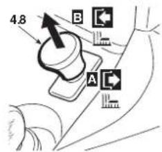
HF2417HB/HM· HF2625HM

HF2417HT· HF2625HT·
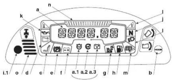
MINSKA HASTIGHETEN INNAN DU ANDRAR
(Estonia / Latvia / Lithuania)
NGC Import Baltics OU
Meistri 12
Haabersti District
3517 Tallinn
Harju County Estonia
Tel.: +372 651 7300
Fax:+3726517301
info.baltic@ncgimport.com
BELARUS
UAB JP Motors
Montazhnikov Lane 4th,5-16
Minsk 220019
Republic of Belarus
Tel.: +375172349999
Fax:+375172380404
honda@jpmotors.lt
BELGIUM
Honda Motor Europe Ltd
Doornveld 180-184
1731 Zellik
Tel.: +32 2620 10 00
Fax:+3226201001
http://www.honda.be
bh_pe@honda-eu.com
BULGARIA
Premium Motor Ltd
Andrey Lyapchev Blvd no 34
1797 Sofia
Bulgaria
Tel.: +35924235879
Fax: +3592 423 5879
http://www.hondamotor.bg
office@hondamotor.bg
CROATIA
Hongoldonia d.o.o.
Vukovarska ulica 432a
31000 Osijek, HR
Tel.: +38531320420
Fax: +38531320429
http://www.hongoldonia.hr
prodaja@hongoldonia.hr
CYPRUS
Demstar Automotive Ltd
Mihail Giorgalla 14
2409 Engomi
Nicosia
Cyprus
Tel.: +357 22 792 600
Fax:+35722430313
CZECH REPUBLIC
BG Technik cs, a.s.
U Zavodiste 251/8
15900 Prague 5 - Velka
Chuchle
Tel.: +420 2 838 70 850
Fax: +420 2667 111 45
http://www.honda-stroje.cz
DENMARK
Tima A/S
Rytermarken 10
DK-3520 Farum
M50 Business Park, Ballymount
Dublin 12
Tel.: +353 1 4381900
Fax:+35314607851
http://www.hondaireland.ie
品 sales@hondaireland.ie
ISRAEL
Mayer's Cars and Trucks Co.Ltd.
Honda Division
Shevach 5, Tel Aviv, 6777936
Israel
+972-3-6953162
OrenBe@mct.co.il
ITALY
Honda Motore Europe Ltd
Makpetrol A.D. Honda Centar
Bulsv Kiril & Metodijbr.4
1000, Skopje
Republic of Macedonia
念 aleksandar.stanojlovic@
makpetrol.com.mk
MALTA
The Associated Motors
Company Ltd.
New Street in San Gwakkin Road
Aries Power Equipment
Pulawska 467
02-844 Warszawa
Tel.: +48 (22) 861 4301
Fax:+48(22)8614302
http://www.ariespower.pl
AS Domzale Moto Center D.O.O.
Blatnica 3A
1236Trzin
Tel.: +386 1562 3700
Fax:+38615623705
http://www.honda-as.com
品 infomacije@honda-as.com
AIN & all provinces
Greens Power Products, S.L.
Poligono Industrial Congost
Av. Ramon Ciurans n°2
08530 La Garriga - Barcelona
Tel.: +34 93 860 50 25
Fax: +34 93 871 81 80
http://www.hondaencasa.com
SWEDEN
Honda Motor Europe Ltd
filial Sverige
Box 31002-Langhusgatan 4
215 86 Malmö
Tel.: +46 (0) 40 600 23 00
Fax: +46 (0) 40 600 23 19
http://www.honda.se
hpesinfo@honda-eu.com
SWITZERLAND
Honda Motor Europe Ltd,
Succursale de Satigny/Genève
Rueda Bergere 5
1242 Satigny
The unsigned, *2, representing the manufacturer, herewith declares that the machinery described below fulfils all the relevant provisions of:
Directive 2006/42/EC on machinery
Directive 2014/30/EU on electromagnetic compatibility Directive 2000/14/EC-2005/88/EC on outdoor noise
Directive 2011/65/EU - (EU) 2015/863 on the restrictions
substances in electrical and electronic equipment
- Description of the machinery
(a) Product: Ride-on lawn
b) Function: Cutting of grass
| c) Model | d) Type | e) Serial number |
| *1 | *1 | |
Manufacturer and able to compile the technical documentation
Honda France Manufacturing S.A.S.
- Outdoor noise Directive
a) Measured sound power dB(A): *1
b)Guaranteed sound power dB(A): *1
c) Noise parameter (cm, min-1): *1
d) Conformity assessment procedure: *2
e) Notified body: *2
100 : 101 × 100
Done at: OR
( x - 2x) t - xy^2 = ( x - 2x) f^ t
2
President
Wu Wei 11:40 a.12
Honda France Manufacturing S.A.S.
| Slovenscina (Slovak)Slovenscina (Slovenian)ES zjiva o skladnosti1. Dolupodispanyan pǎn 2'zastupujiciy výrobu tymovyhyasúka, ze uvedeny stróvo je v zhode snaslévovní smirničami:2. Smerica 2006/42/ES (Stojne zariadenia)3. Smerica 2000/14/ES - 2005/88/ES (Emisie huku)4. Rady 2011/65/EU - (EU) 2015/863 o obmedzeni použovania urichtyne nebepežnéch yaskov tečkých a elektronickych zariadienach2. Popis strojaa)Product: Kosaša so sediacou obshluoubajFunkcia: Kosenie trávyC model d: Typ e) Vyrobé nátečla3. Vyrobača a schopny zostavil technická dokumentácu4. Referência na použité normy5. Smerica pre emisie huku va volnormi pristavstvoa)Namaroná hladna akustického vykouna6. RoznerD. Procedura posudzovania zhodye7. Mesto 7. Datum | Eesti (Estonian)EU vostavusdeklaratiom1. Aliakirutanu, 2' kinnitab totojat volatud indesanjana, at allspool kiregulad masina vaskablikskolele aljagngneval direktivldssettle:3. Masteinat direktiv 2006/42/EO4. Elektragnelline ühludvus direktiv 2014/30/ELVämslarmia direktiv 2004/14/EU - 2005/88/EBdikrivt 2011/65/EL - (EL) 2015/883 tevatlatovi onhtale anite kasetumil pamirame kohta elektrár-ja elektroninkaseadmetres2. Seadmele kirejdusa)Toode: Muruniduk - traktorb4. Funkcioc: kosjenje trave3. Toodja,kes on padev lalita lehnlist Dokumentatiocn4. Vilek kohladut standarditele5. Vallismir direktiv4. Møldelud helvidimuse laseb)Lubalud helvidimuse lasec)Mura parametochotovontkrd | Slovenscina (Slovenian)ES zjiva o skladnosti1. Spodaj podispani, 2' k predstavljam prozvažilac, izjavajam da podispani opasnja stroz uzmaz vsm navedenim direktiv3. Direktiva 2006/42/ES o stejnij3. Direktiva 2004/14/EU - 2005/88/ES o hrupnost3. Direktiva 2011/65/EU - (EU) 2015/863 oomejavanjuporapabe nekaterih nevamih snovi v elektrónicn in elektronik opremi3. Ops napravap)Prozvoj: Kosilinca s sedežem3. Funkcioc: kosjenje trave3. Model d: Tip e) Sanjska slytrojovnichko
a) Umaraná hladna akustického vykouna
b) Zaručné na akustickéno vykouna
c) Rozmer
d) Procedura posudzovania zhodye
e) Notlukovná osoba
6. Mesto 7. Datum | Norsk (Norwegian)EF-Samsvarskiering1. Undertegnoda. 2' representer der producerilen og ordinar erkränker at maskinori beskovoy nedonfor infirr relevant information faglende skriftern3. Maskindirektiv 2005/42/EF3. Direktiva 2014/30/EU om Elektragneliskkapablity3. Direktiv on stay undaten 2000/14/EF - 2005/88/EF3. Direktiv on stay undaten 2000/14/EF - 2005/88/EF3. Reskissjönser av bruk av visse farlige malnärer i elektrig od elektronik usyt3. Beskrivlase av produk
a) Projekt: Gresskipper som operator sitter pa og kjer3. Funkcj: Klipe gress3. Model d: Typ e) Seriennummer3. Producent og i stand til a utarbe de n tenkiste
dokumentasiya
4. Brednaya zukovovnichko
5. Garantuzjans garso galinguma lygis
6. Tridas
7. Data | Hvatski(Croatian)EK Pizava o sukradnosti1. Pizaspani, 2' imo prozvažić, ovime izjavijije da strjevji vnedeni un nastavku ispunjavju vsevacice odredne;
Propisa za strjovje 2006/42/EK
Propisa 2014/30/EU na elektronarnska komplisibilnost
Propisa o buci na otvorenome 2000/14/EK - 2005/88/EK
Propisa o buci na otvorenome 2000/14/EK - 2005/88/EK
Ognaričenji od radjenih opasnih supstanu i elektrkovi od elektronskoj opremi.
2. Opis strjovej
a) Prozvod: Kosilce trive s rukovateljem koji sjetdi na kosili di Functionalnonost
b) Model d: Tip e) Seriennummer
3. Teknik dosyav hazarnackla yeklii olan
Topluklia yereşik Imataki
4. Uygulanan standartla istladen
5. Alok ani gurluti ynetmeli
6. Makineni tanifi
a) Orliu Sürüdu oturkiqim cimi michekinesi
b) Isglev: Cimetirin koslimisi
c) Model d: Tip e) Seriennummer
3. Teknik dosyav hazarnackla yeklii olan
Topluklia yereşik Imataki
4. Uygulanan standartla istaden
5. Alok ani gurluti ynetmeli
6. Makineni tanifi
a) Orliu Sürüdu oturkiqim cimi michekinesi
b) Isglev: Cimetirin koslimisi
c) Model d: Tip e) Seriennummer
3. Teknik dosyav hazarnackla yeklii olan
Topluklia yereşik Imatki
4. Uygulanan standartla istaden
5. Alok ani gurluti ynetmeli
6. Makineni tanifi
a) Orliu Sürüdu oturkiqim cimi michekinesi
b) Isglev: Cimetirin koslimisi
c) Model d: Tip e) Seriennummer
3. Teknik dosyav hazarnackla yeklii olatan
Topluklia yereşik Imatki
4. Uygulanan standartla istaden
5. Alok ani gurluti ynetmeli
6. Makineni tanifi
a) Orliu Sürüdu oturkiqim cimi michekinesi
b) Isglev: Cimetirin koslimisi
c) Model d: Tip e) Seriennummer
3. Teknik dasyav hazarnackla yeklii olatan
Topluklia yereşik Imatki
4. Uygulanan standartla istaden
5. Alok ani gurluti ynetmeli
6. Makineni tanifi
a) Orliu Sürüdu oturkiqim cimi michekinesi
b) Isglev: Cimetirin koslimisi
c) Model d:
3. Teknik dasyav hazarnackla yeklii olatan
Topluklia yereşik Imatki
4. Uygulanan standartla istaden
5. Alok ani gurluti ynetmeli
6. Makineni tanifi
a) Orliu Sürüdu oturkiqim cimi michekinesi
b) Isglev: Cimetirin koslimisi | Hvatski(Croatian)
EK Pizava o sukradosti1. Pizaspani, 2' imo prozvažić, ovime izjavijije da strjevji vnedeni un nastavku ispunjavju vsevacice odredne;
Propisa za strjovje 2006/42/EK
Propisa 2014/30/EU na elektronarnska komplisibilnost
Propisa o buci na ot vorenome 2000/14/EK - 2005/88/EK
Ognaričenji od radjenih opasnih supstanu i elektrkovi od elektronskoj opremi.
2. Opis strjovej
a) Prozvod: Kosilce trive s rukovateljem koji sjetdi
a) Zemiuska zukovovnichko
b) Zajaměska zukovu
b) Parametern buke
b) Postupak za ocjenu suddanstnoi
c) Obvjesteno tijelo
6. U 7 Datum |
| Svenska (Swedish)EG-forskärn och överensstämme | Espanol (Spanish)Declaración de Conformidad CE1. El firmante, "2, en representation del fabricante, adjunto descripción que laquina abajo descritúa, cumple las cláulas relevantes de:·Directiva 2006/42/CE de maquárnia·Directiva 2014/30/UE selecarnetiskkompatibilitet·Directiva 2000/14/EG - 2005/88/EG gällande bullorutomnis·Directiv 2011/65/EU - (EU) 2015/863 ombegrānsing av använding av vissa fariga armeni elektrik och elektronik utrustning2. Maskinbeskrivninga) Product: Akgåskilpparebfunktive och skunna sammanställa teknik documentingarien.4. Referens for tillampad standard5. Direktiv for bullerulomhusa) Upomatt ljdrivá·Garantendar ljdrivá·Buller parameterd) Forlarande for bedörninge) Annidala organ6. Uffardat vid 7. Datum | Romàna (Romanian)CE- Declarazione de Conformitate1. Subsenmatul "2, representand producutorul, declar prin prenta duplat cale illiecapire desciunt malos indiplenste totale condillo necessare din:·Directiva 2006/42/CE privid echipamentul·Directiva 2014/30/UE selecarnetiskompatibilitet·Directiva 2000/14/CE - 2005/88/CE du ridoexterior·Directiva 2011/65/EU - (UE) 2015/863 sobrerestriciones a la utilización de determinadasusistancias poligrosas on aparatos electrícos yelectriconos2. Descripción de la maquinaa) Product: Cortacasped de asientob) Function : Cortacarped de asientob) Function : Cortacarped de asientob) Function : Cortacarped de asientob) Function : Cortacarped de asientob) Function : Cortacarped de asientob) Function : Cortacarped de asientob) Function : Cortacarped de asientob) Function : Cortacarped de asientob) Function : Cortacarped de asientob) Function : Cortacarpod de asientob) Function : Cortacarpod de asientob) Function : Cortacarpod de asientob) Function : Cortacarpod de asientob) Function : Cortacarpod de asientob) Function : Cortacarpod de asientob) Function : Cortacarpod de asientob) Function : Cortacarpod de asientob) Function : Cortacarpod de asientob) Function : Cortacarpodde asientob) Function : Cortacarpodde asientob) Function : Cortacarpodde asientob) Function : Cortacarpodde asientob) Function : Cortacarpodde asientob) Function : Cortacarpodde asientob) Function : Cortacarpodde asientob) Function : Cortacarpodde asientob) Function : Cortacarpodde asientob) Function : Cortacarpoddeas | Suomi / Suomen kiell (Finnish)EY-VAAT MUSTENMUKAIUSUVAKUUTUS1. Allokirjotanl mutvalintan odustaja 2 vukuvaa tali, et al. mainitau kone/tuole tayttä kaikkseura määräysäk;·Konedirektiva 2006/42/EE·Directiva 2014/30/UE sähkormagnetoletinenyhtensopius·Directiva 2000/14/EE - 2005/88/EE ympärisänmelu·Directiva 2011/65/EU - (EU) 2015/863 betlyjanvaarallisten aineden käytön mäjittamisesta sähköjaelektronikkalalileissaa.TUOTTEEN KUVAUSa) Tucie: Ajetava ruchoniekkurib) Tominto: ruhson lekkausb) Mall d TYPPPI a) SARJANUMERO3. Valmistaja ja tekinsten dokumentten laita4. Vittaus sovelletuih in standardehin5. Ympairstön maludirektivamii) Mitatu melutasoTodenmuikainen melutasoMelu parametrii6. Yhdernmuksiuden anviominn menelmaItektonantoolin6. TEHTY 7. PAVAMAAR |
| Portugues (Portuguese)Declaração CE de Conformidade1. O não係ado, declara que a maquina a boaço descritta,cumpuito todas as espéculações relevantes da:·Directiva 2006/42/CE de maquira·Directiva 2014/30/UE relativa à compatibilidade electromagnética·Directiva 2000/14/CE - 2005/88/CE de rudoexterior·Directiva 2011/65/EU - (UE) 2015/863 relativa àprocedimento do uso de determinadasubestancias perigosas em equipartimentos electricos eelecricionales2. Descrição da maquinaa) Product: Corra reva com operador transportadob) Função : corde de relvaModelo d) Tipo e)Numero de série3. Fabricante com capacidade para compilarDOCUMENTação lécricia4. Referência as normas aplicadas3. Fabricante com capacidade de compilar documentação lécricia5. Directiva de rudo exteriora) Polência sonora medidab) Polência sonora garantidac) Parametro de rudoProcedimento de avaliação da conformidadee) Organismo notificado6. Feito em 7. Datum | Polski (Polish)Deklaracja Zgodnoszne WE1. Nízi podpisamy "2, reprezentujagcy produktona, ninejsym agrdianje, ze uzragzenia opisaneponižej spelina wsziekie wólwocie postanowsianie:Dyroktwy maszymowny 2004/42/WE·Dyroktwy 2014/30/UE KompatablońskiodekromagnetznejDyroktwy Hatasowa 2000/14/WE - 2005/88/WEZyprawie agrizoczenia stochonji w sprępiecie elektrycznymi i elektryczonymi2. Opis uzragzenia:a) Product: Kosiarka traktorowa z siedziskiem dl aperatororab) Funkja: sciananie trawyModelo d) Typ e) Numer serjiny3. Producent oraz osoboa upoważnióda por przygolovania documentskomentziejPrzydarytka Hatasowaa)Zmerzoryn pozium mocy akustyczneybGwarantowy pozium mocy akustyczneycWartosi halasiDu procedure oceny zgodnoscieJednostska nolitykowana6. Miejsoe7. Datum | Latviešu (Latvian)EK stbstibas delekradaciya1. Zenak minétsa "2, ka razotajpa rastväis ar soapiatipina, ka zemakrapskrliffe maška, atbsti visžem zemak nordafio direktrva sadaljärn:·Directiva 2006/42/EE parokmianl mazinam, atbsti visžem zemak nordafio direktrva sadaljärn:·Directiva 2014/30/EE parokmianl perskoviško saderibu:·Directiva 2000/14/EE - 2005/88/EE parokmianl emisiju videa·Directiva 2011/65/EU - (ES) 2015/863 par dazu bistamu viiu zimontanosanierobežošanuelektrikas un elektronikskais ekkäras2. lekáratsApraksbAs Products: Zales plaješi traktorsbuktiFunkcjä: zélevagácsbModel d) Tip e) Sorozatszám3. Gydóró é pékes ayanogkótes elektrómos es elektronikus berendezeseken bival alkalmazăsänakkordiózászlade2. A gép leirásaa) Temkě: Fényiro traktor, rátolsb) Funko: fí levágázsbcModel d) Tip e) Sorozatszám3. Gydóró é pékes ayanogkótes elektrómos es elektronikus berendezeseken bival alkalmazăsänakkordiózászlade2. Fágyőz hógyérősztátszászlade4. Referência ac alkalmazott szabványokozhao5. Koltárszalszinti Direktrivaa Mertékő pro húk pro venkovnì pôzítAlaibai hangófSzavavolthangörld) Szavavolt hangörld) Zajciszinti parameterd) Megtefalósegi beçséslái eljáras6. Kőlétő szevetzel | Látriešu (Latvian)EK stbstibas delekradaciya1. Zenak minétsa "2, ka razotajpa rastväis ar soapiatipina, ka zemakrapskrliffe maška, atbsti visžem zemak nordafio direktrva sadaljärn:·Directiva 2006/42/EE parokmianl muzinam, atbsti visžem zemak nordafio direktrva sadaljärn:·Directiva 2014/30/EE parokmianl perskoviško saderibu:·Directiva 2011/65/EU - (ES) 2015/863 par dazu bistamu viiu zimontanosanierobežošanuelektrikas un elektronikskais ekkäras2. lekáratsApraksbAs Products: Zales plaješi traktorsbuktiFunkcjä: zélevagázsbcModel d) Tip e) Sorozatszám3. Gydóró é pékes ayanogkótes elektrómos es elektronikus berendezeseken bival alkalmazăsänakkordiózászlade2. A gézáča zélevagázsbcModel d) Tip e) Sorozatszám3. Gydóró é pékes ayanogkótes elektrómos es elektronikus berendezeseken bival alkalmazăsänakkordiózászlade2. Fágyőz hógyérősztátszászlade4. Referência ac alkalmazott szabványokozhao6. Koltárszalszinti Direktrivaa Mertékő pro húk pro venkovnì pôzítAlaibai hangófSzavavolthangörld) Szavavolt hangörld) Zajciszinti parameterd) Megtéfalósegi beçséslái eljáras6. Koltárszalszinti Szegedyözcskóf | Zármatajka (Czech)Elschneckováho Žovce "2, smy podismem potrovze, zhe šrho popany na zhe spilupfe na protadyzkávo je protéctumovcýte opacifieniPrážováte zékůtek"Prážováte zékůtek"Prážováte zékůtek"Prážováte zékůtek"Prážováte zékůtek"Prážováte zékůtek"Prážováte zékůtek"Prážováte zékůtek"Prážováte zé |
HONDA