
SIH 20TE - Water pump DIMPLEX - Free user manual and instructions
Find the device manual for free SIH 20TE DIMPLEX in PDF.
| Product Type | Brine-water heat pump for indoor installation |
| Model | SIH 20TE |
| Brand | Dimplex |
| Dimensions (H x W x D) | 1660 x 1000 x 750 mm |
| Weight (including packaging) | 307 kg |
| Power supply | 400 V / 25 A (3 phases + N + PE) |
| Protection | IP 21 |
| Nominal heat output | 20 kW (for average climate conditions) |
| COP (B0/W35) | 4.7 (2 compressors) / 4.4 (1 compressor) |
| Max. flow temperature heating water | 70 °C |
| Heat source temperature range (brine) | -5 °C to +25 °C |
| Refrigerant | R134a, 4.2 kg, GWP 1430 |
| Heating connections | G 1 1/4" (internal/external) |
| Heat source connections | G 1 1/2" (internal/external) |
| Main functions | Space heating, domestic hot water production (with external tank), integrated controller management |
| Controller | Integrated heat pump manager with display, remote control capability and Modbus/KNX/Ethernet interface |
| Maintenance | Clean condenser with 5% phosphoric acid; clean heat source side filter after 1 day then as needed based on fouling |
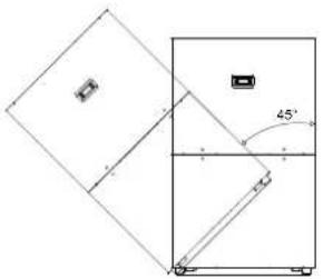
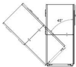
| Safety | Frost protection, mandatory flow switch for external control, motor circuit breaker, max. tilt angle 45° |
| Spare parts and accessories | Connection flanges, remote control, interface card for building management, calorimeter WMZ, outdoor sensor kit, filter |
| General information | Indoor installation, CE compliant, HCFC-free refrigerant, sound level 62 dB(A) |
Frequently Asked Questions - SIH 20TE DIMPLEX
User questions about SIH 20TE DIMPLEX
0 question about this device. Answer the ones you know or ask your own.
Ask a new question about this device
Download the instructions for your Water pump in PDF format for free! Find your manual SIH 20TE - DIMPLEX and take your electronic device back in hand. On this page are published all the documents necessary for the use of your device. SIH 20TE by DIMPLEX.
USER MANUAL SIH 20TE DIMPLEX
natural_image
Line drawing of a rectangular industrial cabinet or enclosure with mounting feet and a lid (no text or symbols)Installation and Operating Instruction
Brine-to-Water Heat Pump for Indoor Installation
natural_image
Technical line drawing of a refrigerator with 45-degree angle标注 (no text or symbols beyond basic geometry)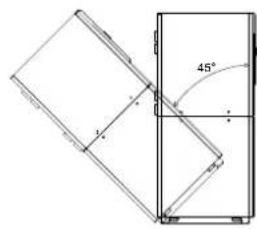
natural_image
Technical line drawing of a folding panel with 45-degree angle标注 (no text or symbols beyond measurement)ACHTUNG!
natural_image
Pure technical diagram of a mechanical assembly with no visible text, numbers, or symbolsGlen Dimplex Thermal Solutions
Garantieurkunde GDTS
Glen Dimplex Thermal Solutions
natural_image
Empty white rectangle with black border (no text or symbols)Table of contents
1 Read immediately....EN-2
1.1 Important Information......EN-2
1.2 Intended Use......EN-2
1.3 Legal Provisions and Guidelines ......EN-3
1.4 Energy-Efficient Use of the Heat Pump......EN-3
2 Purpose of the heat pump ......EN-3
2.1 Application ......EN-3
2.2 Principle of Operation......EN-3
3 Baseline Unit......EN-4
4 Accessories......EN-4
4.1 Connecting Flanges....EN-4
4.2 Remote control......EN-4
4.3 Building management technology....EN-4
4.4 Thermal energy meter WMZ ......EN-5
5 Transport......EN-5
6 Installation....EN-6
6.1 General Information......EN-6
6.2 Sound Emissions......EN-6
7 Mounting......EN-6
7.1 General Information......EN-6
7.2 Connection on Heating Side......EN-6
7.3 Connection on Heat Source Side......EN-7
7.4 Temperature sensor....EN-7
7.5 Electrical connection....EN-9
8 Commissioning......EN-10
8.1 General Information......EN-10
8.2 Preparatory Steps......EN-10
8.3 Commissioning Procedure....EN-10
9 Care/Cleaning......EN-10
9.1 Care....EN-10
9.2 Cleaning of Heating Side......EN-10
9.3 Cleaning of Heat Source Side......EN-10
10 Malfunctions / Troubleshooting......EN-11
11 Decommissioning / Disposal......EN-11
12 Equipment Data......EN-12
13 Product information as per Regulation (EU) No 813/2013, Annex II, Table 2...... EN-13
Anhang / Appendix / Annexes ...... A-I
Maßbild / Dimensioned drawing / Schéma coté ...... A-II
Diagramme / Schematics / Diagrammes....A-III
Stromlaufpläne / Wiring diagrams / Schémas électriques ...... A-V
Hydraulisches Einbindungsschema / Hydraulic integration diagram /
Schéma d'intégration hydraulique ....A-IX
Konformitätserklärung / Declaration of Conformity / Déclaration de conformité ....A-XI
1 Read immediately
1.1 Important Information
ATTENTION!
When operating or maintaining a heat pump, the legal requirements of the country where the heat pump is operated apply. Depending on the refrigerant quantity, the heat pump must be inspected for leaks at regular intervals by a certified technician, and these inspections must be recorded.
ATTENTION!
Any work on the heat pump may only be performed by an authorised and qualified customer service.
ATTENTION!
If the heat pump or circulating pumps are controlled externally, an flow rate switch is required to prevent the compressor from being switched on when there is no volume flow.
ATTENTION!
The heat pump must not be tilted more than max. 45^ (in either direction).
ATTENTION!
The transport securing devices must be removed prior to commissioning.
ATTENTION!
The heating system must be flushed prior to connecting the heat pump.
ATTENTION!
With fully demineralized water, it is important to ensure that the minimum permissible pH value of 7.5 (minimum permissible value for copper) is complied with. Failure to comply with this value can result in the heat pump being destroyed.
ATTENTION!
The supplied strainer must be fitted in the heat source inlet of the heat pump in order to protect the evaporator against the ingress of impurities.
ATTENTION!
The brine solution must contain at least 25 % of an antifreeze agent on a mono-ethylene glycol or propylene glycol basis and must be mixed prior to filling.
ATTENTION!
Ensure the rotary field is clockwise when connecting the mains cables (if the rotary field is not clockwise, the heat pump will not work properly, is very loud and may cause damage to the compressor).
ATTENTION!
It is not permitted to connect more than one electronically regulated circulating pump via a relay output.
ATTENTION!
Start-up must be performed in accordance with the installation and operating instructions of the heat pump manager..
ATTENTION!
To prevent the accumulation of deposits (e.g. rust) we recommend using a suitable corrosion protection system.
ATTENTION!
Disconnect all electrical circuits from the power supply before opening the enclosure.
1.2 Intended Use
This device is only intended for use as specified by the manufacturer. Any other use beyond that intended by the manufacturer is prohibited. This requires the user to abide by the relevant project planning documents. Please refrain from tampering with or altering the device.
1.3 Legal Provisions and Guidelines
This heat pump is designed for use in a domestic environment according to Article 1, Paragraph 2 k) of EC directive 2006/42/EC (machinery directive) and is thus subject to the requirements of EU directive 2014/35/EU (low-voltage directive). It is thus also intended for use by non-professionals for heating shops, offices and other similar working environments, in agricultural establishments and in hotels, guest houses and similar / other residential buildings.
This heat pump conforms to all relevant DIN/VDE regulations and EU directives. For details refer to the EC Declaration of Conformity in the appendix.
The electrical connection of the heat pump must be performed according to and conforming with all relevant VDE, EN and IEC standards. Beyond that, the connection requirements of the local utility companies have to be observed.
The heat pump is to be connected to the heat source and heat distribution systems in accord-ance with all applicable provisions.
This unit can be used by children aged 8 and over and by persons with limited physical, sensory or mental aptitude or lack of experience and/or knowledge, providing they are supervised or have been instructed in the safe use of the unit and understand the associated potential dangers.
Children must not play with the device. Cleaning and user maintenance must not be carried out by children without supervision.
ATTENTION!
Any work on the heat pump may only be performed by an authorised and qualified customer service.
ATTENTION!
When operating or maintaining a heat pump, the legal requirements of the country where the heat pump is operated apply. Depending on the refrigerant quantity, the heat pump must be inspected for leaks at regular intervals by a certified technician, and these inspections must be recorded.
More information can be found in the accompanying log book.
1.4 Energy-Efficient Use of the Heat Pump
By operating this heat pump you contribute to the protection of our environment. A prerequisite for an efficient operation is the proper design and sizing of the heating system and the heat source system. In particular, it is important to keep water flow temperatures as low as possible. All energy consumers connected should therefore be suitable for low flow temperatures. A 1 K higher heating water temperature corresponds to an increase in power consumption of approx. 2.5 %. Low-temperature heating systems with flow temperatures between 30 °C and 50 °C are optimally suited for energy-efficient operation.
2 Purpose of the heat pump
2.1 Application
The brine-to-water heat pump is to be used exclusively for the heating of heating water. It can be used in new or previously existing heating systems. The mixture of water and frost protection (brine) acts as a heat transfer medium in the heat source system. Ground probes, ground heat collectors or similar systems can be used as heat source systems.
2.2 Principle of Operation
The heat generated by the sun, wind and rain is stored in the ground. This heat stored in the ground is collected at low temperature by the brine circulating in the ground collector, ground coil or similar device.
A circulating pump then conveys the warmed brine to the evaporator of the heat pump. There, the heat is given off to the refrigerant in the refrigeration cycle. When so doing, the brine cools so that it can again take up heat energy in the brine circuit.
The refrigerant is drawn in by the electrically driven compressor, is compressed and "pumped" to a higher temperature level. The electrical power needed to run the compressor is not lost in this process, but most of the generated heat is transferred to the refrigerant.
Subsequently, the refrigerant is passed through the condenser where it transfers its heat energy to the heating water. Based on the thermostat setting, the heating water is thus heated to up to 70 °C.
3 Baseline Unit
The basic device consists of a ready-to-use heat pump for indoor installation, complete with sheet metal casing, control panel and integrated heat pump manager. The refrigeration circuit is "hermetically sealed" and contains the fluorinated refrigerant R134a included in the Kyoto protocol. Information on the GWP value and CO_2 equivalent of the refrigerant can be found in the chapter Device information. The refrigerant is CFC-free, non-ozone depleting and non-combustible.
All components required for the operation of the heat pump are located in the control box. A sensor for the external temperature including mounting hardware as well as a strainer are supplied with the heat pump. The supply for the load current and the control voltage must be installed by the customer.
The control wire of the brine pump (to be provided by the customer) is to be connected to the control box. When so doing, a motor protecting device is to be installed, if required.
The customer must provide both the heat source system and the brine circuit manifold.
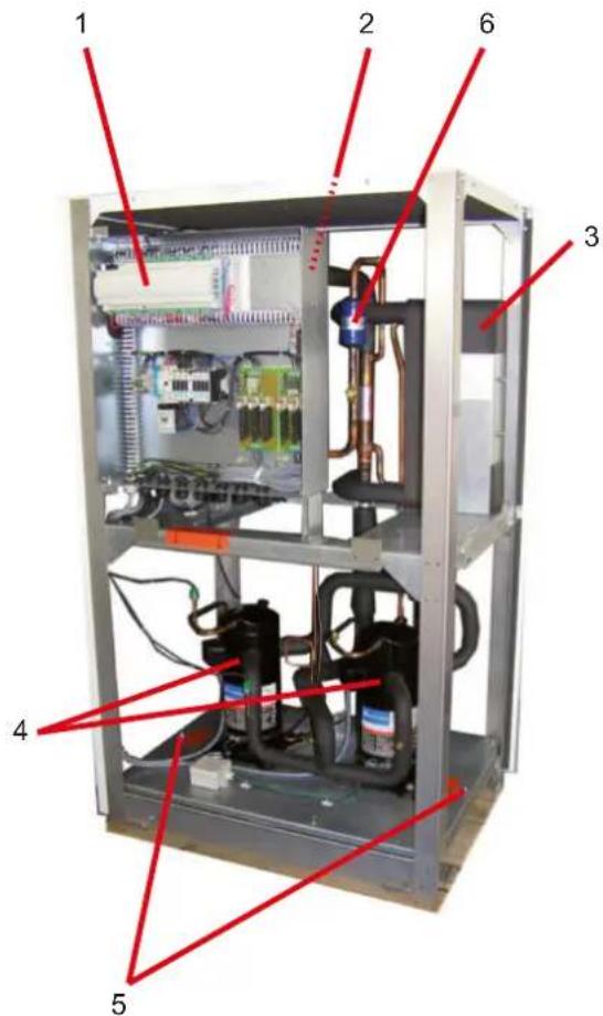
1) Control
2) Evaporator
3) Condenser
4) Compressor
5) Transport securing devices
6) Filter drier
4 Accessories
4.1 Connecting Flanges
The use of flat-sealing connecting flanges allows the unit, as an option, to be connected by means of flanges.
4.2 Remote control
A remote control adds convenience and is available as a special accessory. Operation and menu navigation are identical to those of the heat pump manager. Connection takes place via an interface (special accessories) with RJ 12 Western plug..
NOTE
In the case of heating controllers with a removable operating element, this can also be used directly as a remote control.
4.3 Building management technology
The heat pump manager can be connected to a building management system network via supplementation of the relevant interface plug-in card. The supplementary installation instructions of the interface card must be consulted regarding the exact connection and parameterisation of the interface.
The following network connections can be made on the heat pump manager:
Modbus
EIB, KNX
Ethernet
ATTENTION!
If the heat pump or circulating pumps are controlled externally, an flow rate switch is required to prevent the compressor from being switched on when there is no volume flow.
4.4 Thermal energy meter WMZ
4.4.1 General description
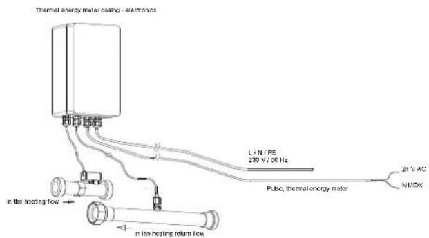
The thermal energy meter (WMZ 25/32) is used for measuring the quantity of thermal energy supplied. It is available as an accessory. Due to the additional heat exchanger, two thermal energy meters are required for measuring the quantity of thermal energy.
Sensors in the flow and return of the heat exchanger pipes and an electronics module acquire the measured values and transmit a signal to the heat pump manager, which, depending on the current operating mode of the heat pump (heating/DHW/swimming pool), totals the thermal energy in kWh and displays them in the operating data and history menu.

NOTE
The thermal energy meter complies with the quality requirements of the German market incentive programme subsidising efficient heat pumps. The thermal energy meter is not subject to obligatory calibration, and can thus not be used for the heating cost billing procedure!
4.4.2 Hydraulic and electrical integration of the thermal energy meter
The thermal energy meter requires two measuring devices for data acquisition.
■ A measuring tube for the flow measurement
This must be installed in the heat pump flow (observe flow direction).
A temperature sensor (copper pipe with immersion sleeve) This must be installed in the heat pump return.
The installation locations for both measuring tubes should be as close to the heat pump as possible in the generator circuit.
The distance from pumps, valves and other installations must be taken into account, as eddying effects could lead to incorrect thermal energy metering (a calming section of 50 cm is recommended).
5 Transport
For the transport by means of a hand truck or boiler trolley, position the latter under the front end of the unit below the transport security device.
For transport on a level surface, the unit can be lifted from the rear or from the front by means of a lift truck or forklift. In this case, the transport securing device is not imperative.

ATTENTION!
The heat pump must not be tilted more than max. 45° (in either direction).
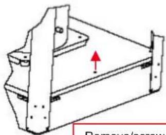
Remove/screw in transport lock
After the transport, the transport securing device is to be removed on either side at the bottom of the unit.

ATTENTION!
The transport securing device is to be removed prior to commissioning.
To remove the panelling, open the individual covers by unscrewing the respective turn-lock fasteners and then gently tilting the covers away from the device. Then lift them up out of the mountings.
6 Installat
6.1 General Information
The brine-to-water heat pump must be installed in a frost-free, dry room on an even, smooth and horizontal surface. The entire frame should lie directly on the floor to ensure an adequate soundproof seal. Failing this, additional sound insulation measures may become necessary.
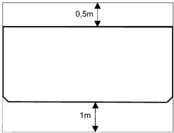
The heat pump should be installed to allow easy maintenance/service access. This is ensured if a clearance of approx. 1 m in front of the heat pump is maintained.
Neither frost nor temperatures higher than 35 °C must occur in the installation location at any time of the year.
6.2 Sound Emissions
The heat pump offers silent operation due to efficient sound insulation. Any vibration transmission to the foundation or the heating system can be largely prevented by internal sound decoupling measures.
7 Mounting
7.1 General Information
The following connections need to be established on the heat pump:
■ Flow and return of the brine (heat source system)
■ supply/return flow of the heating system
■ Temperature sensor
Voltage supply
i7.2 Connection on Heating Side
ATTENTION!
The heating system must be flushed prior to connecting the heat pump.
Before completing the heat pump connections on the heating water side, the heating installation must be flushed in order to remove any impurities that may be present, as well as residues of sealing material, and the like. Any accumulation of deposits in the condenser may result in a total failure of the heat pump.
Once the installation on the heating side has been completed, the heating system must be filled, de-aerated and pressure-tested.
Consideration must be given to the following when filling the system:
■ Untreated filling water and make-up water must be of drinking water quality (colourless, clear, free from sediments)
- Filling water and make-up water must be pre-filtered (pore size max. 5 µm).
Scale formation in domestic hot water heating systems cannot be avoided, but in systems with flow temperatures below 60 °C, the problem can be disregarded. With high-temperature heat pumps and in particular with bivalent systems in the higher performance range (heat pump + boiler combination), flow temperatures of 60 °C and more can be achieved. The following standard values should therefore be adhered to with regard to the filling and make-up water according to VDI 2035, sheet 1: The total hardness values can be found in the table.
| Total heat output in kW | Total alkaline earths in mol/m3 and/or mmol/l | Specific system volume (VDI 2035) in l/kW | ||
| < 20 | ≥ 20 < 50 | ≥ 50 | ||
| Total hardness in °dH | ||||
| < 50 | ≤ 2.0 | ≤ 16.8 | ≤ 11.2 | < 0.11 ^1 |
| 50 - 200 ≤ 2.0 | ≤ 11.2 ≤ 8.4 | |||
| 200 - 600 | ≤ 1.5 | ≤ 8.4 | < 0.11 ^1 | |
| > 600 | < 0.02 | < 0.11 ^1 | ||
- This value lies outside the permissible value for heat exchangers in heat pumps.
Fig. 7.1: Guideline values for filling and make-up water in accordance with VDI 2035
For systems with an above-average specific system volume of 50 l/kW, VDI 2035 recommends using fully demineralized water and a pH stabiliser to minimize the risk of corrosion in the heat pump and the heating system.
ATTENTION!
With fully demineralized water, it is important to ensure that the minimum permissible pH value of 7.5 (minimum permissible value for copper) is complied with. Failure to comply with this value can result in the heat pump being destroyed.
Heating water minimum flow rate
The minimum heating water flow rate through the heat pump must be assured in all operating states of the heating system. This can be accomplished, for example, by installing a dual differential pressureless manifold.
NOTE
The use of an overflow valve is only recommended for panel heating and a max. heating water flow of 1.3 m^3/h . System faults may result if this is not observed.
Provided the heat pump manager and heating circulating pumps are ready for operation, the frost protection feature of the heat pump manager is active. If the heat pump is taken out of service or in the event of a power failure, the system has to be drained. In heat pump installations where a power failure cannot be readily detected (holiday house), the heating circuit must contain a suitable antifreeze product.
7.3 Connection on Heat Source Side
The following procedure must be observed when making the connection:
Connect the brine line to the flow and return pipe heat source of the heat pump.
The hydraulic integration diagram must be observed here.
ATTENTION!
The supplied strainer must be fitted in the heat source inlet of the heat pump in order to protect the evaporator against the ingress of impurities.
The brine liquid must be produced prior to charging the system. The brine concentration must be at least 25 %. Freeze protection down to -14^ can thus be ensured.
Only antifreeze products on the basis of mono-ethylene glycol or propylene glycol may be used.
The heat source system must be vented (de-aerated) and checked for leaks.
ATTENTION!
The brine solution must contain at least 25 % of an antifreeze agent on a mono-ethylene glycol or propylene glycol basis and must be mixed prior to filling.
NOTE
A suitable de-aerator (micro bubble air separator) must be installed in the heat source circuit by the customer.
7.4 Temperature sensor
The following temperature sensors are already installed or must be installed additionally:
■ External temperature sensor (R1) supplied (NTC-2)
■ Return temperature secondary circuit (R2) installed (NTC-10)
■ Flow temperature secondary circuit (R9) installed (NTC-10)
■ Flow temperature primary circuit (R6) installed (NTC-10)
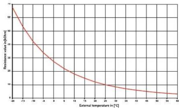
7.4.1 Sensor characteristic curves
| Temperature in °C | -20 | -15 | -10 | -5 | 0 | 5 | 10 | ||
| NTC-2 in kΩ | 14.6 | 11.4 | 8.9 | 7.1 | 5.6 | 4.5 | 3.7 | ||
| NTC-10 In kΩ | 67.7 | 53.4 | 42.3 | 33.9 | 27.3 | 22.1 | 18.0 | ||
| 15 | 20 | 25 | 30 | 35 | 40 | 45 | 50 | 55 | 60 |
| 2.9 | 2.4 | 2.0 | 1.7 | 1.4 | 1.1 | 1.0 | 0.8 | 0.7 | 0.6 |
| 14.9 | 12.1 | 10.0 | 8.4 | 7.0 | 5.9 | 5.0 | 4.2 | 3.6 | 3.1 |
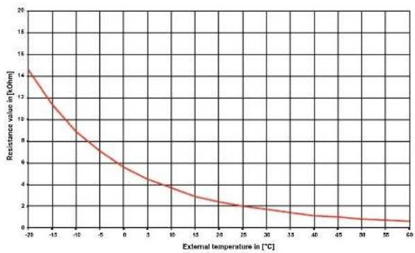
The temperature sensors to be connected to the heat pump manager must correspond to the sensor characteristic curve illustrated in Fig. 7.2. The only exception is the external temperature sensor included in the scope of supply of the heat pump (see Fig. 7.3)
line
| External temperature in [°C] | Resistance value in [kOhm] | | ---------------------------- | --------------------------- | | -20 | 60 | | -15 | 50 | | -10 | 40 | | -5 | 30 | | 0 | 25 | | 5 | 20 | | 10 | 18 | | 15 | 15 | | 20 | 12 | | 25 | 10 | | 30 | 8 | | 35 | 6 | | 40 | 5 | | 45 | 4 | | 50 | 3 | | 55 | 2 | | 60 | 1 |Fig. 7.2: Sensor characteristic curve NTC-10
line
| External temperature in [°C] | Resistance value in [kOhm] | | ---------------------------- | -------------------------- | | -20 | 14 | | -15 | 12 | | -10 | 10 | | -5 | 8 | | 0 | 6 | | 5 | 4 | | 10 | 3 | | 15 | 2.5 | | 20 | 2 | | 25 | 1.5 | | 30 | 1.2 | | 35 | 1 | | 40 | 0.8 | | 45 | 0.6 | | 50 | 0.4 | | 55 | 0.2 | | 60 | 0 |Fig. 7.3: Sensor characteristic curve, NTC-2 according to DIN 44574 External temperature sensor
7.4.2 Mounting the external temperature sensor
The temperature sensor must be mounted in such a way that all weather conditions are taken into consideration and the measured value is not falsified.
■ Mount on the external wall on the north or north-west side where possible
- Do not install in a “sheltered position” (e.g. in a wall niche or under a balcony)
■ Not in the vicinity of windows, doors, exhaust air vents, external lighting or heat pumps
■ Not to be exposed to direct sunlight at any time of year
| Dimensioning parameter sensor lead | |
| Conductor material CuCable-length 50 mAmbient temperature 35 °CLaying systemExternal diameter 4-8 mm | |
| B2 (DIN VDE 0298-4 / IEC 60364-5-52) | |
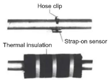
7.4.3 Installing the strap-on sensor
It is only necessary to mount the strap-on sensors if they are included in the scope of supply of the heat pump but have not yet been installed.
The strap-on sensors can be fitted as pipe-mounted sensors or installed in the immersion sleeve of the compact manifold.
Mounting as a pipe-mounted sensor
■ Remove paint, rust and scale from heating pipe.
- Coat the cleaned surface with heat transfer compound (apply sparingly).
- Attach the sensor with a hose clip (tighten firmly, as loose sensors can cause malfunctions) and thermally insulate.
7.4.4 Hydraulic distribution system
The compact manifold and the dual differential pressureless manifold function as an interface between the heat pump, the heating distribution system, the buffer tank and, in some cases, even the hot water cylinder. A compact system is used to simplify the installation process, so that a lot of different components do not have to be installed individually. Further information can be found in the relevant installation instructions.
Compact manifold
The return sensor can remain in the heat pump, or should be installed in the immersion sleeve. The remaining empty space between the sensor and the immersion sleeve must be filled completely with heat transfer compound.
dual differential pressureless manifold
In order for the heating circuit pumps of the generator and consumer circuits to supply the flow to the return sensor, this must be installed in the immersion sleeve of the dual differential pressureless manifold.
7.5 Electrical connection
7.5.1 General
All electrical connection work must be carried out by a trained electrician or a specialist for the specified tasks in accordance with the
■ installation and operating instructions,
■ country-specific installation regulations (e.g. VDE 0100),
■ technical connection conditions of the energy suppliers and supply grid operators (e.g. TAB) and
■ local conditions.
To ensure that the frost protection function of the heat pump works properly, the heat pump manager must remain connected to the power supply and the flow must be maintained through the heat pump at all times.
The switching contacts of the output relay are interference-suppressed. Therefore, depending on the internal resistance of the measuring instrument, a voltage can also be measured when the contacts are open. However, this will be much lower than the line voltage.
Extra-low voltage is connected to controller terminals N1-J1 to N1-J11; N1-J24 to N1-J26 and terminal strip X3; X5. If, due to a wiring error, the line voltage is mistakenly connected to these terminals, the heat pump manager will be destroyed.
7.5.2 Electrical installation
1) The electric supply cable for the output section of the heat pump (up to 4-core) are fed from the electricity meter of the heat pump via the utility blocking contactor (if required) into the heat pump (see the device information for supply voltage).
Connection of the mains cable to the control panel of the heat pump via terminal X1: L1/L2/L3/PE.
ATTENTION!
Ensure the rotary field is clockwise when connecting the mains cables (if the rotary field is not clockwise, the heat pump will not work properly, is very loud and may cause damage to the compressor).
An all-pole disconnecting device with a contact gap of at least 3 mm (e.g. utility blocking contactor or power contactor) and an all-pole circuit breaker with common tripping for all external conductors must be installed in the power supply for the heat pump (tripping current and characteristic in compliance with the device information).
2) The three-core electric supply cable for the heat pump manager (heating controller N1) is fed into the heat pump. Connection of the control line to the control panel of the heat pump via terminal X2: L/N/PE.
The (L/N/PE\~230 V, 50 Hz) supply cable for the heat pump manager must have a constant voltage. For this reason, it should be tapped upstream from the utility blocking contactor or be connected to the household current, as important protection functions could otherwise be lost during a utility block.
3) The utility blocking contactor (K22) with main contacts and an auxiliary contact should be dimensioned according to the heat pump output and must be supplied by the customer.
The NO contact of the utility blocking contactor is looped from terminal strip G/24 V AC to connector terminal J5/ID3. CAUTION! Extra-low voltage!
4) The contactor (K20) for the immersion heater (E10) of mono energy systems (HG2) should be dimensioned according to the radiator output and must be supplied by the customer. It is controlled (230 V AC) by the heat pump manager via terminals N and N1-J13/NO4.
5) The contactor (K21) for the flange heater (E9) in the hot water cylinder should be dimensioned according to the radiator output and must be supplied by the customer. It is controlled (230 V AC) by the heat pump manager via terminals N and N1-J16/NO 10.
6) The contactors mentioned above in points 3, 4 and 5 are installed in the electrical distribution system. Mains cables for the installed heaters must be laid and secured in accordance with the valid standards and regulations.
7) All installed electric cables must have permanent wiring.
8) The heat circulating pump (M13) is connected to N1-J13/NO5 and X2/N. When using pumps where the switching capacity exceeds the output, a coupling relay must be interposed.
9) The auxiliary circulating pump (M16) is connected to N1-J16/NO9 and X2/N. When using pumps where the switching capacity exceeds the output, a coupling relay must be interposed.
10) The domestic hot water circulating pump (M18) is connected to N1-J12/NO6 and X2/N. When using pumps where the switching capacity exceeds the output, a coupling relay must be interposed.
11) The brine or well pump (M11) is activated via the contact N1-J12/NO3. The connection points for the pump are on contactor K5:2/4/6. A coupling relay is already integrated in this output.
12) The return sensor (R2) is integrated into heat pumps for indoor installation.
The heat pump manager is connected via the following terminals: GND and N1-J2/U2.
13) The external sensor (R1) is connected to terminals GND and N1-J2/U1.
14) The domestic hot water sensor (R3) is included with the domestic hot water cylinder and is connected to terminals X3/ GND and N1-J2/U3.
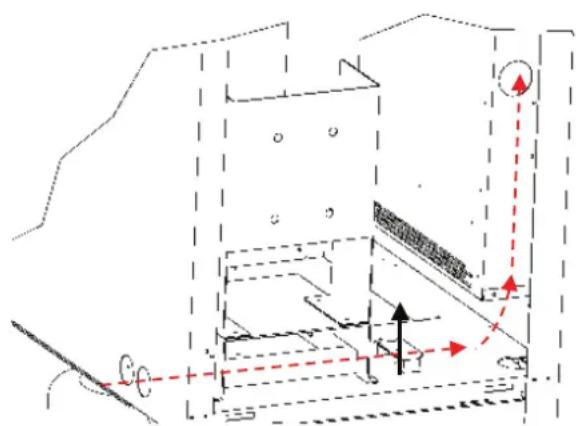
natural_image
Pure technical diagram of a mechanical or architectural component with no visible text, numbers, or symbols.The power cable must be run through the guide tubes, inserted into the side of the control box and secured by means of the strain relief.
7.5.3 Connecting an electronically regulated circulating pump
Electronically regulated circulating pumps have high starting currents, which may shorten the service life of the heat pump manager. For this reason, a coupling relay is installed or must be installed between the output of the heat pump manager and the electronically regulated circulating pump. This is not necessary if the permissible operating current of 2 A and a maximum starting current of 12 A are not exceeded in the electronically regulated circulating pump or if express approval has been issued by the pump manufacturer.

ATTENTION!
It is not permitted to connect more than one electronically regulated circulating pump via a relay output.
8 Commissioning
8.1 General Information
To ensure proper commissioning it should be carried out by a customer service authorised by the manufacturer. These measures can also include an additional warranty under certain conditions (see Warranty).
8.2 Preparatory Steps
Prior to commissioning, the following items need to be checked:
All connections of the heat pump must have been made as described in Chapter 7.
■ The heat source system and the heating circuit must have been filled and checked.
- The strainer must have been fitted in the sole inlet of the heat pump.
In the brine and heating circuits all valves that might impair the proper flow must be open.
The settings of the heat pump controller must be adapted to the heating installation in accordance with the instructions contained in the controller's operating manual.
8.3 Commissioning Procedure
The heat pump is commissioned via the heat pump manager.

ATTENTION!
Start-up must be performed in accordance installation and operating instructions of the heat pump manager..
9 Care/Cleaning
9.1 Care
To prevent malfunctions due to sediments in the heat exchangers, care must be taken that no im-purities can enter the heat source system and the heating installation. In the event that operating malfunctions due to contamination occur nevertheless, the system should be cleaned as described below.
9.2 Cleaning of Heating Side
The ingress of oxygen into the heating water circuit, in particular if it contains steel components, may result in the formation of oxidation products (rust). These can enter the heating system via valves, circulating pumps or plastic tubing. It is therefore important - in particular with respect to the piping of underfloor heating systems - that the installation be executed in a diffusion-proof manner.

ATTENTION!
To prevent the accumulation of deposits (e.g. rust) we recommend using a suitable corrosion protection system.
In the case of severe contamination leading to a reduction in the performance of the condenser in the heat pump, the system must be cleaned by a heating technician.
Based on current information, we recommend using a 5 % phosphoric acid solution for cleaning purposes. However, if cleaning needs to be performed more frequently, a 5 % formic acid solution should be used.
In either case, the cleaning fluid should be at room temperature. It is recommended that the heat exchanger be cleaned in the direction opposite to the normal flow direction.
To prevent acidic cleaning agents from entering the circuit of the heating installation we recommend that the flushing device be fitted directly to the supply and return lines of the condenser of the heat pump.
Thereafter the system must be thoroughly flushed using appropriate neutralising agents in order to prevent any damage caused by cleaning agent residues that may still be present in the system.
All acids must be used with great care, all relevant regulations of the employers' liability insurance associations must be adhered to.
The manufacturer's instructions regarding cleaning agent must be complied with at all times.
9.3 ^th Cleaning of Heat Source Side

ATTENTION!
The supplied strainer must be fitted in the heat source inlet of the heat pump in order to protect the evaporator against the ingress of impurities.
The filter sieve of the dirt trap should be cleaned one day after-start-up. Further checks must be set according to the level of dirt. If no more signs of contamination are evident, the filter can be removed to reduce pressure drops.
10 Malfunctions / Troubleshooting
This heat pump is a quality product and is designed for trouble-free operation. In the event that a malfunction occurs nevertheless, it will be indicated on the display of the heat pump controller. Simply consult the Malfunctions and Troubleshooting table contained in the in-stallation and operating manual of the heat pump controller (manager).
If you cannot correct the malfunction yourself, please contact the after-sales service agent in charge.
11 Decommissioning / Disposal
Before removing the heat pump, disconnect the unit from the power source and close all valves. The heat pump must be installed by trained personnel. Environment-relevant requirements regarding the recovery, recycling and disposal of service fuels and components in accordance with all relevant standards must be adhered to. Particular attention must hereby be paid to the proper disposal of refrigerants and refrigeration oils.
ATTENTION!
All work on the heat pump may only be performed by an authorised an qualified after-sales service.
ATTENTION!
Disconnect all electrical circuits from the power supply before opening the enclosure.
12 Equipment Data
| 1 Type and order code SIH 20TE | |||||
| 2 Design | |||||
| 2.1 Degree of protection according to EN 60 529 IP 21 | |||||
| 2.2 Installation location Indoors | |||||
| 3 Performance data | |||||
| 3.1 Operating temperature limits: | |||||
| Heating water flow °C up to 70 | |||||
| Brine (heat source) °C -5 to +25 | |||||
| Antifreeze Monoethylene glycol | |||||
| Minimum brine concentration (-13 °C freezing temperature) | 25% | ||||
| 3.2 Temperature spread of heating water (flow/return flow)at B0 / W35 K | 9.9 | 5.0 | |||
| 3.3 Heat output / COP | at B-5 / W55 1 | kW / --- | 2 | 18.1 / 2.5 | |
| kW / --- | 3 | 9.1 / 2.5 | |||
| at B0 / W45 1 | kW / --- | 2 | 20.5 / 3.4 | ||
| kW / --- | 3 | 10.5 / 3.4 | |||
| at B0 / W50 1 | kW / --- | 2 | 21.3 / 3.3 | ||
| kW / --- | 3 | 10.5 / 3.2 | |||
| at B0 / W35 1 | kW / --- | 2 | 21.8 / 4.7 | 21.4 / 4.4 | |
| kW / --- | 3 | 11.8 / 4.8 | 11.5 / 4.6 | ||
| 3.4 Sound power level dB(A) 62 | |||||
| 3.5 Sound pressure level at a distance of 1 m dB(A) 47 | |||||
| 3.6 Heating water flow with an internal pressure differential of m3/h / Pa | 1.9 / 2310 | 3.7 / 8500 | |||
| 3.7 Brine throughput with an internal pressure differential (heat source) of m3/h / Pa | 5.1 / 11000 | 4.9 / 10200 | |||
| 3.8 Refrigerant / total filling weight type / kg R134a / 4.2 | |||||
| 3.9 GWP value / CO 2 equivalent --- / t 1430 / 6 | |||||
| 3.10 Refrigeration circuit hermetically sealed yes | |||||
| 3.11 Lubricant / total filling weight type / litres Polyolester (POE) / 3.54 | |||||
| 4 Dimensions, connections and weight | |||||
| 4.1 Device dimensions without connections 4 H x W x L mm 1660 x 1000 x 750 | |||||
| 4.2 Device connections to heating system Inch G 1 1/4" internal/external | |||||
| 4.3 Device connections to heat source Inch G 1 1/2" internal/external | |||||
| 4.4 Weight of the transportable unit(s) incl. packing kg 307 | |||||
| 5 Electrical connection | |||||
| 5.1 Nominal voltage; fuse protection V / A 400 / 25 | |||||
| 5.2 Nominal power consumption 1 B0 W35 kW 4.70 4.86 | |||||
| 5.3 Starting current with soft starter A 30 | |||||
| 5.4 Nominal current B0 W35 / cos φ 2 A / --- 8.48 / 0.8 8.77 / 0.8 | |||||
| 5.5 max. power consumption of compressor protection (per compressor) W 70 | |||||
| 6 Complies with the European safety regulations 5 | |||||
| 7 Additional model features | |||||
| 7.1 Water in device protected against freezing 6 Yes | |||||
| 7.2 Performance levels 2 | |||||
| 7.3 Controller internal/external Internal | |||||
- This data indicates the size and capacity of the system. For an analysis of the economic and energy efficiency of the system, both the bivalence point and the regulation should also be taken into consideration. The specified values, e.g. B10 / W55, have the following meaning: Heat source temperature 10^ and heating water flow temperature 55^ .
- Operation with 2 compressor
- Operation with 1 compressors
- Note that additional space is required for pipe connections, operation and maintenance.
- See CE declaration of conformity
- The heat circulating pump and the heat pump manager must always be ready for operation.
13 Product information as per
Regulation (EU) No 813/
2013, Annex II, Table 2
| Information requirements for heat pump space heaters and heat pump combination heaters | [STX] | Glen Dimplex Thermal Solutions | Dimplex | ||||
| Model | SIH 20TE | ||||||
| Air-to-water heat pump | no | ||||||
| Water-to-water heat pump | no | ||||||
| Brine-to-water heat pump | yes | ||||||
| Low-temperature heat pump | no | ||||||
| Equipped with a supplementary heater | no | ||||||
| Heat pump combination heater | no | ||||||
| Parameters shall be declared for medium-temperature application, except for low-temperature heat pumps. For low- temperature heat pumps, parameters shall be declared for low-temperature application. | |||||||
| Parameters shall be declared for average climate conditions: | |||||||
| Item Symbol Value Unit Item Symbol Value | Unit | ||||||
| Rated heat output (*) | Prated | 20 kW | Seasonal space heating energy efficiency | ηs | 132 | % | |
| Declared capacity for heating foer part load at indoor temperature 20°C and outdoor temperature Tj | Declared coefficient of performance or primary energy ratio for part load at indoor temperature 20 °C and outdoor temperature Tj | ||||||
| Tj = -7°C | Pdh | 20,6 kW | Tj = -7°C | COPd | 2,89 - | ||
| Tj = +2°C | Pdh | 20,9 kW | Tj = +2°C | COPd | 3,45 - | ||
| Tj = +7°C | Pdh | 21,2 kW | Tj = +7°C | COPd | 3,90 - | ||
| Tj = +12°C | Pdh | 21,4 kW | Tj = +12°C | COPd | 4,47 - | ||
| Tj = bivalent temperature | Pdh | 20,4 kW | Tj = bivalent temperature | COPd | 2,75 - | ||
| Tj = operation limit temperature | Pdh | 20,4 kW | Tj = operation limit temperature | COPd | 2,75 - | ||
| For air-to-water heat pumps | For air-to-water heat pumps: | ||||||
| Tj = -15°C (if TOL < -20°C) | Pdh | 20,4 kW | Tj = -15°C (if TOL < -20°C) | COPd | 2,75 - | ||
| Bivalent temperature | Tbiv | -10 °C | For air-to-water heat pumps:Operation limit temperature | TOL -10 °C | |||
| Cycling interval capacity for heating | Pcych | - | kW Cycling interval efficiency | COPcyc | - | - | |
| Degradation co-efficient (**) | Cdh | 0,90 | - | Heating water operating limit temperature | WTOL | 70 | °C |
| Power consumption in modes other than active mode | Supplementary heater | ||||||
| Off mode | POFF | 0,015 | kW Rated | heat output (*) | Psup | 0 | kW |
| Thermostat-off mode | PTO | 0,020 | kW | Type of energy input | eletrical | ||
| Standby mode | PSB | 0,015 | kW | ||||
| Crankcase heater mode | PCK | 0,000 | kW | ||||
| Other items | |||||||
| Capacity control | fixed | For air-to-water heat pumps: Rated air flow rate, outdoors | - | - | m3/h | ||
| Sound power level, indoors/outdoors | LWA | 62/- | dB | For water-/brine-to-water heat pumps: Rated brine or water flow rate, outdoor heat exchanger | - | 4,9 | m3/h |
| Emissions of nitrogen oxides | NOx | - | mg/kWh | ||||
| For heat pump combination heater: | |||||||
| Declared load profile | - | Water heating energy efficiency | ηwh | - | % | ||
| Daily electricity consumption | Qelec | - | kWh | Daily fuel consumption | Qfuel | - | kWh |
| Contact details | Glen Dimplex Deutschland GmbH, Am Goldenen Feld 18, 95326 Kulmbach | ||||||
| (*) For heat pump space heaters and heat pump combination heaters, the rated output Prated is equal to the design load for heating Pdesignh, and the rated heat output of a supplementary capacity for heating sup(Tj). | |||||||
| (**) If Cdh is not determined by measurement nthen the default degradation is Cdh = 0,9(-) not applicable | |||||||
Table des matières
1 A lire immediatement....FR-2
natural_image
Technical line drawing of a door frame with 45-degree angle标注 (no text or symbols beyond measurement)ATTENTION!
Heating water return
Heating water supply
Heat source
Heat source
Heat pump inlet
Heat pump inlet
Heat pump inlet 1 14 " external thread
line
| Wärmequelleneintrittstemperatur [°C] | Heizwassertemperatur [°C] / Heating water temperature [°C] | | ------------------------------------ | -------------------------------------------------------- | | 0 | 20 | | 1 | 65 | | 2 | 70 | | 3 | 70 | | 4 | 70 | | 5 | 70 | | 6 | 70 | | 7 | 70 | | 8 | 70 | | 9 | 70 | | 10 | 70 | | 11 | 70 | | 12 | 70 | | 13 | 70 | | 14 | 70 | | 15 | 70 | | 16 | 70 | | 17 | 70 | | 18 | 70 | | 19 | 70 | | 20 | 70 | | 21 | 70 | | 22 | 70 | | 23 | 70 | | 24 | 70 | | 25 | 70 | | 26 | 70 | | 27 | 70 | | 28 | 70 | | 29 | 70 | | 30 | 70 | | 31 | 70 | | 32 | 70 | | 33 | 70 | | 34 | 70 | | 35 | 70 | | 36 | 70 | | 37 | 70 | | 38 | 70 | | 39 | 70 | | 40 | 70 | | 41 | 70 | | 42 | 70 | | 43 | 70 | | 44 | 70 | | 45 | 70 | | 46 | 70 | | 47 | 70 | | 48 | 70 | | 49 | 70 | | 50 | 70 | | 51 | 70 | | 52 | 70 | | 53 | 70 | | 54 | 70 | | 55 | 70 | | 56 | 70 | | 57 | 70 | | 58 | 70 | | 59 | 70 | | 60 | 70 | | Note: The actual values for the heating water temperature are not provided in the code. The actual values for the heating water temperature are calculated based on the formula 'Temperature d' entered in the source of the chaleur. There is no label data provided in the code. The values are estimated based on the formula 'Heizwassertemperatur [°C] / Heating water temperature [°C]' and are not explicitly shown in the code. The labels in the chart include 'Wasseraustritt (+/-2 K)' and 'Water outlet (+/-2 K)'.3 Stromlaufpläne / Wiring diagrams / Schémas électriques
flowchart
graph TD
    subgraph Power Source
        X2["PE"] --> X2/N
        X1["PE"] --> X14
        X14 --> T1["T1"]
        X14 --> J10["J10"]
        J10 --> J11["J11"]
        J11 --> J12["J12"]
        J12 --> J13["J13"]
        J13 --> J25BMS2["J25 BMS2"]
        J25BMS2 --> J26FBus2["J26 FBus2"]
        J26FBus2 --> J14["J14"]
        J14 --> J6["J6"]
        J6 --> ID9["ID9"]
        ID9 --> J7["J7"]
        J7 --> ID13H["ID13H"]
        ID13H --> ID8ID14["H8"]
    end

    subgraph Control
        X2/PE --> X2/N
        X2/PE --> X2/N
        X2/PE --> X2/PE
        X2/PE --> X2/PE
        X2/PE --> X2/PE
        X2/PE --> X2/N
        X2/PE --> X2/N
        X2/PE --> X2/N
    end

    subgraph Power Supply
        X14["PE L3 L2 L1"] --> X14
        X14 --> T4A["T4A"]
        T4A --> F2["F2"]
        F2 --> X2/PE
        X2/PE --> X2/PE
        X2/PE --> X2/PE
    end

    subgraph Control
        X14["PE L3 L2 L1"] --> X14
        X14 --> T4A["T4A"]
        T4A --> F2
    end

    subgraph Power Supply
        X14["PE L3 L2 L1"] --> X14
        X14 --> T4A["T4A"]
        T4A --> F2
    end

    subgraph Control
        X14["PE L3 L2 L1"] --> X14
        X14 --> T4A["T4A"]
        T4A --> F2
    end

    subgraph Power Supply
        X14["PE L3 L2 L1"] --> X14
        X14 --> T4A["T4A"]
        T4A --> F2
    end

    subarray
    subgraph Control
    direction TB
    direction LR
    subgraph Power Supply
    direction LR
    direction F2
    subgraph Control
    direction F2
    subgraph Power Supply
    direction F2
    subgraph Control
    direction F2
    subgraph Power Supply
    direction F2
    subgraph Control
    direction F2
    subgraph Control
    direction F2
    subgraph Power Supply
    direction F2
    end

    subgraph Control
    direction F2
    direction F2
    subgraph Power Supply
    direction F2
    subgraph Control
    direction F2
    subgraph Control
    direction F2
    subgraph Power Supply
    direction F2
    end

    subgraph Control
    direction F2
    direction F2
    subgraph Power Supply
    direction F2
    subgraph Control
    direction F2
    subgraph Control
    direction F2
    subarray_text<|ref_end|><|rotate_up|>
    end

    subgraph Control
    direction LR
    direction F2
    direction F2
    direction F2
    direction F2
    direction F2
    direction F2
    direction F2
    direction F2
    direction F2
    direction F2
    direction F2
    direction F2
    direction F2
    direction F2
    direction F2

    subgraph Control
    direction LR
    direction F2
    direction F2
    direction F2
    direction F2
    direction F2
    direction F2
    direction F2

    subgraph Control
    direction LR
    direction F2
    direction F2
    direction F2
    direction F2

    subgraph Power Supply
    direction LR
    direction F2
    direction F2
    direction F2

    subgraph Control
    direction LR
    direction F2
    direction F2

    subgraph Control
    direction LR
    direction F2

    subgraph Power Supply
    direction LR
    direction F2

    end

    subgraph Control
    direction LR
    direction F2

    subgraph Power Supply
    direction LR
    direction F2

    end
3.4 Legende / Legend / Légende
| A1 Drahtbrücke einlegen wenn kein EVU-Sperrschütz benötigt wird (Eingang offen = EVU-Sperre = Wärmepumpe „aus“) | Insert wire jumper if the utility blocking contactor is not required (input open = utility block = heat pump "off"). | Pont à insérer en absence d'un contacteur de blocage EJP (entrée ouverte = blocage EJP = pompe à chaleu "arrêtée") | |
| A2 | Drahtbrücke bei Nutzung des 2ten Sperreinganges entfernen (Eingang offen = Wärmepumpe „aus“) | Remove the wire jumper if the utility blocking contactor is used (input open = heat pump "off"). | Pont à retirer si la 2ème entrée du contacteur de blocage est utilisée (entrée ouverte = pompe à chaleur "arrêtée") |
| A4 Drahtbrücke Störung Verdichter; wird bei Verwendung eines Störungskontaktes ersetzt | Wire jumper compressor fault; replaced if a fault contactor is used. | Pont défaut compresseur à retirer en cas d'utilisation d'un contact de défaut | |
| B2* | Pressostat Niederdruck-Sole | Pressostat low pressure, brine | Pressostat basse pression eau glycolée |
| B3* Thermostat Warmwasser Thermostat, hot water Thermostat eau chaude | |||
| B4* | Thermostat Schwimmbadwasser | Swimming pool water thermostat | Thermostat eau de piscine |
| E1 Ölsumpfheizung M1 Oil sump heater for M1 Chauffage à carter d'huile M1 | |||
| E2 | Ölsumpfheizung M3 | Oil sump heater for M3 | Chauffage à carter d'huile M3 |
| E9* | Flanschheizung Warmwasser | Flange heater domestic hot water | Cartouche chauffante eau chaude sanitaire |
| E10* | 2. Wärmeerzeuger (Funktion über Regler wählbar) | Heat generator 2 (selectable via controller) | 2e générateur de chaleur (réglable par le régulateur) |
| F2 Lastsicherung für N1-Relaisausgänge an J12 und J13 4,0 ATr | Load fuse for N1 relay outputs across J12 and J13 4,0 A slow-acting | Coupe-circuit de la charge pour sorties de relais en J12 et J13 4,0 ATr | |
| F3 | Lastsicherung für N1-Relaisausgänge an J15 bis J18 4,0 AT | Load fuse for N1 relay outputs across J15 to J18 4,0 A slow-acting | Coupe-circuit de la charge pour sorties de relais en J15 jusqu'à J18 4,0 ATr |
| F4 | Pressostat Hochdruck | Pressostat, high pressure | Pressostat haute pression |
| F5 | Pressostat Niederdruck | Pressostat, low pressure | Pressostat basse pression |
| F10.1 | Durchflussschalter Primärkreis | Flow rate switch for primary circuit | Commutateur de débit circuit primaire |
| F10.2* | Durchflussschalter Sekundärkreis | Flow rate switch for secondary circuit | Commutateur de débit circuit secondaire |
| H5* | Leuchte Störfernanzeige | Lamp, remote fault indicator | Lampe témion télédétection des pannes |
| J1 | Spannungsversorgung-N1 (24VAC) | Voltage supply N1 (24 V AC) | Alimentation en tension N1 (24 V AC) |
| J2 - J3 | Analogeingänge | Analogue inputs | Entrées analogiques |
| J4 | Analogausgänge | Analogue outputs | Sorties analogiques |
| J5 | Digitaleingänge | Digital inputs | Entrées numériques |
| J6 | Analogausgänge | Analogue outputs | Sorties analogiques |
| J7 - J8 | Digitaleingänge | Digital inputs | Entrées numériques |
| J10 Bedienteil | Control panel | Unité de commande | |
| J11 | frei | free | libre |
| J12 - J18 230 V AC - Ausgänge | 230 V AC - outputs | Sorties 230 V AC pour | |
| J24 | Spannungsversorgung für Komponenten | Power supply for components | Alimentation en tension des composants |
| J25 Schnittstelle | Interface | Interface | |
| J26 | Schnittstelle | Interface | Interface |
| K1 Schütz M1 | Contactor M1 | Contacteur M1 | |
| K3 | Schütz M3 | Contactor M3 | Contacteur M3 |
| K5 Schütz M11 | Contactor M11 | Contacteur M11 | |
| K20* | Schütz 2. Wärmeerzeuger E10 | Contactor, suppl. heating system E10 | Contacteur 2ème générateur de chaleur E10 |
| K21* | Schütz Flanschheizung E9 | Flange heater contactor E9 | Contacteur cartouche chauffante E9 |
| K22* | EVU-Sperrschütz | Utility company disable contactor | Contacteur EDF |
| K23* | Hilfsrelais für Sperreingang | Auxiliary relay for disable contactor | Relais auxiliaire pour entrée du contacteur de blocage |
| M1 | Verdichter 1 | Compressor 1 | Compresseur 1 |
| M3 | Verdichter 2 | Compressor 2 | Compresseur 2 |
| M11* | Primärkreispumpe | Primary circuit pump | Pompe circuit primaire |
| M13* | Heizungsumwälzpumpe Hauptkreis | Heat circulating pump of the main circuit | Circulateur de chauffage circuit principal |
| M15* | Heizungsumwälzpumpe 2. Heizkreis | Heating circulating pump for heating circuit 2 | Circulateur de chauffage 2ème circuit de chauffage |
| M16* | Zusatzumwälzpumpe | Suppl. circulating pump | Circulateur d'appoint |
| M18* | Warmwasserladepumpe | Hot water loading pump | Pompe de charge eau chaude sanitaire |
| M21* | Mischer Hauptkreis | Mixer, principal circuit | Mélangeur circuit principal |
| M22* | Mischer 2. Heizkreis | Mixer, heating circuit 2 | Mélangeur 2ème circuit de chauffage |
| N1 | Wärme pumpenmanager | Heat pump manager | Gestionnaire de pompe à chaleur |
| N7 | Sanftanlaufsteuerung M1 | Soft start control M1 | Commande de démarrage progressif M1 |
| N8 | Sanftanlaufsteuerung M3 | Soft start control M3 | Commande de démarrage progressif M3 |
| N14 | Bedienteil | Operating element | Commande |
| N17* | pCOe- Modul | pCOe module | Module pCOe |
| N20* | Wärmemengenzähler | Thermal energy meter | Compteur de chaleur |
| Q1 | Motorschutzschalter M11 | Protective motor switch M11 | Disjoncteur de protection moteur M11 |
| R1* | Außenfühler | External sensor | Sonde extérieure |
| R2 | Rücklauffühler Sekundärkreis | Return sensor, secondary circuit | Sonde retour circuit secondaire |
| R3* | Warmwasserfühler (alternativ zum Warmwasserthermostat) | Hot water sensor (as an alternative to hot water thermostat) | Sonde eau chaude (alternative au thermostat eau chaude) |
| R5* | Fühler für 2. Heizkreis | Sensor for heating circuit 2 | Sonde pour 2ème circuit de chauffage |
| R6 | Vorlauffühler Primärkreis | Flow sensor, primary circuit | Sonde départ circuit primaire |
| R7 | Kodierwiderstand | Coding resistor | Résistance avec code des couleurs |
| R9 | Vorlauffühler Sekundärkreis | Flow sensor, secondary circuit | Sonde départ circuit secondaire |
| R13* | Fühler regenerativ, Raumfühler, Fühler 3. Heizkreis | Renewable sensor, room sensor, sensor for heating circuit 3 | Sonde mode régénératif, sonde d'ambiance, sonde 3ème circuit de chauffage |
| T1 | Sicherheitstrenntransformator 230/24 50Hz / 28VA | Safety isolating transformer 230/24 50Hz / 28VA | Transformateur de coupure de sécurité 230/24 50Hz / 28VA |
| X1 Klemmenleiste: Einspeisung Last 3-/PE 400VAC ~50Hz | Terminal strip: Load infeed 3-/PE 400VAC ~50Hz | Bornier : alimentation en puissance 3-/PE 400 V AC ~50 Hz | |
| X2 | Klemmenleiste: Einspeisung Steuerspannung 1-/N/PE 230VAC ~50Hz | Terminal strip: Control voltage infeed 1-/ N/PE 230VAC ~50Hz | Bornier : alimentation en tension de commande 1-/ N/PE 230 V AC ~50 Hz |
| X3 | Klemmenleiste Kleinspannung | Terminal strip: extra-low voltage | Bornier : tension de sécurité |
| X5 | Busklemme | Bus terminal | Borne de bus |
| X6 | Klemmleiste Ölsumpfheizung | Oil sump heater terminal strip | Bornier chauffage à carter d'huile |
| Y1 | Vier-Wege-Umschaltventil | Four-way reversing valve | Vanne d'inversion 4 voies |
| * | Bauteile sind bauseits beizustellen | Components must be supplied by the customer | Composants à fournir par le client |
| ---- | werksseitig verdrahtet | Wired ready for use | câblé départ usine |
| ---- | bauseits bei Bedarf anzuschließen | To be connected by the customer as required | à raccorder par le client au besoin |
flowchart
graph TD
    A["Source"] --> B["Main Circuit"]
    B --> C["Resistor (R1), Resistor (R2), Resistor (R3), Resistor (R4), Resistor (R5), Resistor (R6), Resistor (R7), Resistor (R8), Resistor (R9), Resistor (R10)"]
    C --> D["Resistor (M11), Resistor (M12), Resistor (M13), Resistor (M14), Resistor (M15), Resistor (M16), Resistor (M17), Resistor (M18), Resistor (M19), Resistor (M20)"]
    D --> E["Resistor (M21, M22, M23)"]
    E --> F["Resistor (M24, M25, M26)"]
    F --> G["Resistor (M27, M28, M29)"]
    G --> H["Resistor (M30, M31, M32)"]
    H --> I["Resistor (M33, M34, M35)"]
    I --> J["Resistor (M36, M37, M38)"]
    J --> K["Resistor (M39, M40, M41)"]
    K --> L["Resistor (M42, M43, M44)"]
    L --> M["Resistor (M45, M46, M47)"]
    M --> N["Resistor (M48, M49, M50)"]
    N --> O["Resistor (M51, M52, M53)"]
    O --> P["Resistor (M54, M55, M56)"]
    P --> Q["Resistor (M57, M58, M59)"]
    Q --> R["Resistor (M60, M61, M62)"]
    R --> S["Resistor (M63, M64, M65)"]
    S --> T["Resistor (M66, M67, M68)"]
    T --> U["Resistor (M69, M70, M71)"]
    U --> V["Resistor (M72, M73, M74)"]
    V --> W["Resistor (M75, M76, M77)"]
    W --> X["Resistor (M78, M79, M80)"]
    X --> Y["Resistor (M81, M82, M83)"]
    Y --> Z["Resistor (M84, M85, M86)"]
    Z --> AA["Resistor (M87, M88, M89)"]
    AA --> AB["Resistor (M90, M91, M92)"]
    AB --> AC["Resistor (M93, M94, M95)"]
    AC --> AD["Resistor (M96, M97, M98)"]
    AD --> AE["Resistor (M99, M100)"]
    AE --> AF["Output"]

    subgraph Power Supply
        direction TB
        direction LR
        direction CV
        direction DV
        direction DW
        direction DV
        direction CV
        direction DV
        direction DV
        direction DV
        direction DV
        direction DV
        direction DV
        direction DV
        direction DV
        direction DV
        direction DV
        direction DV
        direction DV
        direction DV
        direction DV
        direction DV
        direction DV
        direction DV
        direction DV
        direction DV
        direction DV
        direction DV
        direction DV
        direction DV
        direction DV
        direction DV
        direction GV
        direction GV
        direction GV
        direction GV
        direction GV
        direction GV
        direction GV
        direction GV
        direction GV
        direction GV
        direction GV
        direction GV
        direction GV
        direction GV
        direction GV
        direction GV
        direction GV
        direction GV
        direction GV
        direction GV
        direction GV
        direction GV
        direction GV
        direction GV
        direction GV
        direction SV
        direction SV
        direction SV
        direction SV
        direction SV
        direction SV
        direction SV
        direction SV
        direction SV
        direction SV
        direction SV
    end
4.2 Legende / Legend / Légende
You can find and download the current CE conformity declaration at:


- Installation and Operating Instruction
- ACHTUNG!
- Glen Dimplex Thermal Solutions
- Table of contents
- Read immediately....EN-2
- Purpose of the heat pump ......EN-3
- Baseline Unit......EN-4
- Accessories......EN-4
- Transport......EN-5
- Installation....EN-6
- Mounting......EN-6
- Commissioning......EN-10
- Care/Cleaning......EN-10
- Malfunctions / Troubleshooting......EN-11
- Decommissioning / Disposal......EN-11
- Equipment Data......EN-12
- Product information as per Regulation (EU) No 813/2013, Annex II, Table 2...... EN-13
- Anhang / Appendix / Annexes ...... A-I
- Read immediately
- Important Information
- ATTENTION!
- Intended Use
- Legal Provisions and Guidelines
- Energy-Efficient Use of the Heat Pump
- Purpose of the heat pump
- Application
- Principle of Operation
- Baseline Unit
- Accessories
- Connecting Flanges
- Remote control
- NOTE
- Building management technology
- Thermal energy meter WMZ
- General description
- Hydraulic and electrical integration of the thermal energy meter
- Transport
- Installat
- General Information
- Sound Emissions
- Mounting
- General Information
- i7.2 Connection on Heating Side
- Heating water minimum flow rate
- Connection on Heat Source Side
- Temperature sensor
- Sensor characteristic curves
- Mounting the external temperature sensor
- Installing the strap-on sensor
- Mounting as a pipe-mounted sensor
- Hydraulic distribution system
- Compact manifold
- dual differential pressureless manifold
- Electrical connection
- General
- Electrical installation
- Connecting an electronically regulated circulating pump
- Commissioning
- General Information
- Preparatory Steps
- Commissioning Procedure
- Care/Cleaning
- Care
- Cleaning of Heating Side
- th Cleaning of Heat Source Side
- Malfunctions / Troubleshooting
- Decommissioning / Disposal
- Equipment Data
- Product information as per
- Regulation (EU) No 813/
- 2013, Annex II, Table 2
- Table des matières
- A lire immediatement....FR-2
- Heating water return
- Heating water supply
- Heat source
- Heat pump inlet
- Heat pump inlet 1 14 " external thread
- Stromlaufpläne / Wiring diagrams / Schémas électriques
- Legende / Legend / Légende
Brand : DIMPLEX
Model : SIH 20TE
Category : Water pump