
37XRA - Multimeter Amprobe - Free user manual and instructions
Find the device manual for free 37XRA Amprobe in PDF.
| Product Type | Digital Multimeter |
| Brand | Amprobe |
| Model | 37XRA |
| Dimensions (H × W × D) | 196 mm × 92 mm × 60 mm |
| Weight (with battery and case) | 482 g |
| Power Supply | 9 V battery (NEDA 1604, JIS 006P, IEC 6F22) |
| Display | 4-digit LCD (9999 counts) + 41-segment analog bargraph |
| Main Functions | DC/AC voltage (true RMS), DC/AC current (true RMS), resistance, capacitance, inductance, frequency, duty cycle, diode test, continuity, TTL/CMOS logic test, dBm |
| Advanced Functions | MIN/MAX/AVG, Peak Hold, HOLD, Relative (REL), backlight, auto/manual ranging |
| Safety Category | CAT III 600 V, CAT II 1000 V |
| Certifications | EN61010-1, EN61010-2-033, UL61010-1, EN61326-1 (EMC), CE |
| Input Protection | Fast-acting fuse 0.5 A/1000 V (mA) and 10 A/1000 V (10 A) |
| Auto Power Off | Approximately 30 minutes (disabling possible) |
| Maintenance and Cleaning | Clean with a soft cloth dampened with water; do not use solvents |
| Spare Parts Available | Fuse 0.5 A/1000 V (FP300/FP500), fuse 10 A/1000 V (FP100), test lead set TL36, Magne-Grip® case XR-H2 |
| Warranty | 3 years |
| Package Contents | Multimeter, test leads with alligator clips, Magne-Grip® case with magnet clip and strap, type K thermocouple, 9 V battery installed, spare mA fuse, user manual |
Frequently Asked Questions - 37XRA Amprobe
User questions about 37XRA Amprobe
0 question about this device. Answer the ones you know or ask your own.
Ask a new question about this device
Download the instructions for your Multimeter in PDF format for free! Find your manual 37XRA - Amprobe and take your electronic device back in hand. On this page are published all the documents necessary for the use of your device. 37XRA by Amprobe.
USER MANUAL 37XRA Amprobe
Professional Digital Multimeter
True RMS with Component and Logic Test
Users Manual
Mode d'emploi
Bedienungshandbuch
- Manuale d'Uso
- Manual de uso
- RykoBoDCTBO NOIb3OBaTeJIa
AMPROBE
37XR-A Professional Digital Multimeter
Users Manual
Mode d'emploi
Bedienungshandbuch
- Manuale d'Uso
- Manual de uso
Contents
Safety Information 2
Symbols Used in this Manual 2
Introduction. 3
Making Measurements 3
Verify Instrument Operation 3
Range Selection 3
Correcting an Overload OL or Indication 3
Measuring DC Voltage .See Figure -1. 4
Measuring AC Voltage (True rms).See Figure -2- & -3- 4
Preparing for Current Measurements 4
Measuring DC Current.... See Figure 4.
Measuring AC Current (True rms). See Figure -3- & -5- 4
Measuring Resistance. See Figure 6 5
Testing for Continuity . See Figure -7 5
Testing Diodes. See Figure -8 5
Measuring Capacitance. See Figure -9 5
Measuring Inductance....See Figure -10- 6
Measuring Frequency. See Figure -11
Measuring Dutycycle. See Figure -12 6
Measuring dBm. See Figure -13- 6
Testing Logic Levels. See Figure -14 6
Additional Features. 7
Input Test Lead Warning 7
True-rms Measurements 7
MIN MAX AVG Measurements. 7
Peak Hold Measurements 7
Beeper Off. 8
Auto Power Off 8
REL (Relative) Measurements 8
HOLD Measurements. 8
Backlight 8
Product Maintenance. 9
Battery and Fuse Replacement. See Figure -15
Repair 9
WARRANTY 10
Specifications 11
Manual Supplement 37XR-A Users


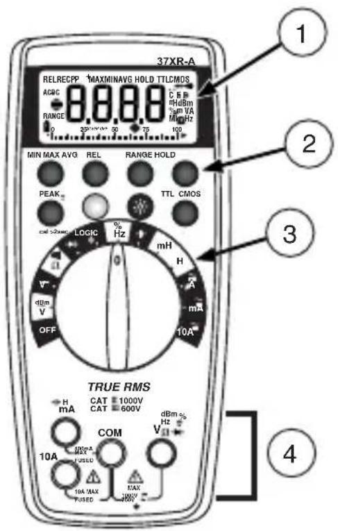
1. Display
Afficheur
Anzeige
Display
Pantalla
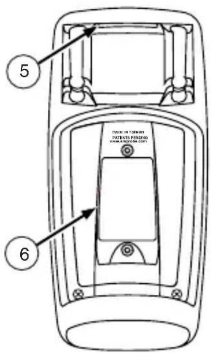
5. Strap Clip
Clip de bretelle
Klemme
Clip in velcro
Clip para correa
2. Feature Buttons
6. Battery/Fuse Cover
3. Function/Range Switch
4. Test Lead Connections
- The 37XR-A Digital Multimeter is UL, CSA, and EN61010-1 certified for Installation Category III - 600V and Category II - 1000V. It is recommended for use with local level power distribution, appliances, portable equipment, etc, where only smaller transient overvoltages may occur, and not for primary supply lines, overhead lines and cable systems.
CAT II: Is for measurements performed on circuits directly connected to the low-voltage installation.
CAT III: Is for measurements performed in the building installation.
- Do not exceed the maximum overload limits per function (see specifications) nor the limits marked on the instrument itself. Never apply more than 1000V dc/750 V ac rms between the test lead and earth ground.
- Inspect the DMM, test leads and accessories before every use. Do not use any damaged part.
- Never ground yourself when taking measurements. Do not touch exposed circuit elements or test probe tips.
- Do not operate the instrument in an explosive atmosphere.
- Exercise extreme caution when: measuring voltage >20V // current >10mA // AC power line with inductive loads // AC power line during electrical storms // current, when the fuse blows in a circuit with open circuit voltage >1000V // servicing CRT equipment.
- Always measure current in series with the load - NEVER ACROSS a voltage source. Check fuse first. Never replace a fuse with one of a different rating.
- Do not change the position of the Function/Range Switch while the MIN MAX, feature is enabled. Erroneous readings will result.
- Remove test leads before opening the Battery Cover or case.
Symbols Used in this Manual
| 1 | Battery Refer to the manual | Δ | |
| 2 | Double insulated Dangerous Voltage | Δ | |
| 3 | Direct Current Earth Ground | ↓ | |
| ~ | Alternating Current Audible tone | ··· | |
| ⇔ | Fuse Underwriters Laboratories, Inc. | ···· | |
| CE | Complies with EU directives | ||
Introduction
The 37XR-A is a true rms autoranging handheld digital multimeter for measuring or testing the following:
DC and AC voltage
- Capacitance
DC and AC current
Diodes
- Resistance
Continuity
Inductance
- dBm
Frequency
-
Logic Levels, TTL or CMOS
-
Dutycycle
Additional features include: MIN MAX AVG, HOLD, REL, PEAK±, Backlight, and Range Lock
Making Measurements
Verify Instrument Operation
Before attempting to make a measurement, verify that the instrument is operational and the battery is good. If the instrument is not operational, have it repaired before attempting to make a measurement.
Range Selection
In addition to autoranging the 37XR-A allows you to manually select and lock a range by pressing the RANGE button. RANGE appears on the display to indicate that manual ranging is active. Each subsequent press of the range button steps the meter to the next higher range. When the highest range is reached the next press returns the meter to the lowest range. To return to autoranging press and hold the RANGE button for 2 seconds. RANGE no longer shows on the display.
Use autorange for all initial measurements. Then, when appropriate, use the RANGE button to select and lock a range.
Warning To avoid electrical shock while manual ranging use the display annunciators to identify the actual range selected.
Correcting an Overload (Oor) - medication

An indication may appear on the display to indicate that an overload condition exists. For voltage and current measurements, an overload should be immediately corrected by selecting a higher range. If the highest range setting does not eliminate the overload, interrupt the measurement until the problem is identified and eliminated. The indication is normal for some functions; for example, resistance, continuity, and diode test.
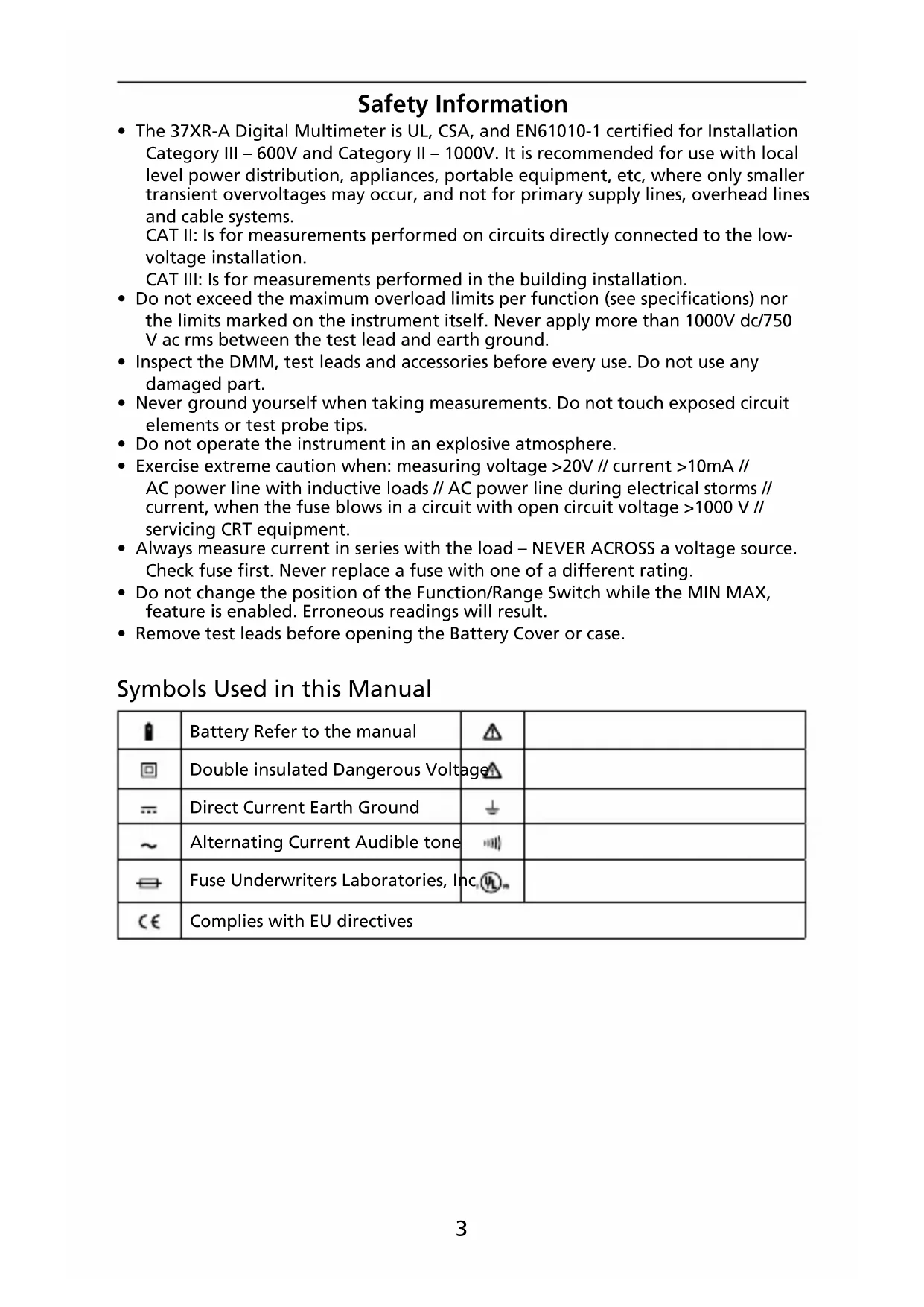
Measuring DC Voltage See Figure
- Set the Function Switch to V
- If RANGE is displayed, press the RANGE button to enable autoranging.
- Connect the Test Leads: Red to Black to COM
- Connect the Test Probes to the circuit test points.
- Read the display, and, if necessary, correct any overload (OL) conditions.
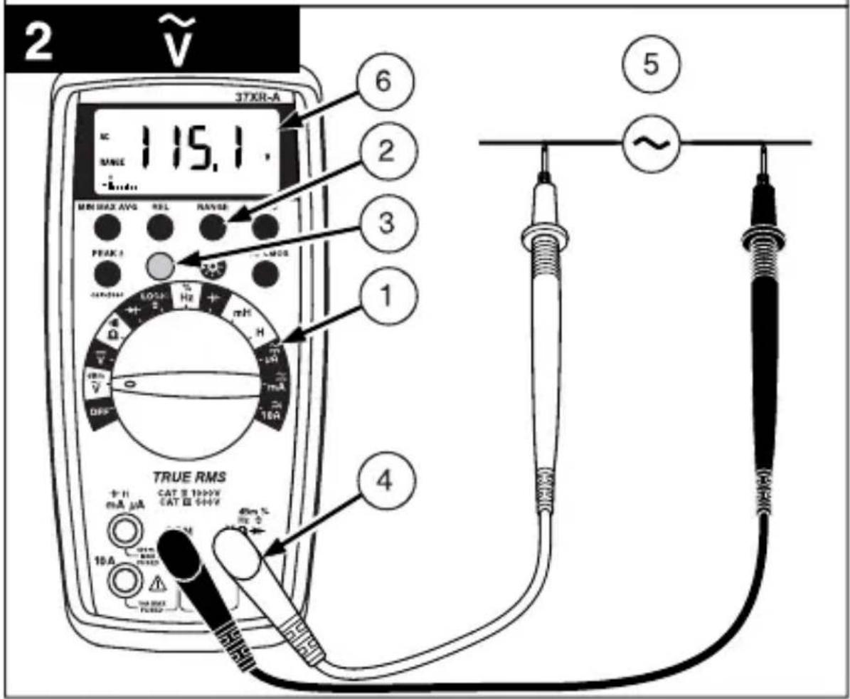
Measuring AC Voltage (True rms)
See Figure -2- & -3-
See Additional Features to find out the advantages of true rms.
- Set the Function Switch to .
- If RANGE is displayed, press the RANGE button to enable autoranging.
- If dBm is displayed, press the yellow button to turn off dBm (enable
- Connect the Test Leads: Red to V + Black toCOM
- Connect the Test Probes to the circuit test points.
- Read the display, and, if necessary, correct any overload ( conditions.
Preparing for Current Measurements
- Turn off circuit power before connecting the test probes.
- Allow the meter to cool between measurements if current measurements approach or exceeds 10 amps.
- A warning tone sounds if you connect a test lead to a current input before you select a current function.
- Open circuit voltage at the measurement point must not exceed 1000V .
- Always measure current in series with the load. Never measure current across a voltage source.
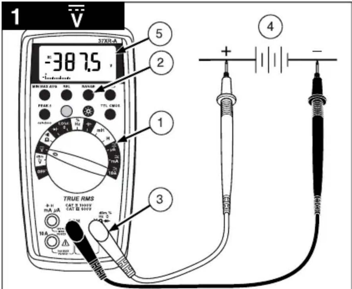
Measuring DC Current See Figure
- Set the Function Switch to a current function, A , mA , or 10A.
- If the 10A function is not selected and RANGE is displayed, press the RANGE button to enable autoranging.
- Connect the Test Leads: Red to A mA or 10A, Black to COM
- Turn off power to the circuit being measured.
- Open the test circuit () to establish measurement points.
- Connect the Test Probes in series with the load.
- Turn on power to the circuit being measured.
- Read the display, and, if necessary, correct any overload (Obr) conditions.
Measuring AC Current (True rms)
See Figure -3- & -5-
See Additional Features to find out the advantages of true rms.
- Set the Function Switch to a current function and range, A,mA ,or 10A.
- If DC is displayed, press the yellow button to turn on AC.
- If the A or mA function is not selected and RANGE is displayed, press the RANGEButton to enable autoranging.
- Connect the Test Leads: Red to A mA or 10A, Black to COM
-
Turn off power to the circuit being measured.
-
Open the test circuit ( ) to establish measurement points.
- Connect the Test Probes in series with the load.
- Turn on power to the circuit being measured.
- Read the display, and, if necessary, correct any overload conditions.
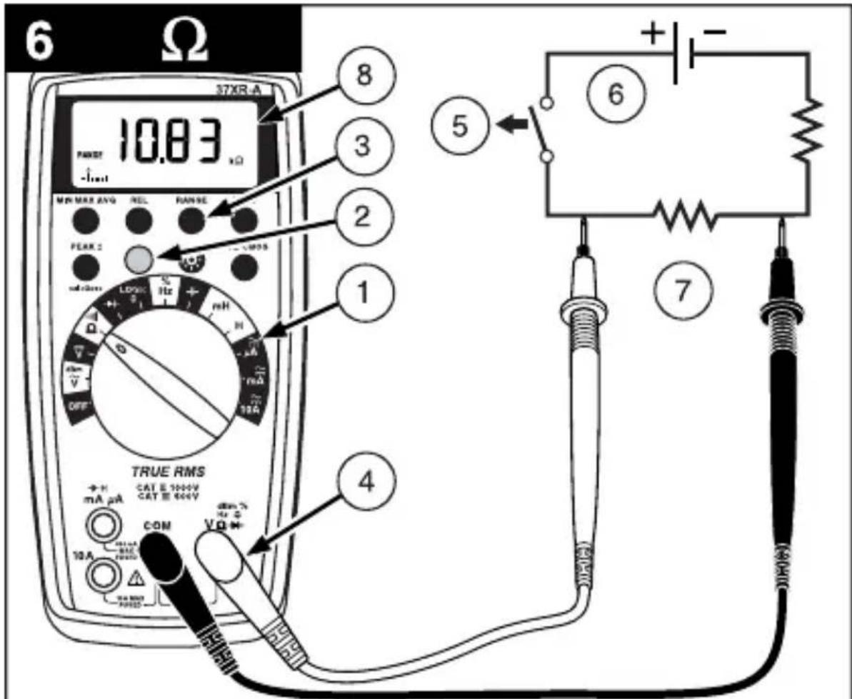
Measuring Resistance See Figure
- Set the Function Switch to
- If is displayed, press the yellow button to display
- If RANGE is displayed, press the RANGE button to enable autoranging.
- Connect the Test Leads: Red to Black to COM
- Turn off power to the circuit being measured. Never measure resistance across a voltage source or on a powered circuit.
- Discharge any capacitors that may influence the reading.
- Connect the Test Probes across the resistance.
- Read the display. If D appears on the highest range, the resistance is too large to be measured.
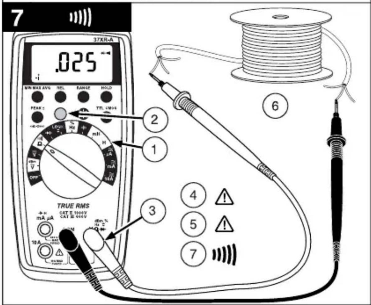
Testing for Continuity See Figure
- Set the Function Switch to
- If is displayed, press the yellow button to display
- Connect the Test Leads: Red to Black to COM
- Turn off power to the circuit being measured.
- Discharge any capacitors that may influence the reading.
- Connect the Test Probes across the resistance.
- Listen for the tone that indicates continuity (< 40)
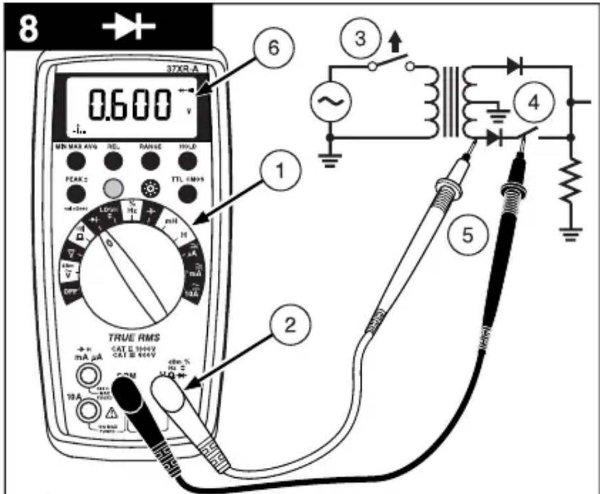
Testing Diodes See Figure
- Set the Function Switch to
- Connect the Test Leads: Red to Black to
COM - Turn off power to the circuit being measured.
- Free at least one end of the diode from the circuit.
- Connect the Test Probes across the diode.
- Read the display. A good diode has a forward voltage drop of about 0.6V . An open or reverse biased diode will read
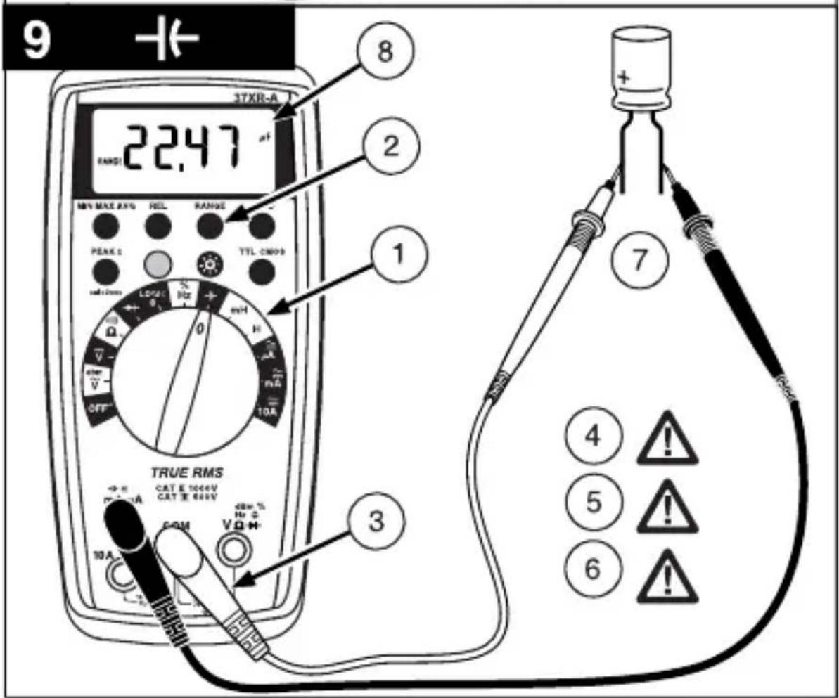
Measuring Capacitance See Figure
- Set the Function Switch to the -function.
- If RANGE is displayed, press the RANGE button to enable autoranging.
- Connect the Test Leads: Red to COM, Black to mA
- Turn off power to the circuit being measured.
- Discharge the capacitor using a 100k resistor.
- Free at least one end of the capacitor from the circuit.
- Connect the Test Probes across the capacitor. When measuring an electrolytic capacitor match the test lead polarity to the polarity of the capacitor.
- Read the display.
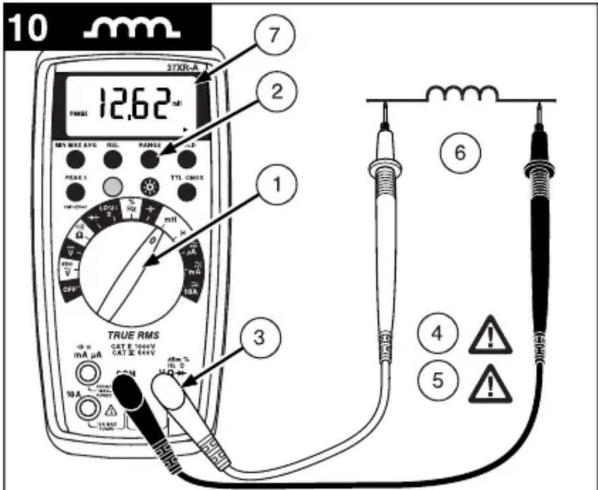
Measuring Inductance See Figure
- Set the Function Switch to mH or H.
- If RANGE is displayed, press the RANGE button to enable autoranging.
- Connect the Test Leads: Red to H mA, Black to COM
- Turn off power to the circuit being measured.
- Free at least one end of the inductor from the circuit.
- Connect the Test Probes across the inductor.
- Read the display.
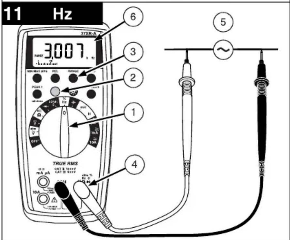
Measuring Frequency See Figure
- Set the Function Switch to Hz.
- If % is displayed, press the yellow button to display Hz.
- If RANGE is displayed, press the RANGE button to enable autoranging.
- Connect the Test Leads: Red to Hz, Black to COM
- Connect the Test Probes to the signal source.
- Read the display.
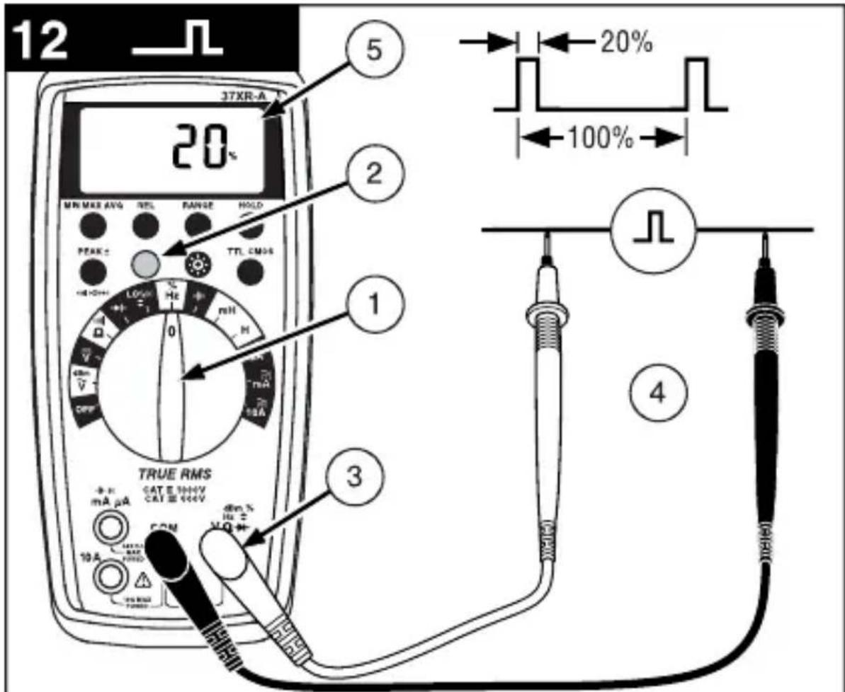
Measuring Dutycycle See Figure
- Set the Function Switch to %.
- If Hz is displayed, press the yellow button to display % .
- Connect the Test Leads: Red to %, Black to COM
- Connect the Test Probes to the signal source.
- Read the display.
Measuring dBm See Figure
The 37XR-A measures dBm relative to 1mW referenced to 50 That is, 10dBm = 10mW , 0dBm = 1mW , -10dBm = 0.1mW , etc.
- Set the Function Switch to dBm.
- Press the yellow button. The display shows dBm to verify the selection.
- Connect the Test Leads: Red to Black to COM
- Connect the Test Probes to the signal source.
- Read the display.
Testing Logic Levels See Figure
The 37XR-A tests logic levels for both TTL and CMOS logic. The meter displays plus a for a high-level (true) condition. The meter beeps and displays an 巧 and a for a low-level (false) condition. See Specifications for the logic 1 and logic 0 voltage limits. Out-of-limits indications are dispalyed as only, no or beep occur.
- Set the Function Switch to LOGIC
- Press the TTL CMOS button to display the selected type.
- Connect the Test Leads: Red to Black to COM
- Connect the black lead to logic common.
- Connect the red lead to the logic test point.
- Read the display.
Additional Features
Input Test Lead Warning
The meter emits a continuous tone when a test lead is placed in the mA or 10A input jack and the Function/Range Switch is not set to a correct current position. (If the meter is connected to a voltage source with leads connected for current, very high current could result). All current ranges are protected by fast acting fuses.
True-rms Measurements
For ac measurements most DMMs average the ac input signal and display the result as an estimated rms value. This average-responding method is accurate for sinusoidal waveforms, but can be very inaccurate for distorted waveforms. To ensure the most accurate measurements, always use a true-rms DMM when measuring ac voltage or ac current on circuits for the following kinds of applications:
- Power Supplies - diodes
- Controllers
Power Limiting - SCR or Triac
Starting - motors - Florescent Lighting - ballasts
- Speed Control - motors
Pulsed Signals - Any non-sinusoidal ac waveform
MIN MAX AVG Measurements
The MIN MAX AVG function reads and updates the display to show the maximum or minimum value measured after you press the MIN MAX AVG button. Pressing the MIN MAX AVG button for less than 1 second will put the meter into a mode of displaying the maximum, minimum, average, or actual readings. Each time the button is pressed, the meter will cycle to the next display mode as shown in the table below. Press the MIN MAX AVG button for more than 2 seconds to disable this feature.
| Button Display Value Displayed | ||
| < 1 second | REC MAX | Maximum value after feature activated |
| REC MIN | Minimum value after feature activated | |
| < 1 second | REC AVG | Average value after feature is activated |
| < 1 second | REC | Actual reading, min max being recorded. |
| >2 seconds Exit MIN MAX AVG | Normal measurement, actual reading | |
Peak Hold Measurements
Note: The PEAK function calibrates itself to meet the specifications.
Peak Hold records and stores the positive and negative peak values that occur while measuring ac current or ac voltage. To enable the Peak Hold feature press the PEAK button for more than 2 seconds. The display will show CAL to indicate the calibration cycle is in process. After the CAL indication clears, press the PEAK button again to display the maximum (P+) value for the ac voltage or ac current being measured. The display will toggle between the P+ and P- readings each time the PEAK button is pressed. Press the PEAK button for more than 1 second to exit the PEAK function.
Beeper Off
The beeper is an aural indicator to identify when the DMM is performing a function, making a range change, detecting a limit, and so on. To disable the beeper use the following procedure:
- Set the Function Switch to OFF.
- Press and hold the HOLD button while turning the Function Switch to the desired function. The no-beep symbol shows on the display.
- Release the HOLD button. The Auto Power Off feature will remain disabled until the meter is turned off and then on.
Note: To disable both the beeper and Auto Power Off press and hold the REL button while turning on the DMM.
Auto Power Off
Auto Power Off is a battery saving feature that puts the meter into a sleep mode if the Function/Range Switch has not changed position in the last 30 minutes. To wake the meter turn it off and then on.
The Auto Power Off feature can be disabled to keep the meter from going to sleep. This feature is useful when using the MIN MAX mode for extended periods. To disable the Auto Power Off feature use the following procedure:
- Set the Function Switch to OFF.
- Press and hold the MIN MAX AVG button while turning the Function Switch from OFF to the desired function. The SLEEP OFF message shows on the display.
- Release the MIN MAX AVG button. The Auto Power Off feature will remain disabled until the meter is turned off and then on.
Note: To disable both Auto Power Off and the beeper press and hold the REL button while turning on the DMM.
REL (Relative) Measurements
The Relative mode displays the difference between the actual reading and a reference value. It may be used with any function or range. To make a relative measurement first establish a reference value by measuring a value and then pressing the REL button after the reading has stabilized. This stores the measured value as the reference and sets the display to zero. The meter subtracts the reference value from subsequent measurements and displays this difference as the relative value. Measurement values greater than the reference value will be positive and values less than the reference value will be negative.
To exit the Relative Mode, Press and hold the REL button for 2 seconds.
HOLD Measurements
The HOLD button causes the meter to capture and continuously display a measurement reading. To use the HOLD feature make a measurement, and then, after the reading has stabilized, momentarily press the HOLD button. You can remove the test leads and the reading will remain on the display. Pressing the HOLD button again releases the display.
Backlight
Pressing the button illuminates the display with a blue backlight. The backlight will automatically turn off in about 60 seconds. Frequent use of the backlight will decrease battery life.
Product Maintenance
Cleaning
To clean the meter, use a soft cloth moistened with water. To avoid damage to the plastic components do not use benzene, alcohol, acetone, ether, paint thinner, lacquer thinner, ketone or other solvents to clean the meter.
Troubleshooting
If the meter appears to operate improperly, check the following items first.
- Review the operating instructions to ensure the meter is being used properly.
- Inspect and test the continuity of the test leads.
- Make sure the battery is in good condition. The low battery symbol appears when the battery falls below the level where accuracy is guaranteed. Replace a low-battery immediately.
- Check the condition of the fuses if the current ranges operate incorrectly.
Battery and Fuse Replacement See Figure
WARNING
To avoid electrical shock remove the test leads from both the meter and the test circuit before accessing the battery or the fuses.
To access the battery and the mA fuse remove the two screws holding the Battery/ Fuse Cover in place, and lift the cover from the meter.
To replace the mA fuse, pry it from its clips using a small screwdriver. A spare mA fuse is located between the battery and the mA fuse.
mA Fuse: Fast Blow .5A/1000V, minimum interrupt rating 30 kA (6.3 x 32 mm) (Amprobe® FP500)
To replace the 10 A fuse: 1) Remove the battery. 2) Remove the four rear-case screws. 3) Separate the case. 4) Remove the 10 A fuse cover. 5) Remove and replace the 10A fuse. 6) Re-install the fuse cover. 7) Reassemble the meter.
10A Fuse : Fast Blow 10A/1000V, minimum interrupt rating 30kA (10 x 38 mm) (Amprobe® FP100).
Repair
All test tools returned for warranty or non-warranty repair or for calibration should be accompanied by the following: your name, company's name, address, telephone number, and proof of purchase. Additionally, please include a brief description of the problem or the service requested and include the test leads with the meter. Nonwarranty repair or replacement charges should be remitted in the form of a check, a money order, credit card with expiration date, or a purchase order made payable to Amprobe® Test Tools.
In-Warranty Repairs and Replacement – All Countries
Please read the warranty statement and check your battery before requesting repair. During the warranty period any defective test tool can be returned to your Amprobe® Test Tools distributor for an exchange for the same or like product. Please check the "Where to Buy" section on www.amprobe.com for a list of distributors near you. Additionally, in the United States and Canada In-Warranty repair and replacement units can also be sent to a Amprobe® Test Tools Service Center (see below for address).
Non-Warranty Repairs and Replacement - US and Canada
Non-warranty repairs in the United States and Canada should be sent to a Amprobe Test Tools Service Center. Call Amprobe Test Tools or inquire at your point of purchase for current repair and replacement rates.
In USA
Amprobe® Test Tools
Everett, WA 98203
Tel: 888-993-5853
Fax: 425-446-6390
In Canada
Amprobe® Test Tools
Mississauga, ON L4Z 1X9
Tel: 905-890-7600
Fax: 905-890-6866
Non-Warranty Repairs and Replacement - Europe
European non-warranty units can be replaced by your Amprobe® Test Tools distributor for a nominal charge. Please check the "Where to Buy" section on www.amprobe.com for a list of distributors near you.
European Correspondence Address*
Amprobe® Test Tools Europe
P.O.Box 1186
5602 BD Eindhoven
The Netherlands
^* (Correspondence only - no repair or replacement available from this address. European customers please contact your distributor).
WARRANTY
This 37XR-A Digital Multimeter is warranted against any defects of material or workmanship within a period of three (3) years following the date of purchase of the multimeter by the original purchaser or original user. Any multimeter claimed to be defective during the warranty period should be returned with proof of purchase to an authorized Amprobe® Test Tools Service Center or to the local Amprobe® Test Tools dealer or distributor where your multimeter was purchased. See Repair section for details. Any implied warranties arising out of the sale of a Amprobe® Test Tools multimeter, including but not limited to implied warranties of merchantability and fitness for a particular purpose, are limited in duration to the above stated one (1) year period. Amprobe® Test Tools shall not be liable for loss of use of the multimeter or other incidental or consequential damages, expenses, or economical loss or for any claim or claims for such damage, expenses or economical loss. Some states do not allow limitations on how long implied warranties last or the exclusion or limitation of incidental or consequential damages, so the above limitations or exclusions may not apply to you. This warranty gives you specific legal rights, and you may also have other rights which vary from state to state.
Specifications
General Specifications
(Stated accuracy at 23^± 5^, < 75% relative humidity.)
Display: 4 digit liquid crystal display (LCD) with a 41 segment analog bargraphic.
Auto ranging: 9999 counts
Manual ranging: 9999 counts
Polarity: Automatic, positive implied, negative polarity indication.
Overrange: (OL) or (-OL) is displayed.
Zero: Automatic.
Low battery indication: The is
displayed when the battery voltage drops below the operating level.
Auto power off: Approx. 30 minutes.
Measurement rate: 2 times per second, nominal.
Operating environment: 0^ to 50^ at < 70% R.H. For all functions except 10A ranges
10A ranges: 0^ to 40^ at < 70% R.H.
Storage temperature: -20 °C to 60 °C, 0 to 80 % R.H. with battery removed from meter.
Temperature Coefficient: 0.1 × (specified accuracy) per ^ C . (0 °C to 18 °C, 28 °C to 50 °C).
Altitude: (2000 m) 6562 feet
Power: Single standard 9-volt battery, NEDA 1604, JIS 006P, IEC 6F22.
Battery life: 75 hours typical with carbon-zinc. 150 hours typical with
alkaline. Using the backlight will decrease battery life.
Dimensions:
196 mm (H) ×92 mm (W) ×60 mm (D).
Weight:
with battery and holster, 482 grams Box contents:
Test leads/w alligator clips 1 set
Users Manual 1
Magne-Grip Holster 1
Clip, magnet, and strap. 1
9V battery (installed) 1
spare mA fuse 0.5A/1000V 1
Approvals:
Safety: Conforms to EN61010-1:2010;
EN61010-2-033:2012:Cat II - 1000V / Cat
III - 600V; Class 2, Pollution degree II; UL61010-1
C 950Z
EMC: Conforms to EN61326-1.
This product complies with requirements of the following European Community Directives: 89/336/EEC (Electromagnetic Compatibility) and 73/23/EEC (Low Voltage) as amended by 93/68/EEC (CE Marking). However, electrical noise or intense electromagnetic fields in the vicinity of the equipment may disturb the measurement circuit. Measuring instruments will also respond to unwanted signals that may be present within the measurement circuit. Users should exercise care and take appropriate precautions to avoid misleading results when making measurements in the presence of electronic interference.
Electrical Specifications
DC VOLTS
Ranges: 1000mV, 10V, 100V, 1000V
(Auto/Manual ranging)
Resolution: 100 V
Accuracy: ± (0.1% rdg + 5 dgts)
Input impedance: 10M
Overload protection: 1000 V dc or 750
V ac rms
AC VOLTS TRUE RMS (45 Hz - 2 kHz)
Ranges: 1000mV 10V,100V,750V
(Auto/Manual ranging)
Resolution: 100 V
Minimum reading on 1000mV range:
14mV
Accuracy:
± (1.2% rdg + 10dgts)45Hz to 500Hz
± (2.0% rdg + 10dgts)500Hz to 2kHz
± (2.0% rdg + 10dgts)45Hz to 1kHz on
750 V range
Peak Hold accuracy: ± (3.0% +200 dgts) on 100V,750V range
1000mV, 10V ranges unspecified
Crest Factor: ≤ 3 Input impedance: 10M AC coupled true rms specified from 5 % to 100% of range
Overload protection: 1000Vdc or 750 V ac rms
DC CURRENT
Ranges: 100 A 1000μA, 10mA, 100mA, 400mA, 10A (Auto/Manual ranging)
Resolution: 0.01 A
Accuracy:
± (0.5% rdg + 10dgts) on 100 A range
± (0.5% rdg + 5dgt) on 1000 A to 400mA ranges
± (1.5% rdg + 10 dgts) on 10A range
Input protection: 0.5A/1000V fast blow ceramic fuse 6.3 × 32 mm on A / mA input 10A/1000V fast blow ceramic fuse 10 × 38 mm on 10A input
10A input: 10 A for 4 minutes maximum followed by a 12 minute cooling period Burden voltage:
A Range: 1mV / 1 A
mA Range: 10mV / 1mA
A Range: 35mV / 1 A
AC CURRENT TRUE RMS (45 Hz to 1 kHz)
Ranges:100μA, 1000μA, 10mA, 100mA, 400mA, 10A (Auto/Manual ranging)
Resolution: 0.01 A
Accuracy:
± (1.5% rdg +10 dgts) on 100 A to 100mA ranges
± (2.0% rdg +10 dgts) on 400mA range
± (2.5% rdg + 20 dgts) on 10A range
Peak Hold accuracy: ± (3.0% + 200 dgts) 100 A range unspecified
Crest Factor: 3 ≤
AC coupled true rms specified from 5% to 100% of range
Input protection: 0.5A/1000V fast blow ceramic fuse 6.3× 32mm on A / mA input
10A/1000V fast blow ceramic fuse 10× 38mm on 10A input
10A input: 10 A for 4 minutes maximum followed by a 12 minute cooling period Burden voltage: See DC Current
RESISTANCE
Ranges: 1000Ω, 10kΩ 100kΩ 1000k, Ω
10MΩ 40M (Auto/Manual ranging)
Resolution: 100 mΩ
Accuracy: ± (0.5% rdg + 8 dgts) on 1000 to 1000kΩ ranges
± (1.0% rdg + 10dgts) on 10MΩrange
± (2.0% rdg + 10 dgts) on 40MΩrange
Open circuit volts: -0.45 V dc typical Overload protection: 1000 V dc or 750 V ac rms
CAPACITANCE
Ranges: 40nF, 400nF, 4 F 40 F400uF (3999 counts) (Auto/Manual ranging) Resolution: 0.01 nF
Accuracy: ± (3.0% rdg + 10 dgts) on 40nF, 400uF ranges
± (3.0% rdg + 5 dgts) on 400nF to 40uF ranges
Test voltange: < 1V
Test Frequency: 1.3Hz on 40nF to 40 F ranges; 0.7Hz on 400 F range
Input protection: 0.5A/1000V fast blow ceramic fuse 6.3 × 32 mm on A / mA input
INDUCTANCE
Ranges: 4mH, 40mH, 400mH, 4H, 40H (3999 counts) (Auto/Manual ranging) Resolution: 1 H
Accuracy: ± (5.0% rdg + 30 dgts)*
*For values of Q ≤ 7
Test frequency: 1kHz on 4mH , 40mH ranges, 200Hz on 400mH to 40H ranges. Input protection: 0.5A / 1000V fast blow ceramic fuse 6.3× 32mm on A / mA input
FREQUENCY
Ranges: 100Hz, 1000Hz, 10kHz, 100kHz, 1000KHz, 10MHz, (Auto/Manual ranging)
Resolution: 0.01 Hz
Accuracy: ± (0.1% rdg + 5dgts)
Sensitivity: 3Hz to 1MHz: >1.5 V rms;
1MHz to 10MHz: >2V rms, <5V rms
Minimum input range: 100Hz range > 3
Hz, 1000Hz range >30Hz
Minimum pulse width: >25 ns
Duty cycle limits: >30% and < 70%
Overload protection: 1000 V dc or 750
V ac rms
DUTY CYCLE
Ranges: 0 to 90%
Resolution: 0.01%
Pulse width: >10 us
Frequency range:
0% to 10% (40 Hz to 990 Hz)
10% to 90% (40 Hz to 20 kHz)
Accuracy: (5 V logic) ±(2.0 % rdg + 20 dgts)
Overload protection: 1000 V dc or 750
V ac rms
LOGIC TEST
Logic Type: TTL, CMOS
Thresholds Logic 1 (Hi):
TTL: 2.8V± 0.8V CMOS: 4V± 1V
Thresholds Logic 0 (Lo):
TTL: 0.8V± 0.5V CMOS: 2V± 0.5V
Test Voltage: TTL: 5 V dc, CMOS: > 5 V dc and < 10 V dc
Frequency Response: 20 MHz
Pulse Width: 25 ns min
Duty Cycle: >30% and < 70%
Indication: 40 ms beep at logic 0 (LO)
Overload protection: 1000 V dc or 750
V ac rms
dBm
Ranges: -13dBm to + 50dBm
Resolution: 0.01 dBm
Accuracy:
± 0.7 dB + 8 dgts (45 Hz to 5 kHz)
± 2.5 dB + 8 dgts (5 kHz to 10 kHz)
Reference impedance: 50
Input protection: 10M
Overload protection: 1000 V dc or 750
V ac rms
CONTINUITY
Audible indication: Less than 40
Response time: 100 ms
Overload protection:1000 V dc or 750
V ac rms
DIODE TEST
Test current: 1.0mA (approximate)
Accuracy: ± (1.5% rdg + 5 dgts)
Resolution: 1mV
Open circuit volts: 3.0 dc typical
Overload protection:
1000 V dc or 750 V ac rms mA, 10A jack:
Input warning detects wrong function selection
AUXILIARY FEATURES
MIN/AVG/MAX: Displays the maximum, minimum, or average reading following a MIN, MAX, or AVG selection.
DATA HOLD: Freeze the latest reading on the display.
REL: Initiates relative measurements.
PEAK: Record the peak+ or peak value in a measurement. It is usable with ac voltage, ac current measurements. If the pressed time >2 seconds, the PEAK function will enter the calibration mode; the LCD will show CAL and the internal buffer will remember the internal offset voltage then go back to the measure mode.
RANGE: Initiates manual-range selection.
Backlight: Backlight auto-off approx.
60 seconds
TTL/CMOS: Shift LOGIC TTL or CMOS
Shift: Shift dBm, ACA, continuity, DUTY CYCLE
REPLACEMENT PARTS
TL36 Test Lead Set with Alligator clips
FP500 mA fuse - Fuse Pack 0.5A/1000V (4 each)
FP100 10A fuse - Fuse Pack 10A/1000V (2 each)
XR-H2Magne-Grip Holster, clip, magnet, and strap

| 3 True rms | 37XR-A AC Trus rms * | |
| Input Waveform Signal d'entrée Eingangsschwingungsform Forma d'onda d'ingresso Forma de onda de entrada | ||
| Sine Wave Sinusoïdale Sinusschwingung Onda sinusoidale Onda sinusoidal | +Vpeak 0 -Vpeak | .707× Vpeak CF = 1.414 |
| Full Wave, Sine Wave Onde complète, Sinusoïdale Volle Schwingung, Sinusschwingung Onda sinusoidale, onda intera Onda completeness, Onda sinusoidal | Vpeak 0 | 0.308 × Vpeak CF = 3.247 |
| Half-Wave, Sine Wave Demi-onde, sinusoidale Halbschwingung, Sinusschwingung Onda sinusoidale, semionda Media onda, onda sinusoidal | Vpeak 0 | 0.386 × Vpeak CF = 2.591 |
| Square Wave Onde carrée Rechteckschwingung Onda quadra Onda cuadrada | Vpeak 0 Vpeak T0 | T1 T0 = T1 | 1.000 × Vpeak CF = 1.000 |
| Square Wave Onde carrée Rechteckschwingung Onda quadra Onda cuadrada | Vpeak 0 T0 | T1 T0 = T1 | 0.500 × Vpeak CF = 2.000 |
| Pulse Wave Onde impulsionnelle Impulsschwingung Onda dell'impulso Onda de impulsos | pask 0 b c d = b/c K = √D-D2 | Vpeak × K CF = 1/K |
| Sawtooth Wave Onde en dent de scie Sägezahnschwingung Onda a denti di sega Onda diente de sierra | +Vpeak 0 -Vpeak | 0.577 × Vpeak CF = 1.733 |
| * CF = Crest Factor, Crest Factor = Vpeak/Vrms | ||
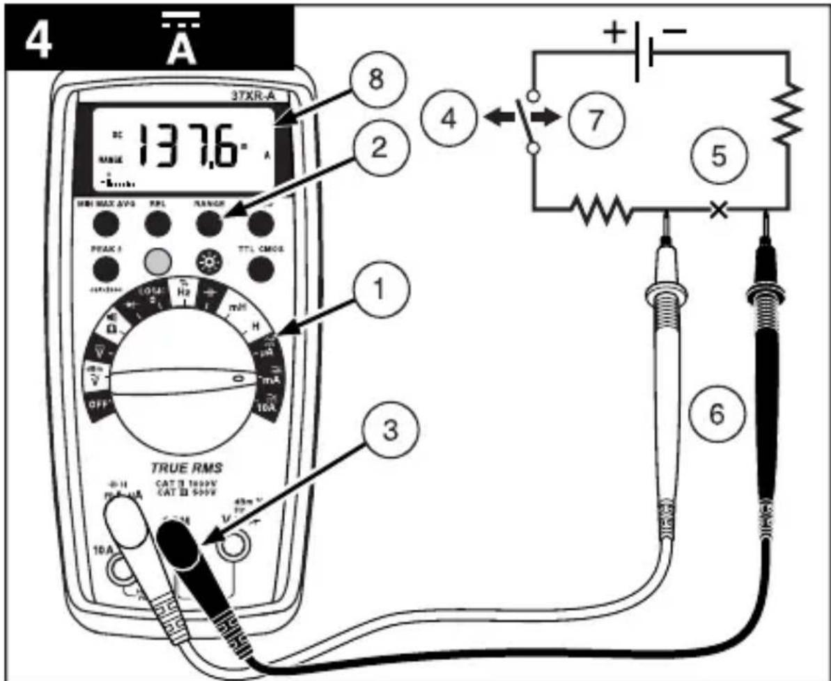


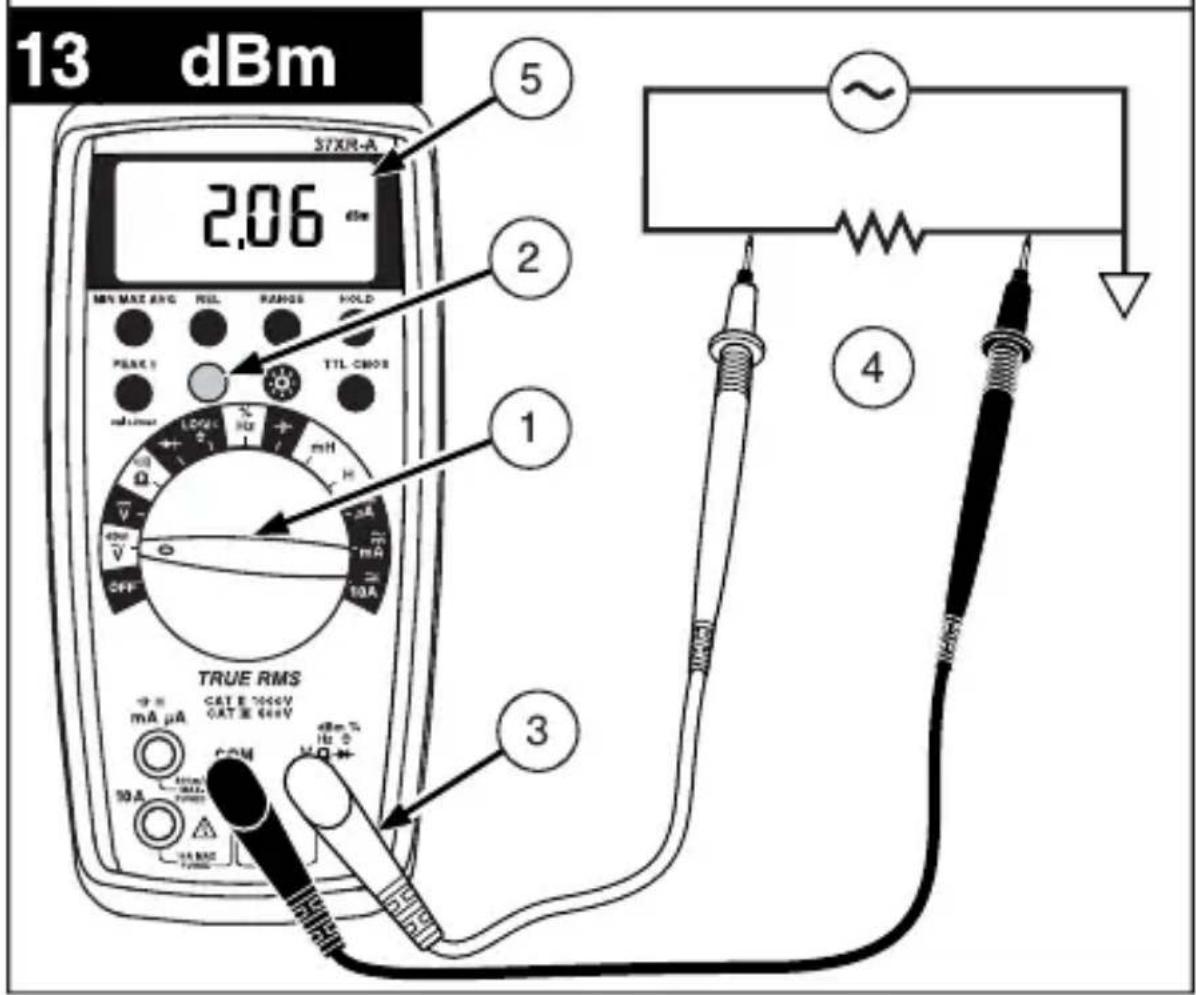
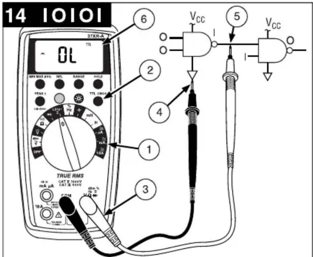
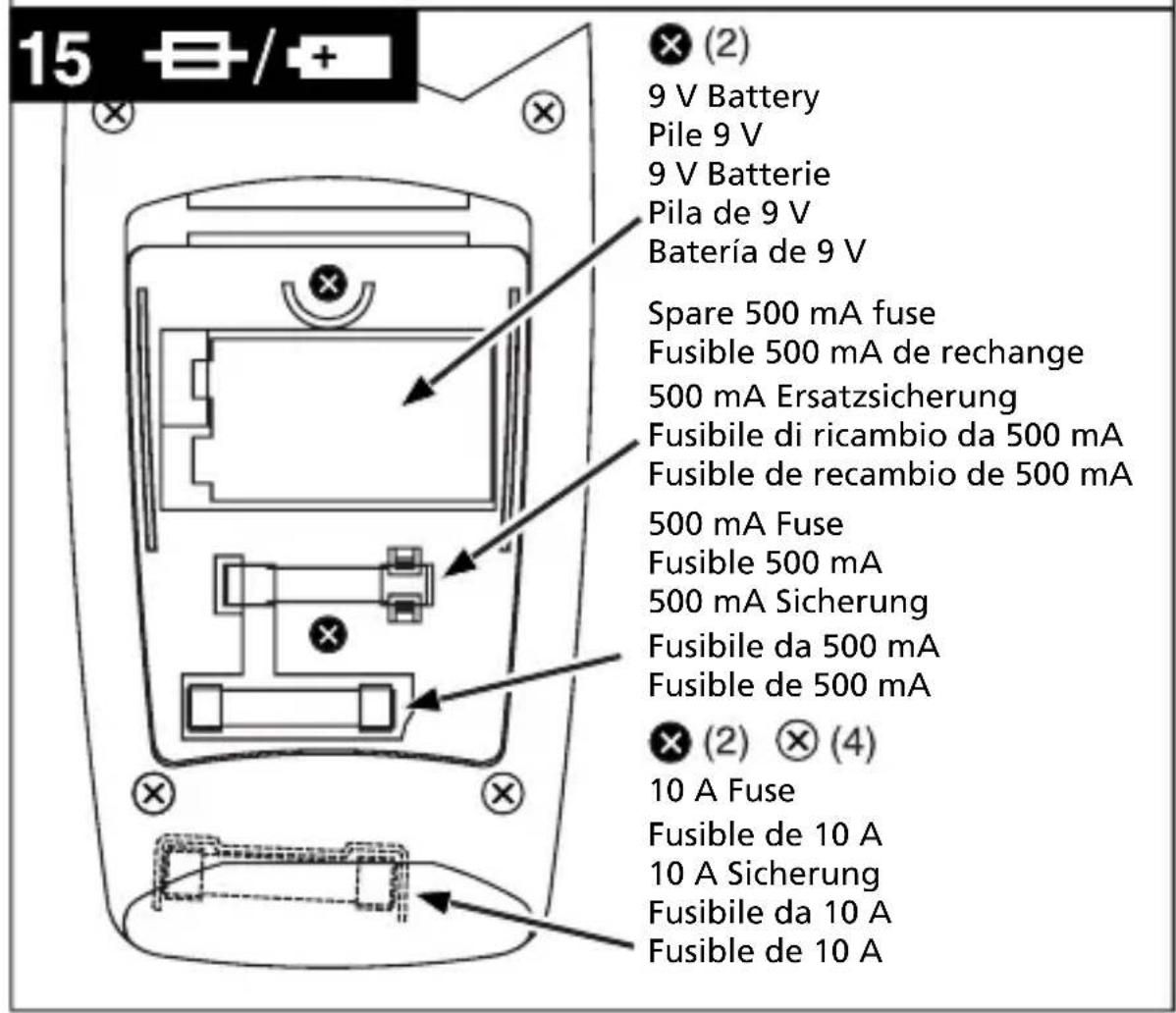
Table des matieres
Mesures relatives (REL) 8
Mesures en maintien HOLD 8
Retroeclairage 8
Mesures relatives (REL)
0% to 10% (40 Hz à 990 Hz) 10% to
Symbole in thisem Handbuch 2
Einleitung 3
Symbole in thisem Handbuch
uF (3999 Counts) (Autom./Manuelle
Bereichswahl)
Auflosung: 0.01 nF
Portate: 100 Hz, 1000 Hz, 10 kHz, 100
0% to 10% (40 Hz a 990 Hz)
10% to 90% (40 Hz a 20 kHz)
Resolution: 0.01 A
Exactitud:
± (1.5% lect. + 10 digitos) en los rangos de 100 A a 100mA,± (2.0% lect. + 10 digitos) en los rangos de 400mA
Resolution: 0.01%
Anchura del impulso: >10 us
0% to 10% (40 Hz a 990 Hz)
10% to 90% (40 Hz a 20 kHz)
TTL (CLTT): 2.8 V ± 0.8 V, CMOS (SCOM): 4 V ± 1 V
Resolution: 1mV
Symbols Used in this Manual 2
Introduction 3
Making Measurements 3
Verify Instrument Operation 3
Range Selection 3
Correcting an Overload OL or Indication 3
Measuring DC Voltage. See Figure -1 4
Measuring AC Voltage (True rms) .See Figure -2- & -3- 4
Preparing for Current Measurements 4
Measuring DC Current. See Figure 4.
Measuring AC Current (True rms) .See Figure -3- & -5- 4
Measuring Resistance . See Figure 6. 5
Testing for Continuity. See Figure 7. 5
Testing Diodes . See Figure -8- 5
Measuring Capacitance. See Figure 9. 5
Measuring Inductance. See Figure 10-6
Measuring Frequency. See Figure -11 6
Measuring Dutycycle. See Figure -12- 6
Measuring dBm. See Figure -13- 6
Testing Logic Levels. See Figure 14-6
Additional Features. 7
Input Test Lead Warning 7
True-rms Measurements. 7
MIN MAX AVG Measurements 7
Peak Hold Measurements. 7
Beeper Off. 8
Auto Power Off. 8
REL (Relative) Measurements. 8
HOLD Measurements 8
Backlight 8
Product Maintenance. 9
Battery and Fuse Replacement. See Figure -15- 9
Repair 9
WARRANTY 10
Specifications 11
Manual Supplement 37XR-A Users
1. Display
Afficheur
Anzeige
Display
Pantalla
5. Strap Clip
Clip de bretelle
Klemme
Clip in velcro
Clip para correa
2. Feature Buttons
6. Battery/Fuse Cover
3. Function/Range Switch
4. Test Lead Connections
IodrotOBka K n3MepeHnMaToka
- Otklioute nitaHne cei nepeid nodknueHem uynob.
- Ecπινι3MερασεMbιTOK πρεΒbIωaet 10 A, daητe πριδόργ oxλαπιTBcγ B προΜεχγTkax MEXKdy Μ3MερεHημM.
- Pn noKlueyHn 7yna K BxOy ToKa nepeB bIbOpom yHKuN ToKa, NOBtCra 3ByKOBoI npEduPexJaIOUsn CunHaJ.
- HanpajkeHne xOJIocToro xOda B TOUKe n3MepeHn He DoJIxHO ppeBbIaTb 1000 B.
Bcerda n3MepaTe TK, noDKIIOUaCb nocJeIOBaTeNbHO c Harpy3KoH. HkoRda He n3MepaTe TK npaJIneJbHo nCTOuHnky HanpjaKeHn.
I3mepenHe nocToHHoro ToKa Cm. pnc.
- BbIbepeTe nepeKIIHouaTeJIeM HxKHyIO yHKnUIO μA (MKA), mA (MA) IJIN 10A.
- EcniФункця 10A He BbIbpaHa, n HaДиСпгee OTo6paxaetcRANGE (Диana3OH), HaxmTe KHOKNy RANGE (Диana3OH), YTO6bI BKJIIOHTb aBTOMaTnueckn Bbl6Op npedeNoB n3MepeHn.
- Pódklounte uynbI: KpacHbI K μA (MKA), mA (MA) nII 10A, ČepHbI K COM (O6u)
- OTKJIIOHTe NITaHne N3MepeMoN cenn.
- Pa3OMKHInTe HcNbITbIbAeMyIO cenb (→-), YTO6bl yCTaHOBnTb TOUKN 3MEpeHnI.
- Noknoute uynb noceobatehC harpy3kO.
- BkIIOUHTe nITaHHe n3MepReMoN cenn.
- NocmoTpne Ha dncnne, ecn Heo6xoDIMO, ycTpaHnte neperpy3ky (aL nn -aL).
I3mepenne npemehnHO TOKa (NCTINHHe cpeDHeKBaApTaNuHoe
3haueHne)
Cm.pnc.-3- n-5-
YTo6bI y3HaTb IpeMMyIeCTBa IcTINHOrO cpeIHeKBaIpaTnHOrO 3HaueHnra, cm. pa3JeI "DononHntelbHbIe yHKuN".
- BbI6epTe nepeKJIIOuATEIeM HUxHHyO cyHKUIO I dHaIa3OH μA (MkA), mA (MA) 10A.
- Ecn Ha nucnnee oTo6paXaetcra DC (noCT. Tok), HaxMnte JKeIyIO KHOIIky, UTo6bl BKJIOHTb AC (nepeM. Tok).
- Ecπη φυκιγμA (mKa) Μινn mA (mA) He BbIbpaHa, Ι Ha πιπηe OTObpaXaETcR RANGE (ДиаэзОH), HaxMnte KHOJky RANGE (ДиаэзOH), YTO6bl BKIIQUHTb aBTOMaTnueckn BbIbop npedeJIOB n3MepeHn.
- Поdkлочи Te uynы: KpacHyн k μA (mKA), mA (MA) nIn 10A, cheHyн k COM (Obun)
-
OTKJIIOHTe NITaHHe N3MepeMoN cenn.
-
Pa30MKHnte HcNbITbIbAeMyIO cIeNb (), Xro6bl yCTaHOBHTb TOUKN 3MepeHnJ.
- Nooknoute uynbI nocneObaTeJbHo c harpy3KoN.
- BkIIOUHTe nITaHHe n3MepeMoM ueHn.
- ПосмOTРе на диспей, ecг Heo6xOДМо, устрант epeperpy3ky (L).
I3mepenhe co npotnbneHnA Cm. pnc.
- YctaHOBnTe yHKUHOHaIbHbI nepeKIOuOaTeIb B NOIOXeHne
- Ecnn ha dinncnee oTo6paXaetc , HaxMnte XeJTyO KHOkY, YTO6bl nOBuIOcb
- Ecnn Ha dincnee oTo6paJaaetcRANGE (Dnana3OH), HaxMITE KhoNky RANGE (Dnana3OH), YTObI BKJIIOHTb ABTOMaTNUeCKn BbIbOp IpeJeNa n3MepeHna.
- Nooknounte uynb: Kpacnb K Vepnb K COM (O6u)
- OtklnoHTe nHTaHne n3MepReMoI cENn. HnkOrda He n3MepRrTe coPOTuBHeHne napaJIleNbHO nCTOuyHKy HanpJxEHn IIN B cENn nHTaHn.
- Pa3pIe BCE KOHcHCaTOpbl, KOToPbIe MOrTy NOBnIaTb Ha pe3yIbTaT I3MepeHInr.
- Nooknoute uynbnapaJIeIbHO cnpotNBeneHIO.
- Chnmtte noka3aHna c dncnpe. Ecnn noBntc o L ha camom 6oNbwoM dnaana3OHe, coPOTNBHeHne cNtKOM 6oNbwoe.
IcnbitaHne Ha o6pbB Cm. pnc.
- YCTAHOBnTE yHKnIOHaJIbHbI nepeKlNoaTeJIb B NOJoxeHne
- Ecnn Ha nucnnee oTo6paxaetcra, Haxmnte XeI TYKHOKNy, YTO6bl NOBnIOcb
- Pooknounte uynb: Kpacnb K Vepnb K COM (O6uui)
- OTKJIHOUHTe IITaHHe N3MepReMoN UeHN.
- Pa3pIe BCE KOHcHCaTOpbl, KOToPbIe MOryT NOBnIaTb Ha pe3yIbTaT N3MepeHna.
- Nooknoute uynbnapaJIneIbHO cnpotNBHeHIO.
- IpocnywaTe ToHObBcHnA, yka3bBaHOuN Ha ceNoCTHoCTb cenn (< 40Ω).
PpOBePKa DnOoB Cm. pnc.
- YctaHOBnte cyHKUHOHaJIbHbI nepeKJIIOuTaTeJb B NOJOKeHne
- POnKnIouHTe 乌ynb: KpaChbI K VyeepHbIK COM (O6uui)
- OTKIIOHTe IITaHHe N3MepeMoN LcEN.
- OTKIHOHTe XOTa 6bl OIN BBIBOD IIOda OT cENI.
- NooknIOUHTe uynbI npaJIneIbHO nIOy.
- CHIMITE NOKA3AHNA C DnCnJIe. Ha XopoWem DNoDe npraMoe NapeHne HAnpJKeHNA COCTABJIeT OKOIO 0,6 B. O6paTHO-CMeUeHHbI JNoD INI DNOD C o6pbIBOM NOKaXeT O L.
I3mepenhe emkoctn Cm. pnc.
- YcTaHOBnTe 0yHKUHOHaIbHbI nepeKIOuAteJIb B NOLOKeHne
- Ecnn Ha dncnnee oTo6paxaetcRANGE (Dnaana3OH), HaxmTe KhoNky RANGE (Dnaana3OH), YTObbl BkIIOHTb ABOtOMaTHueckn BBi6Op npedeJa n3MepeHnra.
- Pooknounte ynbI: KpacHbIK COM (O6uH), YepHbIK mA (MA)
- OTKIHOHTe NITaHHe N3MepReMoN ZeEN.
- Pa3pIte KOHdEHCaTOp c NOMOu bU pe3nctopa 100 KΩ.
- OTKIHOHTe XOTa 6bIOHN BBIBOD KOHDeHcaTopa OT cenn.
- Поdkлочite упьnapаллельно кондсатopy. Ри Измерени эльктолчеснх кондсаторов поларно Должна coьада т с поглесъю кондсаторa.
- CHIMITE NOKa3aHnC dNcJIpe.
I3mepenHe HndyKtNBHOCTN Cm. pnc.
- YctaHOBnTe yHKUHOHaJIbHbI nepeKIIuOaTeJIb B noIOKeHne mH (MTH) H
- Ecnn Ha dincnee oTo6paxaetcra RANGE (Dnana30H), Haxmnte KhoNky RANGE (Dnana3OH), TTO6bI BKNIOHTb ABTOMaTHueckn Bbl6Op npedeJa N3MepeHna.
- NoknHnTe uynb: KpacnbK (rH) mA (mA), Yephbl K COM (O6uui)
- Otklouhte nItaHne n3mepreMoI cenn.
- OTKIIOHTe XOTa 6bI OINH BbIBOD INHdyKTNBHOCTN OT cENN.
- NpdkJIIOUHTe UynbI npaJIneJbHO INyKTHBHOCTN.
- CHIMITE NOKa3aHnC dncnneJ.
I3mepenhe yactotbl Cm. pnc.
- YcTaHOBnTe yHKUHOHaJIbHbI nepeKNIouaTeIb B nOIOKeHne Hz (T).
- Ecni Ha dinpnee oTo6paKaetc % , HaxMnte JxelTyIO KhoNky, YTObI NOBnOocb Hz (T).
- Ecn Ha dncnlee oTo6paKaetcRANGE (Dnaana3OH), HaxMnte KhoNky RANGE (Dnaana3OH), YTO6bl BkJIOnuTb aBtOMaTuYeckn Bbl6Op npedeNa u3MepeHna.
- Noknoute uynb: Kpacnb K Hz (T), Yepnb K COM (O6u)
- NookJIIOUHTe UynbI K NcTOnHnky CnHaHa.
- Chmnte noka3aHn c dncnne.
I3mepenHe Ko3oΦpHnueHtA 3aOpJHHeHnCm. pnc.
- YctaHOBnte cyHKUHOHaJIbHbI nepeKJIIOuTaTeIb B NOJIOXHeHne %.
- Ecnn Ha dncnnee oTo6paxkaetc Hz (T), haxmte XeNTyIO KONky, T06bl NOBnOcB %.
3.Поdkлочи Teуны:КpacHyB K %,ЧерHyB K COM (O6uH) - NooknouHTe yynbIK nCTOHyCnHaJa.
- Chmnte nokaahna c dncnne.
I3mepenhe dBm (dBm) Cm. pnc.
Ipn6op 37XR-A no3B0JraET n3MepeNTb dBm (dM) oTHocHTeNbHO 1 mBT npn 50Ω (OM). To eTb, 10 dM = 10 mBT, 0 dM = 1 mBT, -10 dM = 0,1 mBT n T.Д.
- YctaHOBnTe 4yHKUHOHaBHBI nepeKIOuATEb B noJIOKeHne dBm (d6M).
- HaxMMTe XeIyIO KhoNky. Ha dncnnee oTo6pa3ntbcra dBm (d5M), nna KOHTpOJIa BbIbopa.
- NpoknHte ynb: KpaChbK VΩ→, YepHbK COM (O6nn)
4.Поdkлючп TeунькИСТОУнky CnHana. - Chmnte noka3aHna c dncnne.
A B T O M A T H U C E C K O E O T K I N H O U E H E N E P I T A H N I P P E D C T A B L E R T C O B O F y H K C H I O C O X P A H E H N I 3 a p r d a b a t a p e n, K O T O P A I P E B O D I N T P P I B O B B J D Y U S N I P E K I M, E C N I P E P E K N I O U A T E N B F y H K C H I N / D I N A P A Z O H A H E N C P O N B 3 O B A N C B A N C B I N O C P E D H N E 30 M H Y T. U T O B I B O 3 0 6 H O B N T B p a b O T Y, B b I K I N O U H I T E P P I B O P I N B K I N O U H I T C H O B A.
Функлio abTomatueckoro BbIKIIOUeHnЯ NITaHnЯ MoXHO OTKIIIOHTb, YTObI MyIbTUMeTp He BXODINB XdyuynpeKIM. 3To IOne3HO pRn IOnyueHnMaKC.NMn. 3NaueHn B TeueHne DInTeNbHO repnoDa BpemeHn. YTObl OTKnIOHTb φyHKlIOABTomatueckoro BbIKIIOUeHnЯ NITaHnra, BblONIHrTe CNeedyUOuine DeiCTBn:
- YctaHOBnTe cyHKUHOHaIbHbI nepeKlOuTaTeIb B noIOXeHne OFF (BblkJI.).
- Haxmte n ydepknae KhoNky MIN MAX AVG (MnH./MaKc. cpe.) npu ycTaHOBKe FyHKUHOHaJIbHOI nepeKnOaTeTn 3 noLoKeHnA OFF (BbIK.) B HyxHyo FyHKUHO. Ha dncPJIee NORBtCra coo6ueHne SLEEP OFF (Xdyu npexn m OTKIOUeH).
- OTnycTe KhONky MIN MAX AVG (MnH./MaKc. cpeI.).Функия aBTOMaTHueCKOrO BbIKNoyeHnI NITaHnOCTaETcR OTKJIIOUeHHoN Do Tex nOp, IOKa MyJIbTImMeTp He BbIKJIIOuHTb, a 3aTeM He BKJIIOuHTb CHOBa.
IpymeaHne: UTo6bI OTKIOUHTb yCTpoiCtBO 3ByKOBO rHaJa n cyHKuio aBToMaTHueCKOro OTKIOUeHn IITaHnI, HaxMnte u ydepXINBaIte KHOkky REL BO BpeM yCTaHOBKn nepeKIOUaTeI B HxKHyIO cyHKuio.
I3mepeHnB OTHOCHTeHbHom pexime REL (OTHOCTeHbHbI peXIM)
PexMM Relative (OTHOCNTeBbHbIpeKIM) NO3BOJnE TOKa3aTb pa3JIuue MeJx dy fakTneckm Ioka3aHem m 3HaueHHeM. OH MOKeT npImeHrbcra C IIObof cyHKUeN ININ pRn IIObOM dnaNa3OHe n3MepeHn. YTo6bl npOBectn OTHCNTeBbHOe 3MaPeHne, CHaAa yCTaHOBtE 3Ta1oHHOe 3HaueHne n0 n3MepeHHOMy 3HaueHNO, a 3aTe M HaxMtte KONkY REL (OTHCNTeBbHbI peKIM) Nocle cTa6NJn3aCnn noka3AHn. Ppi 3Tom n3MepeHHoe 3HaueHne coXpaHReTcKa k 3Ta1oHHOe, a Ha DnCnlee OTO6paxKaETc Hyn. Pnp6op BbIHTaet 3Ta1oHHOe 3HaueHne n3 NocJeDyUOux pe3yNbTaTOB n3MepeHn, a pa3HNuy OTO6paxKaET kAK OTHCNTeBbHOe 3HaueHne. n3MepeHHbIe 3HaueHn, KOtOpBe 6OJbWe 3Ta1oHHOr o BydTu CO 3HaKOM IIIOc, a KOtOpBe MeHbSe - CO 3HaKOM MMHyC.
YTo6bI BbIITn I3 OTHOCHTeNbHOro peXIMa, HAXMITE u ydepxNBaTe KHOKy REL B TeueHne 2 ceKyH.
I3mepenBpeXnme Hold (Kcaun daHbIX)
KhoNka HOLD (ФИКСАЦЯ DAHнБИ) NO3BOJЯET MyЛТIMeTpy NOJUyAыpe3yЛьТаТы ИЗМерEHи IN HeNpepbIBHNO nOKa3bIBaTB nX HaДиCпл.e. YTO6bl BOCNoIb3OBAtbcR peXIMOM HOLD (ФИКСАЦЯ DAHнБИ), npOBeДNTe n3MepEHnE, a 3aTeM, nocJIe cTaBnIN3aUNn NOKa3aHn, HeMeДЛeHNo HAXMITE KONkY HOLD (ФИКСАЦЯ DAHнБИ). Uybl MOxHо ChrTb, Ho NOKa3aHn8 6dUT OCTaBaTbCra HaДиCпл.e. YTO6bl OuNCTntb 3KpaH, CHOBA HaxMITE KHOKNy HOLD (ФИКСАЦЯ DAHнБИ).
PocBetka
Ponck nyctpaHHe HeNCnPaBHOCTeI
Ecn np6op cTan pa6oTaB He npaBnIbHo, Chauana npOBepbTe cNeDyUOuNE KOMNOHEHTbl.
- O3HaKoMbTeCb C INHCTpyKcIyMaMn NO 3KcIIyatauN, YTO6bl IpaBnIbHO pa6OtaTb C np6Opom.
2.ПроверъпOTсуТСВиообьIBOBвунax. - Y6eHNTecb, yTO 6aTapeB XOPOwEM COCToHNN. Pn Hn3KOM 3apJe 6aTapeN (HnKe yPoBn, npN KOtOpom rapaHTnpyETcra Tpe6yeMaJ ToHocTb) NOBnReTcA COOTBeTCTByIOuI N 3NaOH KHeMeDJIeHHO 3aMeHInTe pa3pXeHHyIO 6aTapeIO.
- Поберпесостаянne пededoxpaHITeNe, ecnДиana3ObI ДЯТOKOB pa6oTaOT HENpaBnJIbHo.
3aMeHa 6aTapeN n npedeoxpaHnteJe Cm. pnc.
PENEYUNPEXKDEHNE!
Ipeed 3aMeHoi 6aTapei n npedeoxpaHnteNe, yTo6bI He donyctntb ydapa 3JIeKTPnueckm TOKOM, OTKnIOHTe Uynbl OT npnbopa N OT n3MepreMoN cenn.
UTo6bI Do6paTbcra do 6atapeu n npedeoxpahnteMa, cHIMtTe Dba BnHTa KpeJIneHna KpbIshK batapeu/npeOxpaHnteYn noHNMTe KpbIshKy.
ДяЗamHeI npedoxpaHnteMa OToDBnHbTe ero 3axmblc NOMOuH He6oJIbwoi OTBepTK. Mexdy 6aTapeen I npedoxpaHnteJeM Ma HaxoDntc 3anachon npedoxpaHnteMbA.
IpeoXaHnteMa: BbICtpOeJeCTBHyOuN 0,5 A / 1000 B, MmHmAlhBHy npOBeH npepbBaHn 30 kA (6,3 x 32 MM) (Amprobe FP500)
UTo6bI 3aMeHnITb npEdoxpaHnte10A:1) Chmnte 6aTapeo.2) Chmnte YeTbipe BnHTa Ha 3aHne cToPoHe Kopnyca.3) Pa3dJeNITE KOpNyc.4) Chmnte KpbIshky npedoxpaHnte10A.5) IV3BLeKInTe cTapbI npEdoxpaHnteJIb N yCTaHOBnTe HObIy npedoxpaHnte10A.6) YcTaHOBnTe Ha CBOe MeCTo KpbIshKy npedoxpaHnteJIa.7) Co6epnTe MyJbTImMeTp B o6pAthOM nopRdKe.
Пре dioхпантел b 10 A:БыICTpoIDeIcTByIOUm 10 A / 1000 B, MInHIMaJIbHbI ypoBHeN ppepbBaHnA 30 kA (10 x 38 MM) (Amprobe FP100)
PemOH
C KaJdbIM n3MePnteHbIM npnbopom, Bo3BpauaembIM Ha rapaHTnHbI nn HerapaHTnHbI peMOHT nII dIy KaIb6pOBKn, DOJIKe HpeIOCTabTbCS DOKymeHT, NOITBePxxdIoUoiN NOKynk, a TAKKe CNeDyIOUne DaHHbe: BaIe IIMr, HAnMeHOBaHne KOMnAHm, aDPEC, TeIefoH. KpOme TORo, PpeIOCTabTe KpaTkoE ONiCAHne Ipo6JIeMbI NN 3aIPaUNBaEMO yCnyr, a TAKKe UyIbI N3MePnteHbHO rnp60pa. CTOnMocTb HerapaHTnHOrO pEmoHTa nII 3aMeHa DOnxHa OINaYBaTbcr YekOM, DeHeXHBIM nepeBOdom, KpeINTHOJ KapToI c yKa3aHHeM ee cPoKa DeIcTBnI INI 3aKa3OM Ha NOKynk, yTBePxxDeHHbIM K onlata Amprobe Test Tools.
Pemont n 3ameHa no rapaHTn - BCE cTpaHbI
Ipeed 3anpocom Ha npoBeHne pemOnTa npouHTaTe noIOXeHna rapaHTn I
npoBepbTe cBOO 6aTaapeIO. B TeueHne rapaHTnHoro nepnoDa IIOboJ depeKTHbI
n3MepnteNbHbI np6Op MOxHO BepHyTb DnCTpN6bIoTopy Amprobe Test Tools
dIra o6MeHa Ha TaKoe JNe IIN NoXoJee yCTpOcTBo.CnICOK 6nJkauix K Bam
DnCTPn6bIoTOPOB npiBeDeH B pa3deJe «Ie KynITb» Ha caIte www.amprobe.com.
Kpome TOrO, B CUSA n KaHaDe np6Opbl, npedHa3NaYeHHbI eIra peMOHTa IIN 3aMeHbI,
takKe moryr nepeDaBaTbcR B cepBncHbI ueTp Amprobe Test Tools (cm. aDpec Hnke).
HerapaHTnHbI pemOnT n 3ameHa - CUSA n KaHada
B CSHA i KaHade np6opbl, npedHa3NaueHHbI dIy HerapaHTnHoro peMOHTa, DOnJHbI npepaBaTbCBy B cepBnchbI ueHtp Amprobe Test Tools. YTo6bl y3HaTb ceHbI Ha Tekyuyn peMOHT 3ameHy, no3BOHITe B Amprobe Test Tools nn o6paTnTeCb B KOMPAnHIO, rDe npno6peTaIcNp6op.
BCLIA
Amprobe® Test Tools
Everett, WA 98203
Ten.: 888-993-5853
ΦaKc:425-446-6390
B KaHaJe
Amprobe® Test Tools
Mississauga, ON L4Z 1X9
Ten: 905-890-7600
ΦaKc: 905-890-6866
HerapaHTnHbI peMOHT n 3ameHa - Ebpona
Ebponeeckne np60bpy, npedHa3HaueHHbIe dIy HerapaHTnHoro 6cnyKuBaHna, MoryT 3aMeHrbcra BaIM dNCTpN6bIOTOpom Amprobe Test Tools 3a He3NaHTeJIbHyIO pNaTy. Cnncok 6bnkaiX K Bam dNCTpN6bIOTOpOB npNBedeH B pa3dene «Fde Kynntb» Ha caite www.amprobe.com.
Ampes nna HnpaBneHn KoppeCnoHdeHcnn B Ebpone*
Amprobe Test Tools - Ebpona
NoTOBOe OTdJeHne A6. RnK 1186
5602 BD Eindhoven
HnepnabI
*Tolbko dnia koppecnoHdeHcnn - peMOHT nIIN 3aMeHa NO 3tOMy aDpecy He npOn3BODnTCra. EbponeeCKm 3aKa3uKam cJeDuYe T obpaaTaBcR K CBOeMy DnCTpN6bIOTopy.)
「APAHTIN
Гараня данного сфpoBOу мьтMuTePa 37XR-A pacnpoctpaHЯETcHa JIO6bIe DeФeKbI MaTePnAra NII KauEcTBo pa6ObI B TeueHne Tpex (3) Iet c MOMeHTa NOkynK INP6oBaIM NOKyNaTeIe MII NIOb3OBATeIeM. JIO60 MyJbTmEtp, B KOtOpOM NOBuINCb DeΦeKbI B TeueHne rapaNTnHoro Cpoka, DOJIKeH Bo3BpaUaTbcS C DOKyMeHTOM, NOdTBepXdaIOUzIM NOKyNkY, B ABTOpI3OBAHHbI cepBnchbI ueHr Amprobe Test Tools INI nepeDaBaTbC MeCTHOMy dInIepy INI dinCTpN6bIoTpOpy Amprobe Test Tools, y KOTopbIX 6bl KynIeH np6op. NOpRo6HbIe CBeDeHnC M. B pa3deNe "PeMoHT". JIO6bIe NODpa3ymeBaEMbIe rapaHTn, BO3NkaIOuzx B pe3yIbTaTe npOaxn MyJbTmEtpa Amprobe Test Tools, BKJIouyA, HO He ORpaHnUBArc bNpOpa3ymeBaEmbIMn rapaHTnM KOMpeUeCKoN priroDHOCTn INpIROHOCTn DJIg ONpeJeHHOH OJIeN, ORpaHnUBAOTcB TceHHe yKa3aHHOro BblIe nepNoDA 1 roD. Amprobe Test Tools He Hecet OTBETCTBEHHOCTH 3a HEBO3MOXHOCTb 3KcNlyaTauIN MyJbTmEtpa INI dpyroN clyuAhNBI INI nOboHyBn YIeP6, pacxoDbI INI 3KOHOmUYeCKne y6blTKN, INI 3a KaKne-JIn6o IpTeH3IN No TaKOMy yUe6by, pacxoDAM INI 3KOHOmUYeCKm y6blTKam. B HeKOToPbIX Wtatax He pa3peShaEtCry UCTaHABINBaTb ORpaHnUeHnHa dINITeJIbHOCTb NODpa3ymeBaEmbIX rapaHTn, INI NCKJIIOyeHne INI ORpaHnUeHne clyuaHORo INI NIO6OHorO yUe6ba, NO3OMy BblweyKa3AHBle ORpaHnUeHnIA INI NCKLIoueHnK Bam He MOryt npImeHrtbcr. HaCToMaJra rapaHTn IpeIOCTabJIeRt Bam OCO6bIe IOpIDNuYeCKne npaba, Bbl MOKeTe IMeTb DpyrVe npaba, KOTopbIe pa3NIuAIOTCB B pa3HbIX Wtatax.
TexHnueckne xapaKTepeNCTnKN
Osshne
(3aBneHHa ToHocTb npn 23 ^ C± 5 C, n OTHOC. BnaXHOCTN <75%.
Диспел: 4-pa3рдньи кИДКOKрИСТаПИЧЕСКИ Диспел(LCD)c41-сeгм entHBIM shkaJIbHbIM ИнданКATOPOM.
ABTomatnueckn BbIbOp dnaana30Ha: 9999 PyHOB BBIbOp dnaana30Ha: 9999
POnpaHocb: ABtOMaTnuecka, INDnKaunr OtpuataeBHOI POnpaHocTN I ppeNpOlaerMoI POnoxHTeBHOI POnpaHocTN.
BbIXo3a npeIeIbI nnana30Ha: OTo6paKaetc (O L) nnn (-O L).
Hylb: ABTomatueckn.
HnDnKaunpa3pda6batae: Pnp naHeHHnHa npJxHn 6batae Hxke 3KcNpyaTauHOHorOypoBHa DaNCnnee NOBUTC ABTomAtueeckoeBbIKIOUeHne NITAHN: Upe3 npN6n3NTelbHO30 MNHyT.
Ckopocb n3MepeHn: 2 pa3 B cekHy, cpeHn. Pa6oue ycnoBna Okpykaioe n cpebl: ot 0^ do 50^ npn oTHoc. BnaXhoCTn < 70 % DnA BCEx fynKu, Kpome dnaana3OHOB 10 A
Дианазоны 10A:ot 0^ do 40^ npn OTHOC. BnaXHocTn<70%
Temnepaotypxpanen:ot-20°Cdo60°C, npn OTHOC.BlaXHocTnOT 0 do 80%,6e3 6atapen.
TeMnepaTpyhB K03ΦΦnueH: 0,1 × (HopMaTHBHaA TOUHOCTb) Ha °C. (OT 0 °C Do 18 °C, OT 28 °C Do 50 °C).
BbICota NaH yPoBHeM MOp8: (2000 M) 6562 cyTob PtTaHne: EInHCTBeHHa CtAndapTha 6aTape9 B NEDA 1604, JIS 006P, IEC 6F22.
Cpok cnjx6bl 6batape: obbyho 75 yacob - 6batape c cnctemoy yrlepod-uzHK. obbyho 150 yacob - uenouhag 6batape. IcnoIb3oBaHne IODCBETK
cokpaaet cpoK cnykb6b6aTapeu.
Pa3mepbl:
196 MM (B) x 92 MM (III) x 60 MM (Γ) Macca;
c6aTapeeN KoxyXOM,482r CoepkaHne Kopo6Kn:
UynbIc 3axmamn annuratop 1 kOmmnEKT
PykoBoDCTBO NOIb3ObaTeTn 1 KoxyX Magne-Grip ⑧ 1
3aKIM, MaHHT n peMeHb. 1
Batape 9 B (yctaHOBnHa) 1
3aapanoh npedeoxpahntb MA 0,5 A/1000 B 1
Ceptnfkaua:
Бeэ�асноь:СоовBetCTByeT EN61010-1:2010; EN61010-2-033:2012:КаТ.II-1000B/KaT III-600B;Клacc 2,Стениь загязенья II; UL61010-1

3NeKTPomarHnTHbIe NOMEXN: COOTBeTCTByeT EN61326-1.
AnHoe n3JeJIne COOTBcTCTByeT Tpe6oBaHnA M CNeDyUOxN
DinpeKTHB EbponeeCKoro coo6ueCTBa: 89/336/
EEC (3JIeKTpOMaHHTHa COBMeCTUMOcTB) n 73/23/EEC (Hn3Koe HapJxKeHne) c nonpaBko
93/68/EEC (CE-MapKnpoBka).Iomexn OT 3NeKtppoobopyDObaHnN nIi CnIbHbIe
3JIeKTPomarHHTbIe NOpI, HaxOJaUneC8 B6Jn3N np6opap, MOryt HApuwaTb
pa60Tu n3MepReMoI cenn. Kpome toro, Ha n3MepeNTbHbIe npN6Opbl MoryT
BO3dEInCTBOBaTb HeKeJaTeNbHbIe CNHaNbl, BO3MOXHO, DeInCTByIOUne BHyTpni Zepei
n3MepeHna. IOnb3oBaTeHn DoJnxHbI npHnAytb COOTBeTCTByIOUne MepbI npeOcTOPOXHOCTN
IIO3a6OTNTbC O TOM, YTO6bI He DONYCTNTb BO3HnKHOBeHHe IIOXhBIX pe3yJbTaTob npi
IPOBEdENIN3MepeHnB yCJIOBnX 3JIeKTPoHHbIX NOMex.
3JIeKtpnueckne xapaKTepeNCTNK
HANPRJXEHNIOCTOHHHO TOKA
Диаэzoны: 1000 MB, 10 B, 100 B, 1000 B
(PyHON/ABTOMATUeCKN Bb6Op Dnana3OHa)
Pazpeшени: 100 mKB
ToHocTb: ± (0,1% ot nokazanra +5 undp)
BxodHoe nonHoe conpoTnBneHHe: 10 MΩ
3aunTa oT neperpy3kn: 1000 B noct. Toka nIin 750
B nepem. Toka (cpeDHeKBaDpaTnHoe 3HaueHne)
NCTINHHbIE CPEIHEKBAADPATUHbIE
(PyHNoAABToMaTnueckN BbIbOp DnaNa3OHa)
Pazpeшени: 100 MKB
MnHmAbbHoe noka3aHne B dHaana3oHe 1000 MB: 14 MB
TOUHOCTb:
±(1,2%OTnoka3aHn+10uΦp)OT45Tdo 500Γ
±(2,0% oT nokazn + 10 uΦp) oT 500 T u do 2 kT
±(2,0% ot noka3aHn + 10 uΦp) ot 45 Γu do 1 KΓu B dnaIa3OHe 750 B
ToHocb n3MepeHnIyHKuIN Peak Hold (fNkcaunPiKOBbIX 3NaueHn): ± (3,0% +200 cnΦp) B dnaPana3OHe 100B,750B
IJa dnaPana3OHob 1000 MB,10 B ToHocb He yka3aHa
Ko3cPhiuIeHT amPnITyDbI: ≤ 3 BxOJHOe nonHoe cnpotNBteHne:10 MΩ
CBra3AHbIe CpeDHeKBaPaTnHbIe 3NaueHn
IJa IepemEHoro TOKa,yka3aHHbIe OT 5%do
100%OT dnaPana3OHa3aUHTa OT neperpy3Kn:
1000 B noCT. Toka nII 750 B nepm. TOKa (cpeDHeKBaPaTnHoe 3NaueHne)
NOCTOHHbI TOK
Диаэзны: 100 MKA, 1000 MKA, 10 mA, 100 mA, 400 mA, 10 A (pyuHON/abTOMaTnueckn BbI6Op npeDeNa n3MepEnna)
Pazpeшени: 0,01 mK
ToHOCb:
±(0,5% OT NOKa3aHn + 10 cnp) B Dnana3oHe 100 MKA
±(0,5%OT NOKa3aHn+5uΦp)BdnaIa3oHaxOT 1000 MkA Do 400 mA
±(1,5% ot noka3aHn + 10 ndp) B Диаэонe 10 A 3aunTa BxOda: 0,5A / 1000
B 6bICTPODeIeCTByIOUmI KepaMHeckn npdeOxpaHHTenb 6,3×32 MM Ha BXoJe MKA/MA
10 A / 1000 B 6bICTpoJeIcTByIOuIe KepaMnueckn npedoxpaHHTeJIb
10× 38MM Ha BxoJe 10A
BxoI 10A:10A dIy4 MmHyT MaKc. nocne 12 MNHyTHoro OXJaXdHn
HanpЯженьи Нагузkn:
Диаэзн MKA: 1 MB/1 MKA
ДиANA3OH MA: 10 MB/1 mA
Диana3OH A: 35 MB/1A
NCTUHHbIE CPEIDHEKBAIDPATNUHBIE 3HAueHnI PEPEMEHHO TOKA (45
Γι-1KΓι)
Диаэны: 100 MKA, 1000 MKA, 10 MA, 100 MA, 400 MA, 10 A (pyHON/abTOMaTnueckN Bb6opпразда n3MpeHn)
Pazpeшени: 0,01 mka
ToHOCb:
±(1,5% ot nokazn + 10 uΦp) B dnaana3ohax ot 100 mA do 100 mA
±(2,0% OT NOKa3aHn+ 10 cnp) B dnaNa3oHe 400 mA
±(2,5% on pokaznna + 20 uΦp) B dnaana3oHe 10 A
ToHocTb 3MepEnna FyHKnN Peak Hold (ФИКСАЦЯ ПИКOBbIX 3HaueHn): ±(3,0 % ot nOKa3aHn + 200 cUΦp)ВДиапэоHe 100 mKa He yka3aHo
Ko3ΦΦnUeHT amNITyIbI: 3 ≤ C8raHHbIe cpeHekBaIpaTNUHbIe 3NaueHnIЯперemeHHoro TOKa, yka3aHHbIe ot 5%do 100% ot dHaana3OHa
3aunTa BxoJa:0,5A/1000B
6bICTropeDcTByUOuN KepaMueckn
npedeoxpaHnteIb 6,3x32 MM Ha BxoJe MKA/MA
10 A / 1000 B 6bICTropeDcTByUOuN
KepaMueckn npedeoxpaHnteIb
10x38 MM Ha BxoJe 10 A
BxoJ 10A:10A dJa4 MmHyT MaKc. nocne 12
MNHyTHoro OXnaJdEHHa
HaipjxeHne Harpy3Kn: Cm. nocToaHHbI TOK
COPOTUBJIENHE
Дианаэны: 1000Ω, 10kΩ, 100kΩ, 1000kΩ, 10MΩ, 40MΩ (pyHOn/aBToMaTInueckn BbI6op npedeJa n3MepeHnna)
Pazpeшени: 100 mΩ
ToHocb: ±(0,5% OT nokaznna+ 8 cnp) B dnaana3ohax ot 1000Ω do 1000kΩ
±(1,0% OT noka3aHn + 10 cnp) B dna3oHe 10 MΩ
±(2,0% OT noka3aHn + 10 cnp) B dnaana3oHe 40 MΩ
Hanpexhenxonoctoro xoda: -0,45 B noct. toka
3aunTa ot neperpy3kn: 1000 B noct. ToKa nn750B nepem. TokacpedHeKBaDpaTnHoe 3NaueHne
EMKOCTb
Диаэзовы: 40 HΦ, 400 HΦ, 4 HΦ, 40 HΦ, 400 HΦ
(3999) (PyuHoi/aBToMaTnueckn BbI6Op dnaana30Ha)
Pazpeшени:0,01 nФ
ToHocTb: ± (3,0% OT noka3aHHa+10 uΦp) BДиana3oHaX 40 HΦ, 400 MΦ
±(3,0%OT NOKa3aHn+5uΦp)BДиаNa3OHaXOT 400 HΦdo 40 MkΦ
HapjKeHne npu nCbTaHn: < 1B
YacToTa npN nCnBItaHm: 1,3 TU: B dHaNa3OHaXOT40HΦdo40MKΦ
OT0,7TUCBДиana3OHe 400MKΦ
3aunTa BXoJa:0,5A/1000B
6bICTpOJeCTByIOUm
Kepamnueckn npedeoxpaHnte6,3×32 MM Ha BXOe
MKA/MA
INHДУКТИВHOCTb
ToUHocTb: ±(5,0 % OT noka3aHnra + 30 undp)*
*ДЯЗHAueHnQ≤7
Yactota npn nCnBtAHN: 1 KfU B Dnana3oHax 4 mH, 40 mH
200TUBdnaana3ohaxOT400MnDo40H.
3aunTa BXoJa: 0,5 A / 1000 B
6bICTpOeIcTBUoIeN KepaMueeckn
PpeOxpaHnteB 6,3×32 MM Ha BxOJe MKA/MA
FACTOTA
OT 10% Do 90% (OT 40 Γu Do 20 kΓu)
Toohocb: (Iorika 5 B) ±(2,0 % ot noka3aHn + 20 uΦp)
3aunTa oT nepepy3kn: 1000 B noct. Toka nn750 B nepem. Toka (cpeDneKBaDpaTnHoe 3NaueHne)
MCbITAHNEJIOIKNI
TnI IorIKN: TTL, CMOS
IoporobbIe 3NaueHnna IOnuYeCKo eDnHnUbI 1 (BbICOKn yPoBeHb):
TTL:2,8B±0,8B,CMOS:4B±1B
IoporobBle 3HaueHnna IOnuYeCKoro O (Hn3Kn ypoBeHb):
TTL:0,8B±0,5B,CMOS:2B±0,5B
Hanpexene npn ncbitaHnn: TTL: 5 B noct. Toka, CMOS: >5 B noct. Toka u < 10 B noct. Toka
AMNITyDHO-ycactoTHaXapAKTePncTnKa:20MgI
IIINTEbHOCTbIMNyJbca:25HcEK MHN.
Ko3ΦΦnueHt 3aOpJHHeHn: >30% n<70%
HnDnKaun: 3BykoBOn CnHaN 40 Mc npnIIOHNueckOM HynE (O) (Hn3Kn ypoBeHb)
3aunTa oT nepepy3kn: 1000 B noct. Toka nn750 B nepem. Toka (cpeDneKBaDpaTnHoe 3naueHne)
AБМ
Dnana3oHbI:OT-13DbMdo+50DbM
Pa3peSeHne:0,01d5M
TOUHOCTb.
IpeeknoueHne: IpeeknoueHne: D5M, ACA, npOBepka Ha o6pbiv, KO3ΦNUEHT 3ANJHEHNA
DETALIN DJIY 3AMEHbI
Ha6op uynoB TL36 c 3axmamn Kpokoann
PpeoxpaHnteJb FP500 mA - Kopnyc
PpeoxpaHnteJ 0,5 A / 1000 B (kaKdbI 4)
PpeoxaHnte1b 10 A FP100 - Kopnyc
npedoxpanHTeTn 10 A/1000 B (kaKdb2)
Koxyx XR-H2 Magne-Grip®, 3axm, MaHnT, n peMeHb

| 3 INCTINHbIX Сретдневадратуны Знauthения | 37XR-A AC Trus rms * | |
| Input Waveform Signal d'entree Eingangsschwingungsform Forma d'onda d'ingresso Forma de onda de entrada Вхорна симпала | ||
| Sine Wave Sinusoidale Sinusschwingung Onda sinusoidale Onda sinusoidal Синсоюдаль碍 калбание | +Vpeak 0 -Vpeak | .707× Vpeak CF = 1.414 |
| Full Wave, Sine Wave Оnde Complete, Sinusoidale Volle Schwingung, Sinusschwingung Оnda sinusoidale, onda intera Оnda completa, Onda sinusoidal Полный пэрно, синсоюдаль碍 Калбание | Vpeak 0 | 0.308 × Vpeak CF = 3.247 |
| Half-Wave, Sine Wave Demi-onde, sinusoidale Halbschwingung, Sinusschwingung Оnda sinusoidale, semionda Media onda, onda sinusoidal Пolyерiod, синсоюдаль碍 калбание | Vpeak 0 | 0.386 × Vpeak CF = 2.591 |
| Square Wave Оnde carrée Rechteckschwingung Оnda quadra Оnda cuadrada Празмουговский симпал | Vpeak 0 Vpeak TO T1 T0 = T1 | 1.000 × Vpeak CF = 1.000 |
| Square Wave Оnde carrée Rechteckschwingung Оnda quadra Оnda cuadrada Празмουговский симпал | Vpeak 0 0 TO T1 T0 = T1 | 0.500 × Vpeak CF = 2.000 |
| Pulse Wave Оnde impulsionnelle Impulsschwingung Оnda dell'impulso Оnda de impulsos Иллобскney симпал | ppeak 0 D = b/c K = √D-D2 | Vpeak × K CF = 1/K |
| Sawtooth Wave Оnde en dent de scie Sägezahnschwingung Оnda a denti di sega Оnda diente de sierra Пллобразни симпал | +Vpeak 0 -Vpeak | 0.577 × Vpeak CF = 1.733 |
| * CF = КOSTФИЦЕНТ AmПЛТУДы, КOSTФИЦЕНТ AmПЛТУДы = Vpeak/Vrms | ||


AMPROBE
37XR-A
Visit www.amprobe.com for
- Catalog
Application notes - Product specifications
Product manuals
- Professional Digital Multimeter
- Users Manual
- AMPROBE
- 37XR-A Professional Digital Multimeter
- Contents
- Manual Supplement 37XR-A Users
- Display
- Strap Clip
- Feature Buttons
- Battery/Fuse Cover
- Function/Range Switch
- Test Lead Connections
- Symbols Used in this Manual
- Introduction
- Making Measurements
- Verify Instrument Operation
- Range Selection
- Warning To avoid electrical shock while manual ranging use the display annunciators to identify the actual range selected.
- Correcting an Overload (Oor) - medication
- Measuring DC Voltage See Figure
- Measuring AC Voltage (True rms)
- Preparing for Current Measurements
- Measuring DC Current See Figure
- Measuring AC Current (True rms)
- Measuring Resistance See Figure
- Testing for Continuity See Figure
- Testing Diodes See Figure
- Measuring Capacitance See Figure
- Measuring Inductance See Figure
- Measuring Frequency See Figure
- Measuring Dutycycle See Figure
- Measuring dBm See Figure
- Testing Logic Levels See Figure
- Additional Features
- Input Test Lead Warning
- True-rms Measurements
- MIN MAX AVG Measurements
- Peak Hold Measurements
- Beeper Off
- Auto Power Off
- REL (Relative) Measurements
- HOLD Measurements
- Backlight
- Product Maintenance
- Cleaning
- Troubleshooting
- Battery and Fuse Replacement See Figure
- WARNING
- To avoid electrical shock remove the test leads from both the meter and the test circuit before accessing the battery or the fuses.
- Repair
- In-Warranty Repairs and Replacement – All Countries
- Non-Warranty Repairs and Replacement - US and Canada
- Non-Warranty Repairs and Replacement - Europe
- WARRANTY
- Specifications
- General Specifications
- Approvals:
- Electrical Specifications
- DC CURRENT
- RESISTANCE
- CAPACITANCE
- INDUCTANCE
- FREQUENCY
- DUTY CYCLE
- LOGIC TEST
- dBm
- CONTINUITY
- DIODE TEST
- AUXILIARY FEATURES
- REPLACEMENT PARTS
- Table des matieres
- Mesures relatives (REL)
- IodrotOBka K n3MepeHnMaToka
- I3mepenHe nocToHHoro ToKa Cm. pnc.
- I3mepenne npemehnHO TOKa (NCTINHHe cpeDHeKBaApTaNuHoe
- 3haueHne)
- I3mepenhe co npotnbneHnA Cm. pnc.
- IcnbitaHne Ha o6pbB Cm. pnc.
- PpOBePKa DnOoB Cm. pnc.
- I3mepenhe emkoctn Cm. pnc.
- I3mepenHe HndyKtNBHOCTN Cm. pnc.
- I3mepenhe yactotbl Cm. pnc.
- I3mepenHe Ko3oΦpHnueHtA 3aOpJHHeHnCm. pnc.
- I3mepenhe dBm (dBm) Cm. pnc.
- I3mepeHnB OTHOCHTeHbHom pexime REL (OTHOCTeHbHbI peXIM)
- I3mepenBpeXnme Hold (Kcaun daHbIX)
- PocBetka
- Ponck nyctpaHHe HeNCnPaBHOCTeI
- PemOH
- Pemont n 3ameHa no rapaHTn - BCE cTpaHbI
- HerapaHTnHbI pemOnT n 3ameHa - CUSA n KaHada
- HerapaHTnHbI peMOHT n 3ameHa - Ebpona
- 「APAHTIN
- TexHnueckne xapaKTepeNCTnKN
- Osshne
- Ceptnfkaua:
- 3JIeKtpnueckne xapaKTepeNCTNK
- NOCTOHHbI TOK
- NCTUHHbIE CPEIDHEKBAIDPATNUHBIE 3HAueHnI PEPEMEHHO TOKA (45
- COPOTUBJIENHE
- EMKOCTb
- INHДУКТИВHOCTb
- FACTOTA
- Visit www.amprobe.com for
Brand : Amprobe
Model : 37XRA
Category : Multimeter