34XRA - Multimeter Amprobe - Free user manual and instructions
Find the device manual for free 34XRA Amprobe in PDF.
Frequently Asked Questions - 34XRA Amprobe
User questions about 34XRA Amprobe
0 question about this device. Answer the ones you know or ask your own.
Ask a new question about this device
Download the instructions for your Multimeter in PDF format for free! Find your manual 34XRA - Amprobe and take your electronic device back in hand. On this page are published all the documents necessary for the use of your device. 34XRA by Amprobe.
USER MANUAL 34XRA Amprobe
Professional Digital Multimeter True RMS with Temperature and Backlight
Users Manual
©2013 Amprobe Test Tools.
All rights reserved. Printed in Taiwan
Limited Warranty and Limitation of Liability
Your Amprobe product will be free from defects in material and workmanship for one year from the date of purchase unless local laws require otherwise. This warranty does not cover fuses, disposable batteries or damage from accident, neglect, misuse, alteration, contamination, or abnormal conditions of operation or handling. Resellers are not authorized to extend any other warranty on the behalf of Amprobe. To obtain service during the warranty period, return the product with proof of purchase to an authorized Amprobe Service Center or to an Amprobe dealer or distributor. See Repair Section for details. THIS WARRANTY IS YOUR ONLY REMEDY. ALL OTHER WARRANTYES - WHETHER EXPRESS, IMPLIED OR STATUTORY - INCLUDING IMPLIED WARRANTYES OF FITNESS FOR A PARTICULAR PURPOSE OR MERCHANTABILITY, ARE HEREBY DISCLAIMED. MANUFACTURER SHALL NOT BE LIABLE FOR ANY SPECIAL, INDIRECT, INCIDENTAL OR CONSEQUENTIAL DAMAGES OR LOSSES, ARISING FROM ANY CAUSE OR THEORY. Since some states or countries do not allow the exclusion or limitation of an implied warranty or of incidental or consequential damages, this limitation of liability may not apply to you.
Repair
All test tools returned for warranty or non-warranty repair or for calibration should be accompanied by the following: your name, company's name, address, telephone number, and proof of purchase. Additionally, please include a brief description of the problem or the service requested and include the test leads with the meter. Non-warranty repair or replacement charges should be remitted in the form of a check, a money order, credit card with expiration date, or a purchase order made payable to Amprobe® Test Tools.
In-Warranty Repairs and Replacement - All Countries
Please read the warranty statement and check your battery before requesting repair. During the warranty period any defective test tool can be returned to your Amprobe® Test Tools distributor for an exchange for the same or like product. Please check the "Where to Buy" section on www.amprobe.com for a list of distributors near you. Additionally, in the United States and Canada In-Warranty repair and replacement units can also be sent to a Amprobe® Test Tools Service Center (see next page for address).
Non-Warranty Repairs and Replacement - US and Canada
Non-warranty repairs in the United States and Canada should be sent to a Amprobe® Test Tools Service Center. Call Amprobe® Test Tools or inquire at your point of purchase for current repair and replacement rates.
In USA In Canada
Amprobe Test Tools Amprobe Test Tools
Everett, WA 98203 Mississauga, ON L4Z 1X9
Tel: 888-993-5853 Tel: 905-890-7600
Fax: 425-446-6390 Fax: 905-890-6866
Non-Warranty Repairs and Replacement - Europe
European non-warranty units can be replaced by your Amprobe® Test Tools distributor for a nominal charge. Please check the "Where to Buy" section on www.amprobe.com for a list of distributors near you.
Amprobe® Test Tools Europe
In den Engematten 14
79286 Glottertal, Germany
tel: +49 (0) 7684 8009 - 0
*Correspondence only - no repair or replacement available from this address.
European customers please contact your distributor.)customers please contact your distributor.)
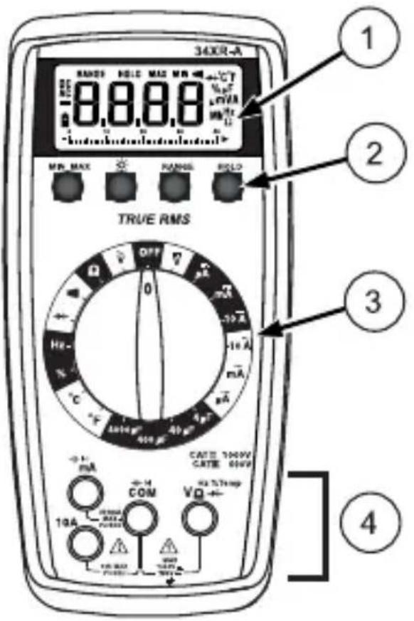
- Display Afficheur Anzeige Display Pantalla Scherm
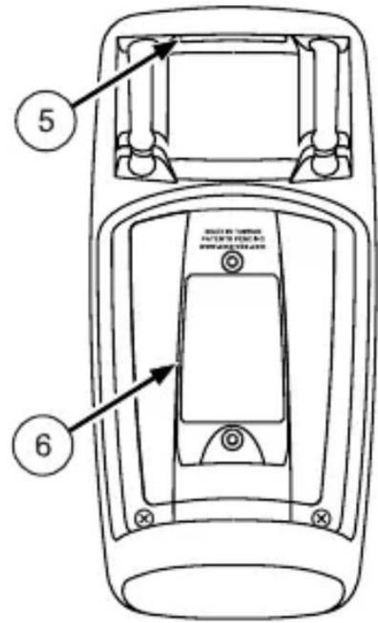
- Strap Clip
Clip de bretelle
Klemme
Clip in velocro
Clip para correa
Riemclip - Feature Buttons Boutons de fonctions Funktionstasten Pulsanti delle funzioni Botones de referencia Functieknoppen
- Battery/Fuse Cover Capot des fusibles/pile Batterie-/Sicherungsabdeckung Sportello del vano portapile/fusibili Puerta de la bateria y el fusible Deksel van batterij en zekering
- Function/Range Switch Commutateur de gamme/fonction Funktion/Bereich-Schalter Selettore funzione/portata Selector de la direccion y del rango Functie- en bereikschakelaar
- Test Lead Connections Branchements des cordons de test Messleitungsanschlusse Boccole per i cavetti Conexiones de los conductores de prueba Aansluitingen voor testkabels
SAFETY INFORMATION 1
INTRODUCTION 2
MAKING MEASUREMENTS 2
Verify Instrument Operation 2
Range Selection 2
Correcting an Overload (OL) Indication 2
Measuring DC Voltage .See Figure -1- 2
Measuring AC Voltage (True rms) See Figures -2- & -3- 3
Preparing for Current Measurements 3
Measuring DC Current . See Figure -4- 3
Measuring AC Current (True rms) See Figures -3- & -5- 3
Measuring Resistance . See Figure -6- 4
Measuring Continuity. See Figure -7- 4
Checking Diodes .See Figure -8- 4
Measuring Capacitance . See Figure -9- 4
Measuring Temperature . See Figure -10- 4
Measuring Frequency . See Figure -11- 5
Measuring Dutycycle .See Figure -12- 5
ADDITIONAL FEATURES 5
Input Test Lead Warning 5
True-rms Measurements 5
MIN MAX Measurements 5
Auto Power Off 6
HOLD Measurements 6
Backlight 6
PRODUCT MAINTENANCE 6
Battery and Fuse Replacement....See Figure -13- 7
SPECIFICATIONS 7
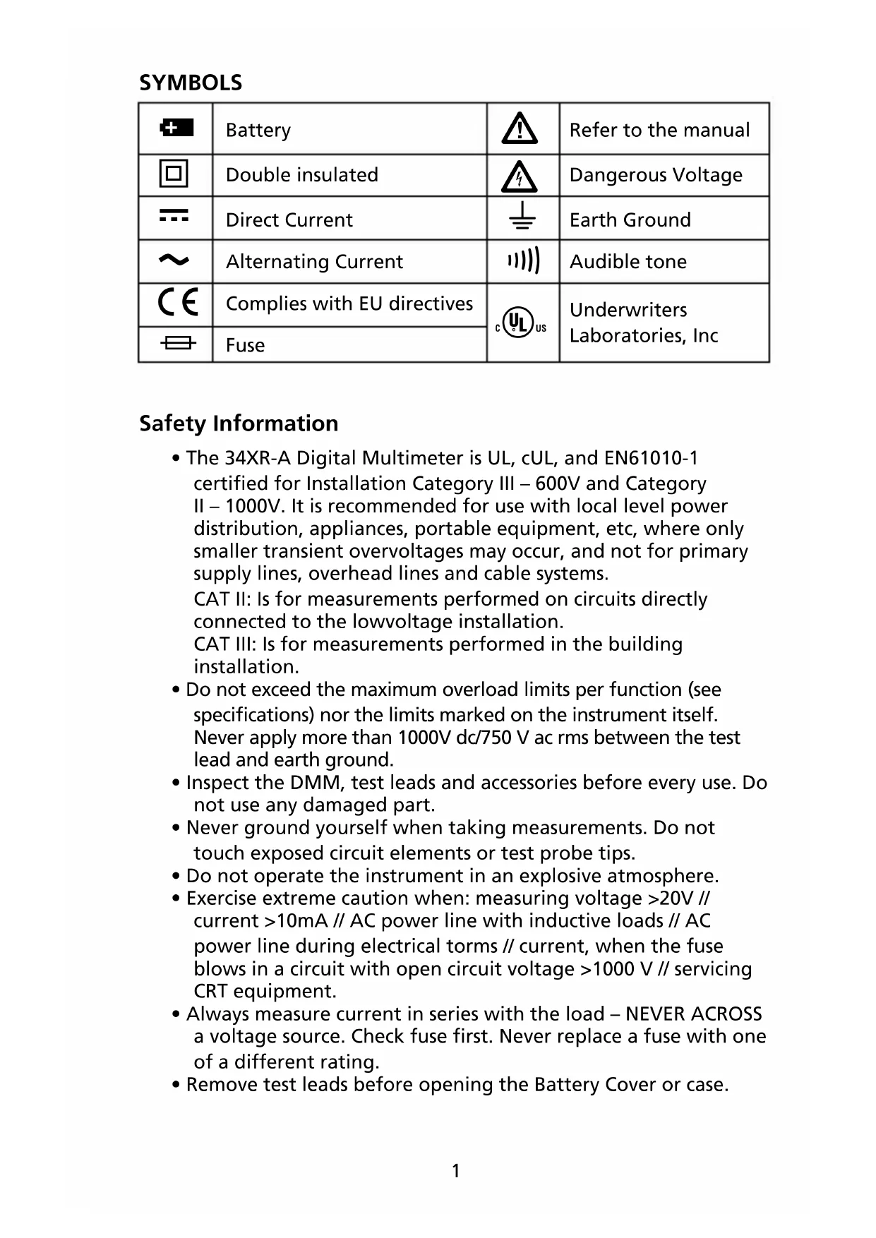
SYMBOLS
| + | Battery | △ | Refer to the manual |
| □ | Double insulated | △ | Dangerous Voltage |
| — | Direct Current | ⊥ | Earth Ground |
| ~ | Alternating Current | ||||| | Audible tone |
| CE | Complies with EU directives | cULUS | Underwriters Laboratories, Inc |
| = | Fuse |
Safety Information
- The 34XR-A Digital Multimeter is UL, cUL, and EN61010-1 certified for Installation Category III - 600V and Category II - 1000V. It is recommended for use with local level power distribution, appliances, portable equipment, etc, where only smaller transient overvoltages may occur, and not for primary supply lines, overhead lines and cable systems.
CAT II: Is for measurements performed on circuits directly connected to the lowvoltage installation.
CAT III: Is for measurements performed in the building installation. - Do not exceed the maximum overload limits per function (see specifications) nor the limits marked on the instrument itself. Never apply more than 1000V dc/750 V ac rms between the test lead and earth ground.
- Inspect the DMM, test leads and accessories before every use. Do not use any damaged part.
- Never ground yourself when taking measurements. Do not touch exposed circuit elements or test probe tips.
- Do not operate the instrument in an explosive atmosphere.
- Exercise extreme caution when: measuring voltage >20V // current >10mA // AC power line with inductive loads // AC power line during electrical terms // current, when the fuse blows in a circuit with open circuit voltage >1000V // servicing CRT equipment.
- Always measure current in series with the load - NEVER ACROSS a voltage source. Check fuse first. Never replace a fuse with one of a different rating.
- Remove test leads before opening the Battery Cover or case.
The 34XR-A is a True rms autoranging handheld digital multimeter for measuring or testing the following:
- DC and AC voltage - Temperature - Resistance
- DC and AC current
- Capacitance
- Diodes
- Frequency - Continuity - Dutycycle
Additional features include: MIN MAX, HOLD, Backlight, and Range Lock
MAKING MEASUREMENTS
Verify Instrument Operation
Before attempting to make a measurement, verify that the instrument is operational and the battery is good. If the instrument is not operational, have it repaired before attempting to make a measurement.
Range Selection
In addition to autoranging the 34XR-A allows you to manually select and lock a range by pressing the RANGE button. RANGE appears on the display to indicate that manual ranging is active. Each subsequent press of the range button steps the meter to the next higher range. When the highest range is reached the next press returns the meter to the lowest range. To return to autoranging press and hold the RANGE button for 2 seconds. RANGE no longer shows on the display. Use autorange for all initial measurements. Then, when appropriate, use the RANGE button to select and lock a range.
Warning: To avoid electrical shock while manual ranging use the display annunciators to identify the actual range selected.
Correcting an Overload (OL or -OL) Indication
An OL indication may appear on the display to indicate that an overload condition exists. For voltage and current measurements, an overload should be immediately corrected by selecting a higher range. If the highest range setting does not eliminate the overload, interrupt the measurement until the problem is identified and eliminated. The OL indication is normal for some functions; for example, resistance, continuity, and diode test.
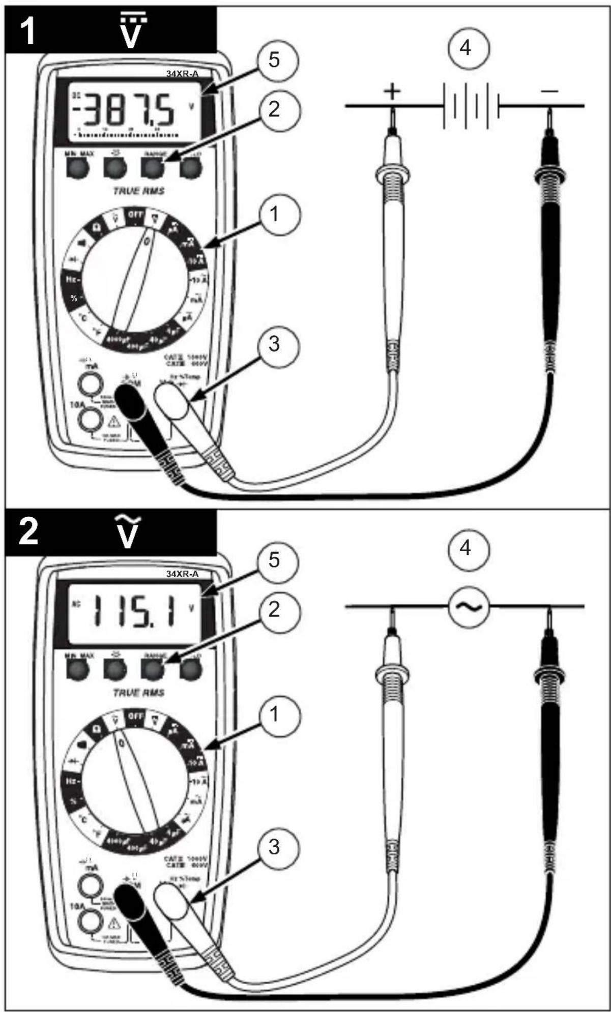
Measuring DC Voltage See Figure -1-
- Set the Function Switch to .
- If RANGE is displayed, press the RANGE button to enable autoranging.
- Connect the Test Leads: Red to V , Black to COM
- Connect the Test Probes to the circuit test points.
- Read the display, and, if necessary, correct any overload (OL) conditions.
Measuring AC Voltage (True rms) See Figures -2- & -3- See Additional Features to find out the advantages of true rms.
- Set the Function Switch to .
- If RANGE is displayed, press the RANGE button to enable autoranging.
- Connect the Test Leads: Red to V , Black to COM
- Connect the Test Probes to the circuit test points
- Read the display, and, if necessary, correct any overload (OL) conditions.
Preparing for Current Measurements
- Turn off circuit power before connecting the test probes.
- Allow the meter to cool between measurements if current measurements approach or exceeds 10 amps.
- A warning tone sounds if you connect a test lead to a current input before you select a current range.
- Open circuit voltage at the measurement point must not exceed 1000V .
- Always measure current in series with the load. Never measure current across a voltage source.
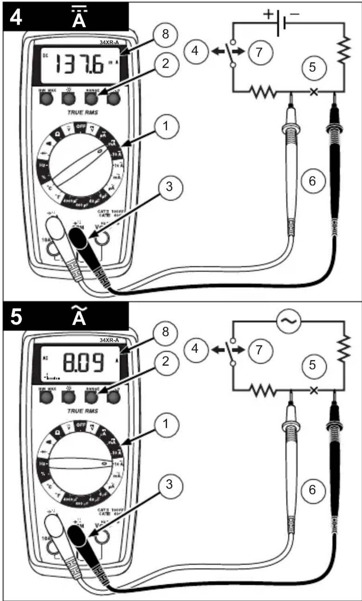
Measuring DC Current See Figure -4-
- Set the Function Switch to a function and range.
- If RANGE is displayed, press the RANGE button to enable autoranging.
- Connect the Test Leads: Red to A mA or 10A, Black to COM
- Turn off power to the circuit being measured.
- Open the test circuit (一 × 一) to establish measurement points.
- Connect the Test Probes in series with the load.
- Turn on power to the circuit being measured.
- Read the display, and, if necessary, correct any overload (OL) conditions.
Measuring AC Current (True rms) See Figures -3- & -5- See Additional Features to find out the advantages of true rms.
- Set the Function Switch to a function and range.
- If RANGE is displayed, press the RANGE button to enable autoranging.
- Connect the Test Leads: Red to A mA or 10A, Black to COM
- Turn off power to the circuit being measured.
- Open the test circuit (—X) to establish measurement points.
- Connect the Test Probes in series with the load.
- Turn on power to the circuit being measured.
- Read the display, and, if necessary, correct any overload (OL) conditions.
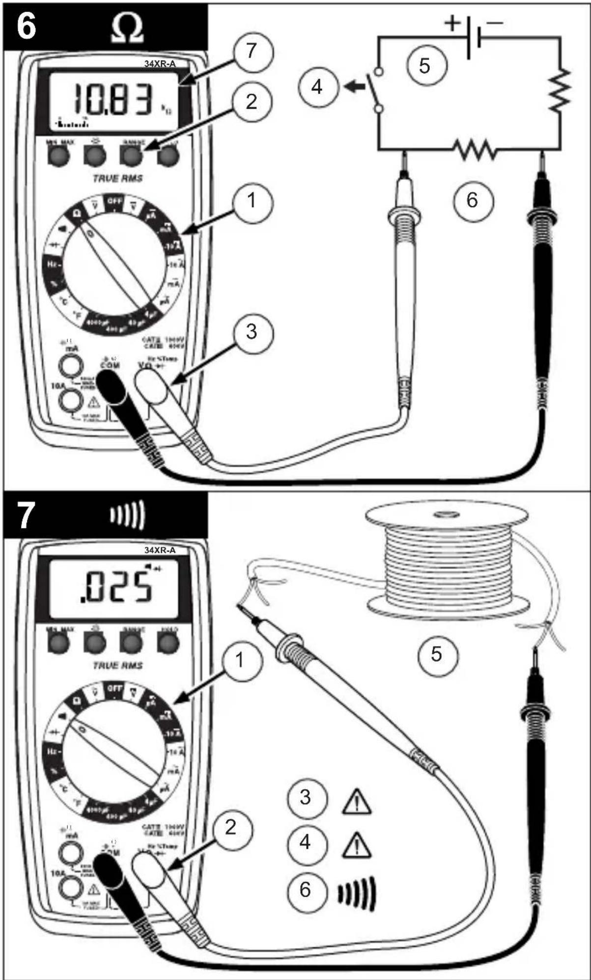
Measuring Resistance See Figure -6-
- Set the Function Switch to .
- If RANGE is displayed, press the RANGE button to enable autoranging.
- Connect the Test Leads: Red to VΩ→, Black to COM
- Turn off power to the circuit being measured. Never measure resistance across a voltage source or on a powered circuit.
- Discharge any capacitors that may influence the reading.
- Connect the Test Probes across the resistance.
- Read the display. If OL appears on the highest range, the resistance is too large to be measured.
Measuring Continuity See Figure -7-
- Set the Function Switch to ^(1) .
- Connect the Test Leads: Red to VΩ→, Black to COM
- Turn off power to the circuit being measured.
- Discharge any capacitors that may influence the reading.
- Connect the Test Probes across the resistance.
- Listen for the tone that indicates continuity (< 35) .
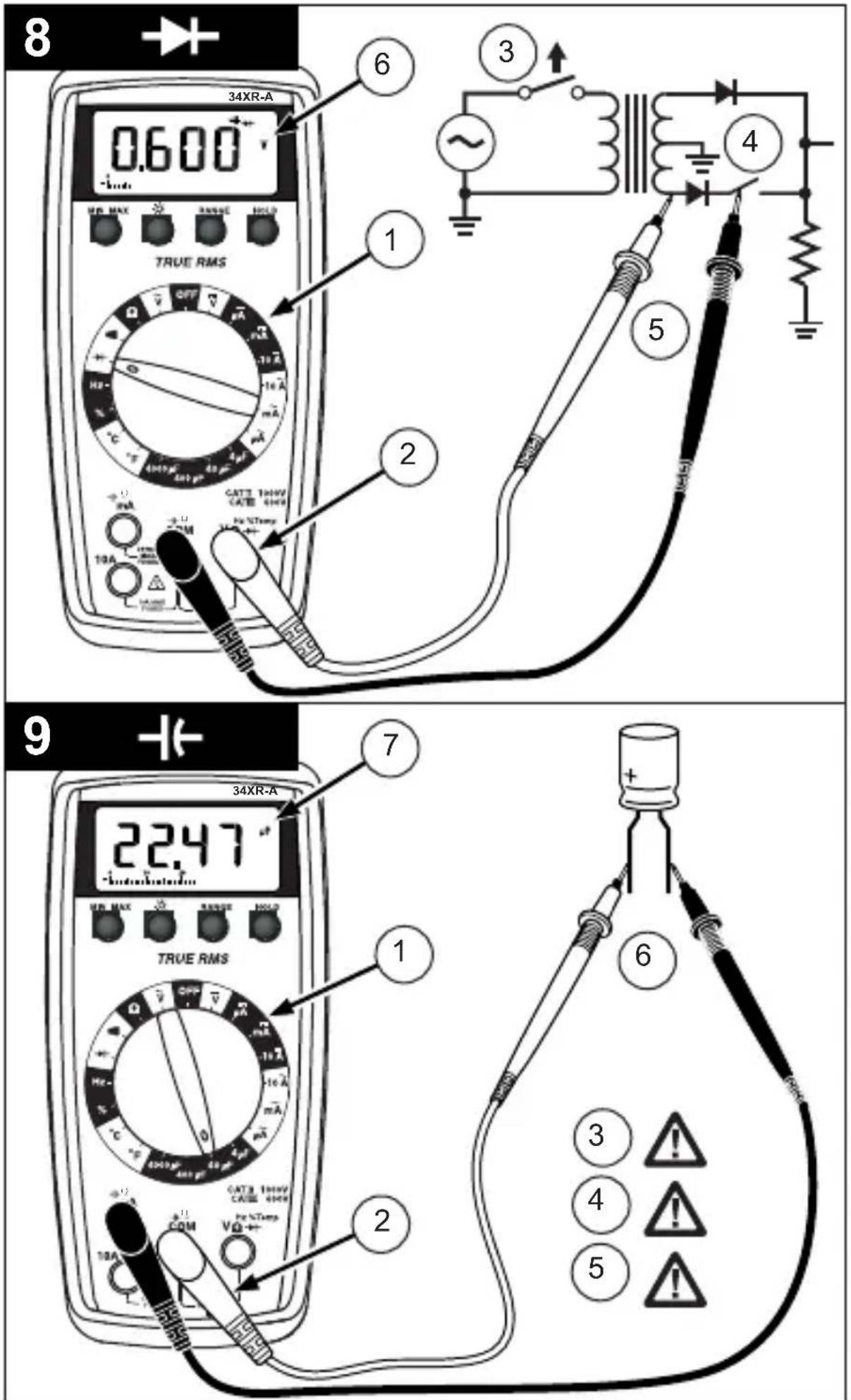
Checking Diodes See Figure -8-
- Set the Function Switch to .
- Connect the Test Leads: Red to V , Black to COM
- Turn off power to the circuit being measured.
- Free at least one end of the diode from the circuit.
- Connect the Test Probes across the diode.
- Read the display. A good diode has a forward voltage drop of about 0.6V . An open or reverse biased diode will read OL.
Measuring Capacitance See Figure -9-
- Set the Function Switch to an appropriate F function and range.
- Connect the Test Leads: Red to COM, Black to A mA-(-).
- Turn off power to the circuit being measured.
- Discharge the capacitor using a 100k resistor.
- Free at least one end of the capacitor from the circuit.
- Connect the Test Probes across the capacitor. When measuring an electrolytic capacitor match the test lead polarity to the polarity of the capacitor.
- Read the display.
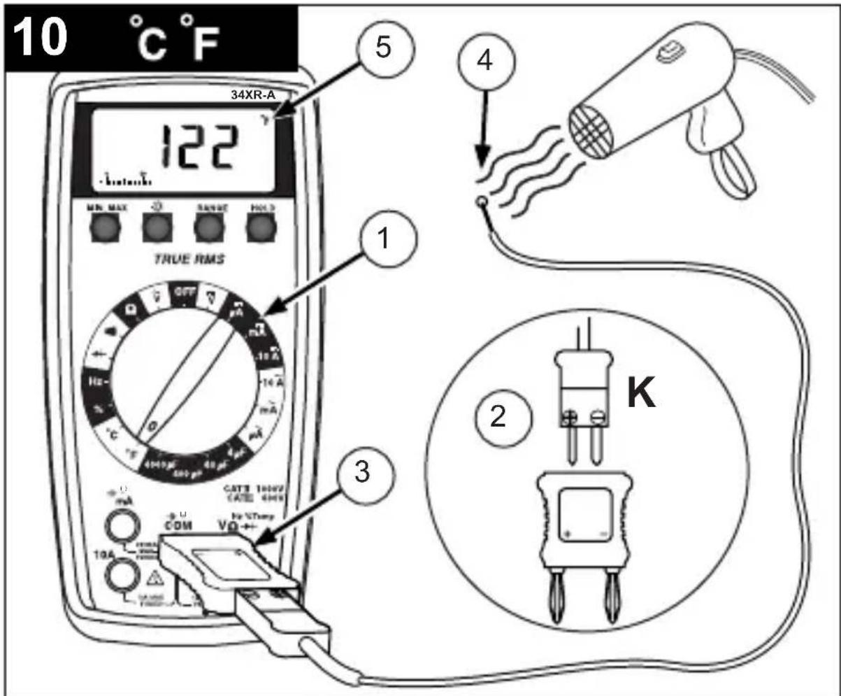
Measuring Temperature See Figure -10-
- Set the Function Switch to ^ C or ^
- Connect the K-type thermocouple to a TEMP adapter (XR-TA). Match the polarity of the adapter to the polarity of the thermocouple.
- Connect the TEMP adapter to the V + and COM inputs. Note: The 34XR-A is compatible with all K-type thermocouples.
The K -type bead thermocouple supplied with the meter is not intended for contact with liquids or electrical circuits.
- Expose the thermocouple to the temperature to be measured.
- Read the display.
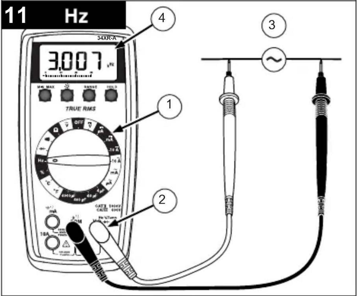
Measuring Frequency See Figure -11-
- Set the Function Switch to Hz.
- Connect the Test Leads: Red to Hz, Black to COM
- Connect the Test Probes to the signal source.
- Read the display. The Meter will autorange for the best resolution.
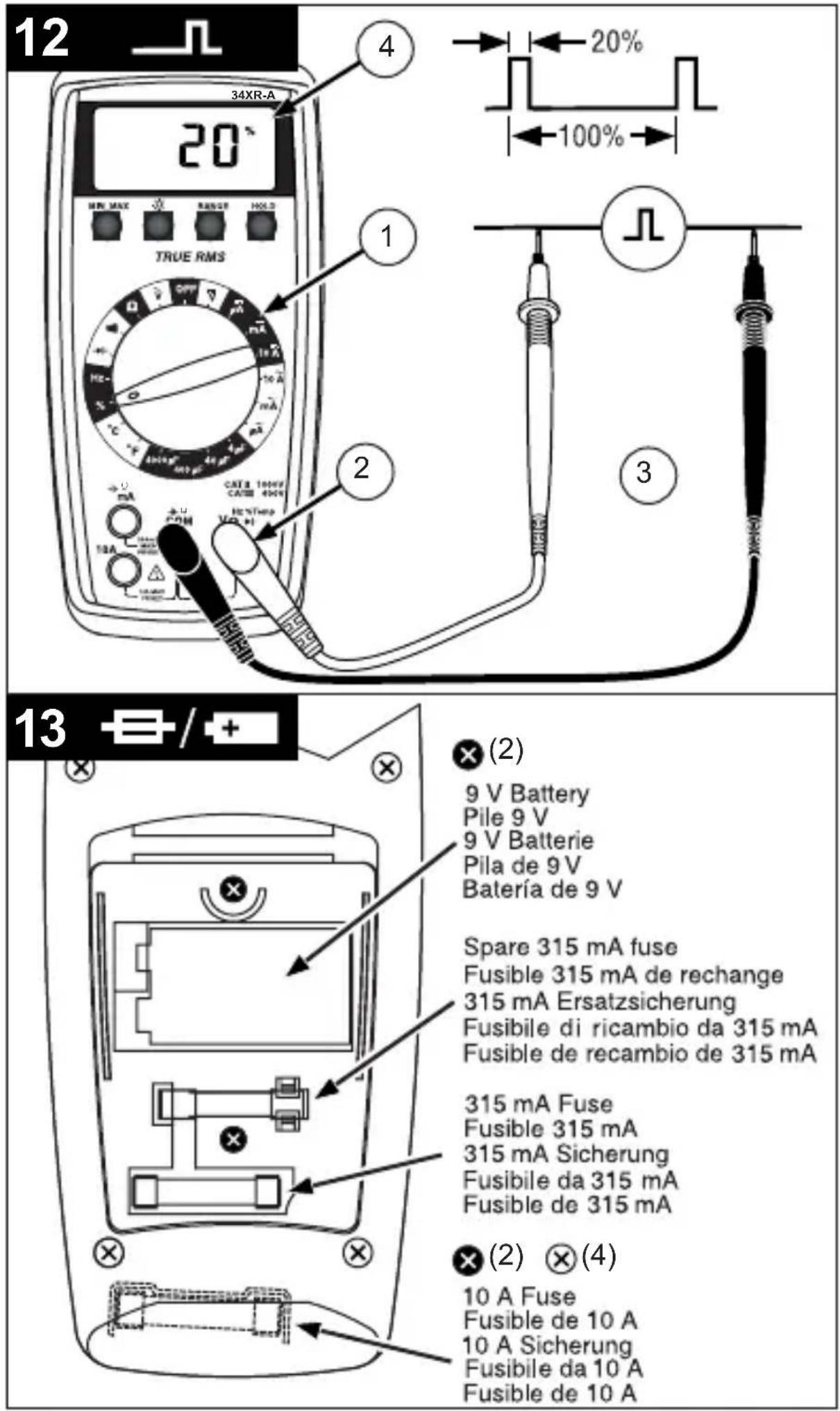
Measuring Dutycycle See Figure -12-
- Set the Function Switch to %.
- Connect the Test Leads: Red to %, Black to COM
- Connect the Test Probes to the signal source.
- Read the display. The Meter will autorange for the best resolution.
ADDITIONAL FEATURES
Input Test Lead Warning
The meter emits a continuous tone when a test lead is placed in the A mA or 10A input jack and the Function/Range Switch is not set to a correct current position. (If the meter is connected to a voltage source with leads connected for current, very high current could result). All current ranges are protected by fast acting fuses.
True-rms Measurements
For ac measurements most DMMs average the ac input signal and display the result as an estimated rms value. This average-responding method is accurate for sinusoidal waveforms, but can be very inaccurate for distorted waveforms. To ensure the most accurate measurements, always use a true-rms DMM when measuring ac voltage or ac current on circuits for the following kinds of applications:
- Power Supplies - diodes - Controllers
- Power Limiting - SCR or Triac - Starting - motors
- Florescent Lighting
- ballasts
- Speed Control
- motors
- Any non-sinusoidal ac waveform - Pulsed Signals
MIN MAX Measurements
The MIN MAX function reads and updates the display to show the maximum or minimum value measured after you press the MIN MAX button. Pressing the MIN MAX button for less than 1 second will put the meter into a mode of displaying the maximum, minimum, or actual readings. Each time the button is pressed, the meter will cycle to the next display mode as shown in the table below. Press the MIN MAX button for more than 2 seconds to exit MIN MAX.
| Button Display Value Displayed | ||
| < 1 second M | AX Maximum | value after feature activated |
| < 1 second M | N Minimum | value after feature activated |
| < 1 second M | N MAX (blinks) | Normal measurement, actual reading |
| >2 seconds Exit MIN MAX | Normal measurement, actual reading | |
Auto Power Off
Auto Power Off is a battery saving feature that puts the meter into a sleep mode if the Function/Range Switch has not changed position in the last 30 minutes. To wake the meter turn it off and then on.
The Auto Power Off feature can be disabled to keep the meter from going to sleep. This feature is useful when using the MIN MAX mode for extended periods. To disable the Auto Power Off feature use the following procedure:
- Set the Function Switch to OFF.
- Press and hold the MIN MAX button while turning the Function Switch to the desired function.
- Continue to press the MIN MAX button until the display finishes this initialization period and the reading settles.
- Release the MIN MAX button. The Auto Power Off feature will remain disabled until the meter is turned off and then on.
HOLD Measurements
The HOLD button causes the meter to capture and continuously display a measurement reading. To use the HOLD feature make a measurement, and then, after the reading has stabilized, momentarily press the HOLD button. You can remove the test leads and the reading will remain on the display. Pressing the HOLD button again releases the display.
Backlight
Pressing the button illuminates the display with a blue backlight.
The backlight will automatically turn off in about 60 seconds.
Frequent use of the backlight will decrease battery life.
PRODUCT MAINTENANCE
Cleaning
To clean the meter, use a soft cloth moistened with water. To avoid damage to the plastic components do not use benzene, alcohol, acetone, ether, paint thinner, lacquer thinner, ketone or other solvents to clean the meter.
Troubleshooting
If the meter appears to operate improperly, check the following items first.
- Review the operating instructions to ensure the meter is being used properly.
- Inspect and test the continuity of the test leads.
- Make sure the battery is in good condition. The low battery symbol + appears when the battery falls below the level where accuracy is guaranteed. Replace a low-battery immediately.
- Check the condition of the fuses if the current ranges operate incorrectly.
Battery and Fuse Replacement See Figure -13-
Warning: To avoid electrical shock remove the test leads from both the meter and the test circuit before accessing the battery or the fuses.
To access the battery and the mA fuse remove the two screws holding the Battery/Fuse Cover in place, and lift the cover from the meter. To replace the mA fuse, pry it from its clips using a small screwdriver. A spare mA fuse is located between the battery and the mA fuse.
mA Fuse: Fast Blow 315mA/1000V, minimum interrupt rating 30 kA (6.3 x 32 mm) (Amprobe® FP300)
To replace the 10 A fuse: 1) Remove the battery. 2) Remove the four rear-case screws. 3) Separate the case. 4) Remove the 10 A fuse cover. 5) Remove and replace the 10A fuse. 6) Re-install the fuse cover. 7) Reassemble the meter.
10A Fuse: Fast Blow 10A/1000V, minimum interrupt rating 30kA (10 x 38 mm) (Amprobe® FP100).
SPECIFICATIONS
General Specifications
| Display | 3 ¼ digit liquid crystal display (LCD)(3999 count) with a 41-segment |
| Polarity | Automatic, positive implied, negative polarity indication. |
| Overrange (OL) or (-OL) is displayed. | |
| Zero Automatic. | |
| Low battery indication | The ↑ is displayed when the battery voltage drops below the operating level. |
| Auto power off Approx. 30 minutes. | |
| Measurement rate 2 times per second, nominal. | |
| Operating environment | 0 °C to 50 °C at <70 % R.H. for all functions except 10A range. 10A range: 0 °C to 40 °C at < 70 % R.H. |
| Storage temperature | -20 °C to 60 °C, 0 to 80 % R.H. with battery removed from meter. |
| Temperature Coefficient | 0.1 × (specified accuracy) per °C. (0 °C to 18 °C, 28 °C to 50 °C). |
| Altitude 2000 m (6562 feet) | |
| Power | Single standard 9-volt battery, NEDA 1604, JIS 006P, IEC 6F22. |
| Battery life | 100 hours typical with carbon-zinc. 200 hours typical with alkaline. Frequent use of the backlight will decrease battery life. |
| Dimensions 196 mm (H) × | 92 mm (W) × 60 mm (D). |
| Weight Approximately 40 g including battery. | |
| Box contents | The 34XR-A includes the following items: Test leads w/ alligator clips 1 set Holster 1 Magnet Strap 1 Temperature Adapter 1 K-type thermocouple 1 Users Manual 1 9 V battery (installed) 1 mA fuse, 0.315 A/ 1000 V 1 spare |
Approvals:


Safety: Conforms to UL61010-1; EN61010-1:2010; EN61010-2-033:2012 Cat II - 1000V / Cat III - 600V; Class 2, Pollution degree II.
CAT II : Is for measurements performed on circuits directly connected to the lowvoltage installation.
CAT III : Is for measurements performed in the building installation.
EMC: Conforms to EN61326-1, This product complies with requirements of the following European Community Directives: 89/336/EEC (Electromagnetic Compatibility) and 73/23/EEC
(Low Voltage) as amended by 93/68/EEC (CE Marking). However, electrical noise or intense electromagnetic fields in the vicinity of the equipment may disturb the measurement circuit. Measuring
instruments will also respond to unwanted signals that may be present within the measurement circuit. Users should exercise care and take appropriate precautions to avoid misleading results when making measurements in the presence of electronic interference.
ELECTRICAL SPECIFICATIONS
(Accuracy at 23^± 5^, < 75% relative humidity)
DC VOLTS
| Ranges 400mV, 4V, 40V, | 400V, 1000V |
| Resolution 100 μV in 400 | mV range |
| Accuracy ±(0.5 % rdg + 1 | dgt) |
| Input impedance | 400mV: >100 MΩ; 4V: 10 MΩ; 40V to 1000V: 9.1 MΩ |
| Overload protection 100 | 0 V dc / 750 Vac rms |
AC Volts true rms (45Hz - 2kHz)
| Ranges 400m, 4V, 40V, 400V, 750V | |
| Resolution 100 μV | |
| Accuracy | ±(1.2 % rdg +8 dgts) 45 Hz to 100 Hz on 400mV range ±(1.2 % rdg + 8 dgts) 45 Hz to 500 Hz ±(2.0 % rdg +8 dgts) 500 Hz to 2 kHz ±(2.0 % rdg + 8 dgts) 45 Hz to 1 kHz on 750 V range |
| Crest Factor ≤ 3 | |
| Input impedance | 400mV: >100 MΩ; 4V: 10 MΩ; 40V to 1000V: 9.1 MΩ AC coupled true rms specified from 10 % to 100 % of range |
| Overload protection 100 V dc or 750 V ac rms | |
DC Current
| Ranges 400μA, 4000μA, | 40mA, 300mA, 10A |
| Resolution 0.1μA | |
| Accuracy | ±(1.0 % rdg + 1 dgt) on 400μA to 300mA ranges ±(2.0 % rdg + 3 dgts) on 10A range. |
| Burden voltage | 400 μA Range: 1 mV/ 1 μA 4 mA Range: 500 mV/ 1 mA 40 mA Range: 10 mV/ 1 mA 300 mA: 8 mV/ 1 mA 10A: 40 mV/ 1 A |
| Input protection | 0.315A/1000V fast blow ceramic fuse 6.3×32mm on μA/mA input 10A/1000V fast blow ceramic fuse 10×38mm on 10A input 10A input: 10 A for 5 minutes maximum followed by a 10 minute cooling period |
AC Current true rms (45Hz - 1kHz)
| Ranges 400μA, 4000μA, | 40mA, 300mA, 10A |
| Resolution 0.1μA | |
| Accuracy | ±(1.5 % rdg + 8 dgts) on 400μA to 300mA ranges ±(2.5 % rdg + 10 dgts) on 10A range |
| Crest Factor ≤ 3 | |
| Burden voltage See DC Current | |
| Input protection | 0.315A/1000V fast blow ceramic fuse 6.3×32mm on μA/mA input 10A/1000V fast blow ceramic fuse 10×38mm on 10A input 10A input: 10 A for 4 minutes maximum followed by a 12 minute cooling period |
Resistance
| Ranges | 400Ω, 4kΩ, 40kΩ, 400kΩ, 4MΩ, 40MΩ |
| Resolution 100 mΩ | |
| Accuracy | ±(1.0 % rdg + 4 dgts) on 400Ω to 4MΩ ranges ±(2.0 % rdg + 5 dgts) on 40MΩ range |
| Open circuit volts | -0.45 V dc typical, (-1.2 V dc on 400Ω range) |
| Overload protection 100 | 0 V dc or 750 V ac rms |
Capacitance
| Ranges 4μF, 40μF, 400μF, 4000μF | |
| Resolution 1 nF | |
| Accuracy | ±(5.0 % rdg + 10 dgts) on 4μF range ±(5.0 % rdg + 5 dgts) on 40μF to 400μF ranges ±(5.0 % rdg + 15 dgts) on 4000μF range |
| Test voltage < 3.0 V | |
| Test Frequency 25Hz | |
| Input protection | 0.315A/1000V fast blow ceramic fuse 6.3×32mm on μA/mA input |
Temperature
| Ranges -20 °C to 1000 °C, -4 °F to 1832 °F | |
| Resolution 1 °C, 1 °F | |
| Accuracy | ±(2.0 % rdg + 4 °C) -20 °C to 10 °C ±(1.0 % rdg + 3 °C) 10 °C to 200 °C ±(3.0 % rdg + 2 °C) 200 °C to 1000 °C ±(2.0 % rdg + 8 °F) -4 °F to 50 °F ±(1.0 % rdg + 6 °F) 50 °F to 400 °F ±(3.0 % rdg + 4 °F) 400 °F to 1832 °F |
| Overload protection 100 V dc or 750 V ac rms | |
Frequency
| Ranges 4k, 40k, 400k, 1MHz |
| Resolution 1 Hz |
| Accuracy ±(0.1 % rdg + 3 dgts) |
| Sensitivity 10 Hz to 1 MHz: >2.5 V ac rms; |
| Minimum pulse width > 1 μs |
| Duty cycle limits > 30 % and < 70 % |
| Overload protection 100 0 V dc or 750 V ac rms |
Duty Cycle
| Ranges 0 to 90 % | |
| Resolution 0.1 % | |
| Pulse width >10 μs | |
| Frequency range 40 Hz to 20 kHz | |
| Accuracy (5V logic) ±(2.0% rdg + 5 dgts) | |
| Overload protection 1000 V dc or 750 V ac rms | |
Continuity
| Audible indication < 35 Ω |
| Response time 100 ms |
| Overload protection 1000 V dc or 750 V ac rms |
Diode Test
| Test current approximately 1.2 mA |
| Accuracy ±(1.5 % rdg + 3 dgts) |
| Resolution 1 mV |
| Open circuit volts 3.0 V dc typical |
| Overload protection 1000 V dc or 750 V ac rms |
Additional Features
| μA mA, 10A Test Lead Connection | Beeps to warn test leads are connected to measure current while Function/ Range Switch is not set to a measure current. |
| MIN MAX | Displays the minimum or maximum value detected while making a measurement. |
| HOLD Holds the latest reading on the display. | |
| RANGE Manual range mode. | |
| Backlight | Backlight auto-off approximately 60 seconds |
| Auto Power off 30 minutes, typical | |
Replacement Parts
TL36 Test Lead Set with Alligator clips
FP300 mA fuse - Fuse Pack .315A/1000V (4 each)
FP100 10A fuse - Fuse Pack 10A/1000V (2 each)
XR-TA Input Adapter for K-type thermocouple
TP255 K type thermocouple
XR-H2 Magne-Grip® Holster, clip, magnet, and strap
| 3 True rms | 34XR-A AC True rms * | |
| Input Waveform Signal d'entrée Eingangsschwingungsform Forma d'onda d'ingresso Forma de onda de entrada | ||
| Sine Wave Sinusoidale Sinusschwingung Onda sinusoidale Onda sinusoidal | +Vpeak 0 -Vpeak | .707 x Vpeak CF = 1.414 |
| Full Wave, Sine Wave Onde complete, Sinusoidale Volle Schwingung, Sinusschwingung Onda sinusoidale, onda intera Onda completa, Onda sinusoidal | Vpeak 0 | 0.308 x Vpeak CF = 3.247 |
| Half-Wave, Sine Wave Demi-onde, sinusoidale Halbschwingung, Sinusschwingung Onda sinusoidale, semionda Media onda, onda sinusoidal | Vpeak 0 | 0.386 x Vpeak CF = 2.591 |
| Square Wave Onde carrée Rechteckschwingung Onda quadra Onda cuadrada | +Vpeak 0 -Vpeak T0 | T1 T0 = T1 | 1.000 x Vpeak CF = 1.000 |
| Square Wave Onde carrée Rechteckschwingung Onda quadra Onda cuadrada | Vpeak 0 -T0 | T1 T0 = T1 | 0.500 x Vpeak CF = 2.000 |
| Pulse Wave Onde impulsionnelle Impulsschwingung Onda dell'impulso Onda de impulsos | Vpeak 0 b c D = b/c K = √D-D² | Vpeak x K CF = 1 / K |
| Sawtooth Wave Onde en dent de scie Sägezahnschwingung Onda a denti di sega Onda diente de sierra | +Vpeak 0 -Vpeak | 0.577 x Vpeak CF = 1.733 |
| * CF = Crest Factor, Crest Factor = Vpeak / Vrms | ||
AMPROBE
34XR-A
Amprobe Test Tools Amprobe Test Tools
Everett, WA 98203 Mississauga, Ontario L4Z 1X9
Tel: 888-993-5853 Tel: 905-890-7600
Fax: 425-446-6390 Fax: 905-890-6866
Amprobe Test Tools Amprobe Test Tools
Everett, WA 98203 Mississauga, ON L4Z 1X9
Tel.: 888-993-5853 Tel.: 905-890-7600
Fax: 425-446-6390 Fax: 905-890-6866
SYMBOLE IN DIESEM HANDBUCH
Amprobe Test Tools Amprobe Test Tools
Everett, WA 98203 Mississauga, ON L4Z 1X9
Tel: 888-993-5853 Tel: 905-890-7600
Fax: 425-446-6390 Fax: 905-890-6866
Amprobe Test Tools Amprobe Test Tools
Everett, WA 98203 Mississauga, ON L4Z 1X9
Tel: 888-993-5853 Tel: 905-890-7600
Fax: 425-446-6390 Fax: 905-890-6866
Amprobe Test Tools Amprobe Test Tools
Everett, WA 98203 Mississauga, ON L4Z 1X9
Tel: 888-993-5853 Tel: 905-890-7600
Fax: 425-446-6390 Fax: 905-890-6866
TP255 K-type thermokoppel
XR-H2 Magne-Grip®-holster, clip, magneet en riem
Visit www.Amprobe.com for
- Catalog
Application notes - Product specifications
- User manuals