
PRM6 - Multimeter Amprobe - Free user manual and instructions
Find the device manual for free PRM6 Amprobe in PDF.
| Product type | Phase and motor rotation tester |
| Brand | Amprobe |
| Model | PRM-6 |
| Dimensions (H x W x D) | 137 x 65 x 33 mm |
| Weight | 170 g (with batteries) |
| Power supply | 2 AAA 1.5 V alkaline batteries |
| Battery life | At least 2 years for normal use |
| Display | LCD with backlight |
| Input voltage range (phase to phase) | 40…700 V AC (16…60 Hz) / 50…700 V AC (>60…400 Hz) |
| Frequency range | 16…400 Hz |
| Rated test current (per phase) | ≤ 3.5 mA |
| Phase rotation indication | Clockwise / counterclockwise via LCD |
| Contactless motor rotation indication | Yes, via LCD |
| Motor connection determination | Yes, with manual shaft rotation |
| Faulty input voltage detection | Difference > ±30 % phase-phase or > ±65 % phase-neutral |
| Overvoltage category | CAT IV 600 V |
| Protection rating | IP 40 |
| Pollution degree | 2 |
| Operating temperature | 0 °C to 40 °C |
| Humidity (non-condensing) | ≤ 80 % RH |
| Operating altitude | Up to 2,000 m |
| Safety standards | EN 61010-1, EN 61557-1/-7, UL 61010-1, CAN/CSA C22.2 No. 61010-1-12 |
| Electromagnetic compatibility | EN 61326-1 |
| Supplied accessories | 3 test cables (black, red, yellow), 3 test probes, 3 alligator clips, 2 AAA batteries, carrying case, user guide |
| Maintenance | Clean with a soft cloth and a neutral solution of water and detergent |
| Battery replacement | Disconnect probes, open compartment with a flathead screwdriver, observe polarities |
| Warranty | 1 year (excluding batteries, fuses, accidental damage) |
Frequently Asked Questions - PRM6 Amprobe
User questions about PRM6 Amprobe
0 question about this device. Answer the ones you know or ask your own.
Ask a new question about this device
Download the instructions for your Multimeter in PDF format for free! Find your manual PRM6 - Amprobe and take your electronic device back in hand. On this page are published all the documents necessary for the use of your device. PRM6 by Amprobe.
USER MANUAL PRM6 Amprobe
Motor and Phase Rotation Tester
User Manual
Motor and Phase Rotation Tester
Users Manual

Limited Warranty and Limitation of Liability
Your Amprobe product will be free from defects in material and workmanship for one year from the date of purchase unless local laws require otherwise. This warranty does not cover fuses, disposable batteries or damage from accident, neglect, misuse, alteration, contamination, or abnormal conditions of operation or handling. Resellers are not authorized to extend any other warranty on the behalf of Amprobe. To obtain service during the warranty period, return the product with proof of purchase to an authorized Amprobe Service Center or to an Amprobe dealer or distributor. See Repair Section for details. THIS WARRANTY IS YOUR ONLY REMEDY. ALL OTHER WARRANTYES - WHETHER EXPRESS, IMPLIED OR STATUTORY - INCLUDING IMPLIED WARRANTY OF FITNESS FOR A PARTICULAR PURPOSE OR MERCHANTABILITY, ARE HEREBY DISCLAIMED. MANUFACTURER SHALL NOT BE LIABLE FOR ANY SPECIAL, INDIRECT, INCIDENTAL OR CONSEQUENTIAL DAMAGES OR LOSSES, ARISING FROM ANY CAUSE OR THEORY. Since some states or countries do not allow the exclusion or limitation of an implied warranty or of incidental or consequential damages, this limitation of liability may not apply to you.
Repair
All Amprobe returned for warranty or non-warranty repair or for calibration should be accompanied by the following: your name, company's name, address, telephone number, and proof of purchase. Additionally, please include a brief description of the problem or the service requested and include the test leads with the meter. Non-warranty repair or replacement charges should be remitted in the form of a check, a money order, credit card with expiration date, or a purchase order made payable to Amprobe.
In-warranty Repairs and Replacement – All Countries
Please read the warranty statement and check your battery before requesting repair. During the warranty period, any defective test tool can be returned to your Amprobe distributor for an exchange for the same or like product. Please check the "Where to Buy" section on www.Amprobe.com for a list of distributors near you. Additionally, in the United States and Canada, in-warranty repair and replacement units can also be sent to an Amprobe Service Center (see address below).
Non-warranty Repairs and Replacement – United States and Canada
Non-warranty repairs in the United States and Canada should be sent to an Amprobe Service Center. Call Amprobe or inquire at your point of purchase for current repair and replacement rates.
USA: Canada:
Amprobe
Amprobe
Everett, WA 98203 Mississauga, ON L4Z 1X9
Tel: 877-AMPROBE (267-7623) Tel: 905-890-7600
Non-warranty Repairs and Replacement – Europe
European non-warranty units can be replaced by your Amprobe distributor for a nominal charge. Please check the "Where to Buy" section on www.Beha-Amprobe.com for a list of distributors near you.
Amprobe Europe*
Beha-Amprobe
In den Engematten 14
79286 Glottertal, Germany
Tel.: +49 (0) 7684 8009 - 0
www.Beha-Amprobe.com
*Correspondence only - no repair or replacement available from this address. European customers please contact your distributor.)
CONTENTS
SYMBOL 3
SAFETY INFORMATION 3
UNPACKING AND INSPECTION 5
USING PHASE SEQUENCE & MOTOR ROTARY TESTER 5
Determine the Rotary Field Direction 5
Non-Contact Rotary Field Indication 6
Determine the Motor Connection 7
Backlight 8
SPECIFICATIONS 8
MAINTENANCE 9
Cleaning 9
Replacing and Disposing of the Battery. 10
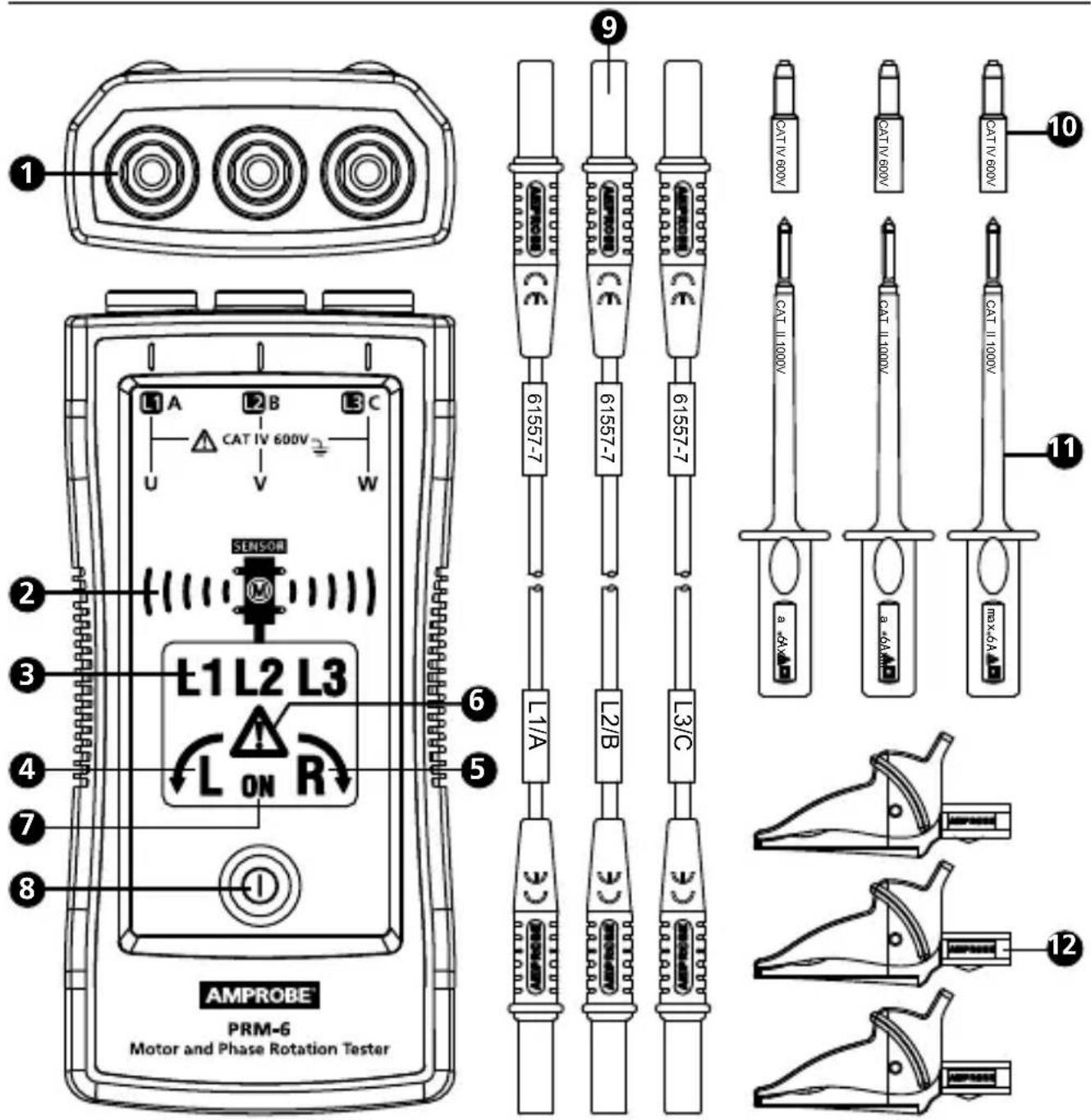
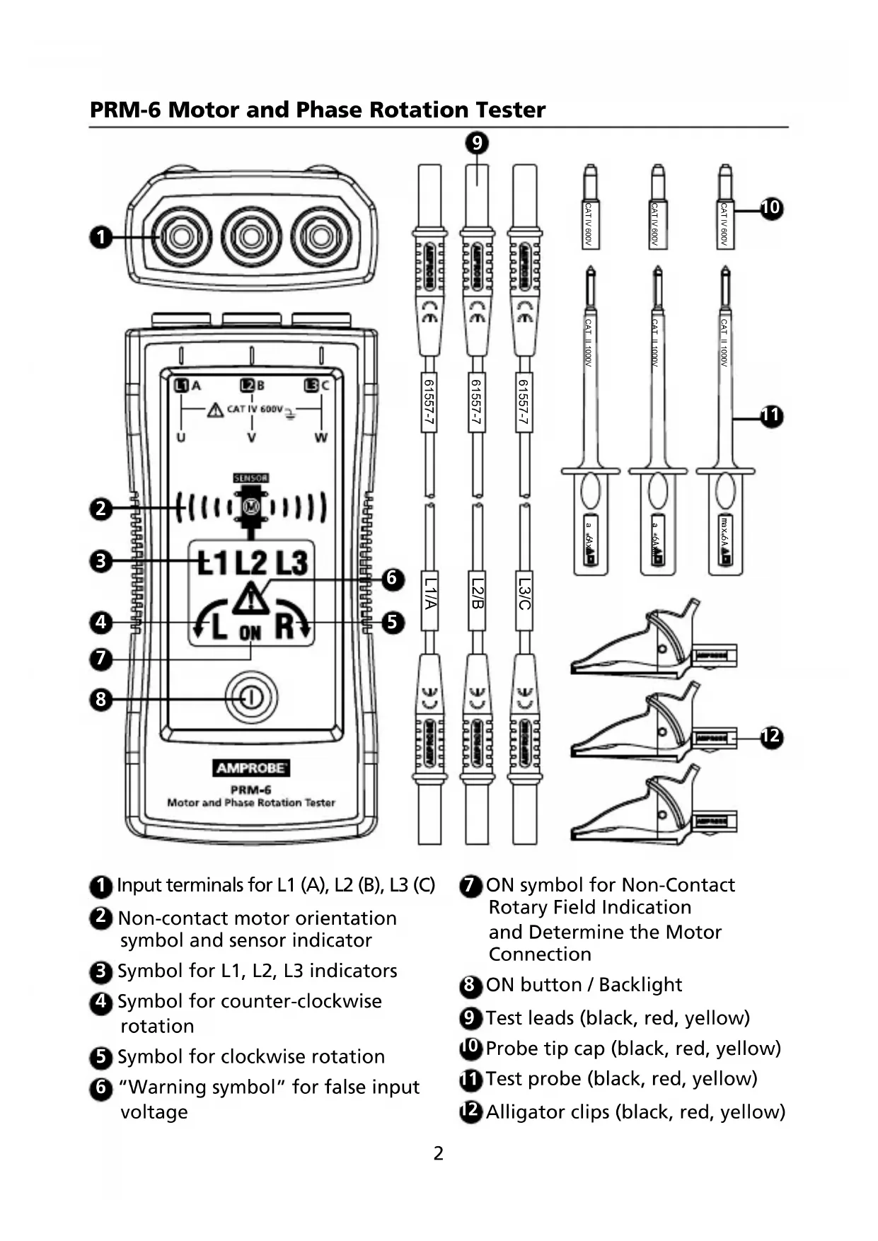
Input terminals for L1 (A), L2 (B), L3 (C)
Non-contact motor orientation symbol and sensor indicator
Symbol for L1, L2, L3 indicators
Symbol for counter-clockwise rotation
Symbol for clockwise rotation
"Warning symbol" for false input voltage
ON symbol for Non-Contact Rotary Field Indication and Determine the Motor Connection
ON button / Backlight
Test leads (black, red, yellow)
10 Probe tip cap (black, red, yellow)
Test probe (black, red, yellow)
12 Alligator clips (black, red, yellow)
SYMBOLS
| A | Caution! Risk of electric shock. |
| A | Caution! Refer to the explanation in this manual. |
| 回 | The equipment is protected by double insulation or reinforced insulation |
| ⊥ | Earth (Ground) |
| CAT IV | Measurement category IV (CAT IV) is for measurement performed at the source of the low-voltage installation. Examples are electricity meters and measurement on primary overcurrent protection device and ripple control units. |
| Orientation symbol for non-contact motor rotary field indication. | |
| CE | Complies with European Directives. |
| Conforms to relevant Australian standards | |
| C US | Canadian Standards Association (NRTL/C). |
| Do not dispose of this product as unsorted municipal waste. Contact a qualified recycler. |
SAFETY INFORMATION
The meter complies with:
IEC/EN 61557-1/-7
IEC/EN 61010-1 3rd Edition, UL61010-1 3rd Ed. and CAN/CSA C22.2 No. 61010-
1-12 to CAT IV 600 V, pollution degree 2
IEC/EN 61010-2-030
IEC/EN 61010-2-31 for test leads
EMC IEC/EN 61326-1
CENELEC Directives
The instruments conform to CENELEC low-voltage directive 2006/95/EC and electromagnetic compatibility directive 2004/108/EC.
Warning
To prevent possible electrical shock, fire, or personal injury:
- Carefully read all instructions. Read safety information before using or servicing the tester.
- Comply with local and national safety codes. Use personal protective equipment (approved rubber gloves, face protection, and flame resistant clothes) to prevent shock and arc blast injury where hazardous live conductors are exposed.
- Use the product only as specified, or the protection supplied by the product can be compromised.
Do not work alone. - Consider mechanical risks and risks of rotating mechanical parts. Comply with local and national safety codes.
- Do not use the tester or test leads if they appear damaged. Examine the tester and test leads for damaged insulation or exposed metal. Check test lead continuity. Replace damaged test leads before using the tester.
- Do not touch voltages >30V AC RMS, 42 V AC peak, or 60 V DC. These voltages pose electrical shock hazards. Keep fingers behind the finger guards on the probes and alligator clips.
- To avoid false readings, which could lead to possible electric shock or personal injury, check the battery and verify operation beforehand on a known source.
- Do not exceed the Measurement Category (CAT) rating of the lowest rated individual component of a product, probe, or accessory.
- If the tester is used in a manner not specified in the users manual, the protection provided by the equipment may be impaired.
- Measurements can be adversely affected by impedances of additional operating circuits connected in parallel or by transient currents.
- Do not use the PRM-6 with any of the parts removed.
- Disconnect the test leads from energized circuits and from the tester before opening the battery cover.
- Do not use the product around explosive gas, vapor, or in damp or wet environments.
- Have the tester serviced only by qualified service personnel.
- Only use the test lead sets provided with the tester. Alternative test leads may not fulfill the requirements of EN 61557-7.
Your shipping carton should include:
1 PRM-6 Motor and Phase Rotation Tester
3 Test leads (black, red, yellow)
3 Test probes (black, red, yellow)
3 Alligator clips (black, red, yellow)
2 1.5V AAA battery (installed)
1 Users manual
1 Carrying case
If any of the items are damaged or missing, return the complete package to the place of purchase for an exchange.
USING MOTOR AND PHASE ROTATION TESTER
Determine the Rotary Field Direction
To determine the rotary field direction:
- Connect one end of test leads to the tester's corresponding terminals L1, L2, and L3.
- Connect the alligator clips or the test probes to the other end of the test leads.
- Connect the alligator clips/test probes to the three mains phases.
- L1, L2 and L3 indicators shows voltage is present.
- The clockwise or counter-clockwise rotary indicator shows the type of rotary field direction present.
- If the "Warning Symbol" illuminates, either one or two of the inputs are connected to the neutral conductor or the voltage difference between the phases exceed 30% phase to phase or 65% between phase to neutral.
Note:
- The PRM-6 is powered by the motor or system being tested.
- In environment with poor light condition you can switch on the Backlight while pressing and hold button "ON" to improve visibility.
Warning
The rotary indicator L1, L2 and L3 lights even if the neutral conductor, N, is connected instead of L1, L2, or L3. Refer to Figure 1 for more information about what appears on the back of the PRM-6).
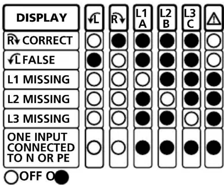
Figure 1: Phase indication table (also printed on the back of the PRM-6)
Non-Contact Rotary Field Indication
For non-contact rotary field indication:
- Disconnect all test leads from the PRM-6 for safety reason.
- Position the PRM-6 on the motor so it is parallel to the length of the motor shaft. The sensor of the tester should be in the center of the motor windings. The tester should be as close as possible to the motor. See Figure 2.
- Press and hold the ON button. The LC display shows "ON," indicating the PRM-6 is ready for testing.
- Either the clockwise or counter-clockwise rotary indicator will illuminate, showing the type of rotary field direction present.
If the LC display don't show the "ON" symbol, while pressing the ON button, the battery does not have a charge and needs to be replaced.
The Indicator will not operate with motor controlled by frequency converters. The bottom of the PRM-6 should be oriented towards the drive shaft. See the Orientation Symbol on the PRM-6.
If the motor was disconnected from electricity for a long time (typically one year), the residual field / magnetization may be too weak for the tester to measure the rotation.
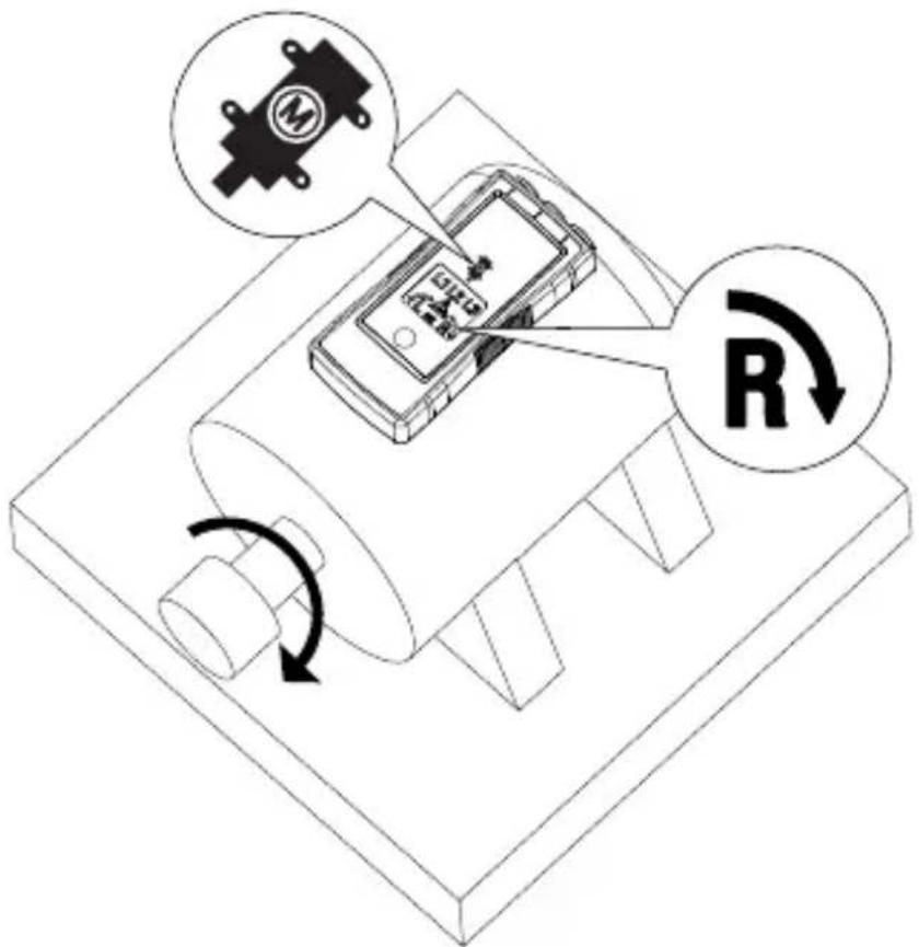
Figure 2: Motor Rotation
Determine the Motor Connection
- Connect one end of test leads to the tester's corresponding terminals L1, L2, and L3.
- Connect the alligator clips or the test probes to the other end of the test leads.
- Connect the alligator clips or test probes to the motor connections, L1 to U, L2 to V, L3 to W.
- Press the ON button. The LC display shows "ON," indicating the PRM-6 is ready for testing.
- Turn the motor shaft towards the right.
- Either the clockwise or counter-clockwise rotary indicator will illuminate, showing the rotary field direction.
If the LC display don't show the "ON" symbol, while pressing the ON button, the battery does not have a charge and needs to be replaced.
Note: If you get a another indication of the rotary field direction as expected then swap two connection from step 3 and repeat testing. Use the new order of U (L1), V (L2) and W (L3) for further purpose
Backlight
The backlight is turned on while pressing and hold button "ON" and it is powered by the battery.
If the backlight don't illuminate the battery does not have a charge and needs to be replaced.
SPECIFICATIONS
| 3 phase indication | Via LCD |
| Indication of phase rotation | Via LCD |
| Indication of motor rotation direction Non-contact rotary field indication | Via LCD |
| Determine the motor connection | Via LCD |
| LC display backlight | Yes |
| Determine Rotary Field Direction | |
| Frequency range (fn) / Voltage range (Ume) | 16...60 Hz / 40...700V AC phase to phase >60...400 Hz / 50...700V AC phase to phase |
| Indicator for false input voltage | difference of > ±30% between the phase to phase voltages (> ± 65% between phase to neutral voltages) |
| Nominal test current (In in per phase) | ≤ 3.5 mA |
| Non-Contact Rotary Field Indication | |
| Frequency range (fn) | 16 to 400 Hz |
| Determine the Motor Connection | |
| Voltage range (Ume) | ≥ 1 V AC phase to phase |
| Frequency range (fn) | 2 to 400 Hz |
| General Specifications | |
| Operating time | Continuous |
| Operating temperature | 0°C to 40°C (32°F to 104°F) |
| Operating altitude | Up to 2000 m |
| Humidity (Without condensation) | ≤ 80% RH |
| Storage conditions | 0°C to 40°C (32°F to 104°F), ≤ 80% RH |
| Power supply | 2 x 1.5 V AAA alkaline battery |
| Battery life | Minimum 2 years for average use |
| Dust/water resistance | IP 40 |
| Pollution degree | 2 |
| Dimensions (H x W x D) | 137 x 65 x 33 mm (5.43 x 2.56 x 1.3 in) |
| Weight | 170 g (0.38 lb) (battery installed) |
| Product Standard | EN 61557 -1/-7 |
| Electrical safety | EN 61010-1, EN 61557-7 |
| Overvoltage category | CAT IV 600 V |
| EMC | Conforms to EN 61326-1 |
| Agency approvals | © US C E |
MAINTENANCE

Caution
To prevent damage to the PRM-6:
- Do not attempt to repair or service the PRM-6 unless qualified to do so.
- Make sure that the relevant calibration, performance test, and service information is being used.
- Do not use abrasives or solvents. Abrasives or solvents will damage the PRM-6 case.
Cleaning
The only maintenance the PRM-6 requires is inspection and cleaning. Periodically wipe the case with a mild solution of detergent and water. Apply sparingly with a soft cloth and allow to dry completely before using. Do not use aromatic hydrocarbons, gasoline or chlorinated solvents for cleaning.
Replacing and Disposing of the Battery
Warning
- To avoid electric shock, disconnect the test leads from the source before opening the PRM-6 for battery replacement.
- To avoid false readings, which could lead to possible electric shock or personal injury, replace the battery as soon as the battery is low or dead.

Note: The PRM-6 contains alkaline battery. Do not dispose of the battery with other solid waste.
Used batteries should be disposed of by a qualified recycler or hazardous materials handler. Contact your authorized Amprobe Service center for recycling information.
The PRM-6 uses two 1.5 V AAA batteries (supplied). To replace the batteries, follow these steps and refer to Figure 3:
- Disconnect test leads from any power source.
- Place the PRM-6 face down on a nonabrasive surface and loosen the battery-door lock with a flat screwdriver.
- Lift the battery cover away from the PRM-6.
- Replace the batteries as shown in Figure 3. Observe the battery polarity shown in the battery compartment.
- Replace the battery cover to the lock position.
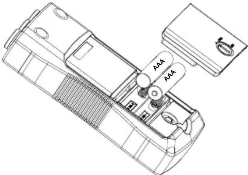
Figure 3: Replacing batteries
PRM-6
Visit www.Amprobe.com for
Catalog
Application notes
Product specifications
- User manuals
Amprobe
www.Amprobe.com
info@amprobe.com
Everett, WA 98203
Tel: 877-AMPROBE (267-7623)
Amprobe Europe
Beha-Amprobe
In den Engematten 14
79286 Glottertal, Germany
Tel.: +49 (0) 7684 8009 - 0

Please Recycle
- MOTOR AND PHASE ROTATION TESTER
- USER MANUAL
- LIMITED WARRANTY AND LIMITATION OF LIABILITY
- REPAIR
- IN-WARRANTY REPAIRS AND REPLACEMENT – ALL COUNTRIES
- NON-WARRANTY REPAIRS AND REPLACEMENT – UNITED STATES AND CANADA
- NON-WARRANTY REPAIRS AND REPLACEMENT – EUROPE
- CONTENTS
- SAFETY INFORMATION
- CENELEC DIRECTIVES
- WARNING
- USING MOTOR AND PHASE ROTATION TESTER
- DETERMINE THE ROTARY FIELD DIRECTION
- NOTE
- NON-CONTACT ROTARY FIELD INDICATION
- THE INDICATOR WILL NOT OPERATE WITH MOTOR CONTROLLED BY FREQUENCY CONVERTERS. THE BOTTOM OF THE PRM-6 SHOULD BE ORIENTED TOWARDS THE DRIVE SHAFT. SEE THE ORIENTATION SYMBOL ON THE PRM-6
- DETERMINE THE MOTOR CONNECTION
- BACKLIGHT
- MAINTENANCE
- CAUTION
- CLEANING
- REPLACING AND DISPOSING OF THE BATTERY
- PRM-6
- VISIT WWW.AMPROBE.COM FOR
Brand : Amprobe
Model : PRM6
Category : Multimeter