VPC10A - Multimeter Amprobe - Free user manual and instructions
Find the device manual for free VPC10A Amprobe in PDF.
User questions about VPC10A Amprobe
0 question about this device. Answer the ones you know or ask your own.
Ask a new question about this device
Download the instructions for your Multimeter in PDF format for free! Find your manual VPC10A - Amprobe and take your electronic device back in hand. On this page are published all the documents necessary for the use of your device. VPC10A by Amprobe.
USER MANUAL VPC10A Amprobe
Voltage & Continuity Tester
User Manual
Limited Warranty and Limitation of Liability
Your Amprobe product will be free from defects in material and workmanship for one year from the date of purchase unless local laws require otherwise. This warranty does not cover fuses, disposable batteries or damage from accident, neglect, misuse, alteration, contamination, or abnormal conditions of operation or handling. Resellers are not authorized to extend any other warranty on the behalf of Amprobe. To obtain service during the warranty period, return the product with proof of purchase to an authorized Amprobe Service Center or to an Amprobe dealer or distributor. See Repair Section for details. THIS WARRANTY IS YOUR ONLY REMEDY. ALL OTHER WARRANTIES - WHETHER EXPRESS, IMPLIED OR STATUTORY - INCLUDING IMPLIED WARRANTIES OF FITNESS FOR A PARTICULAR PURPOSE OR MERCHANTABILITY, ARE HEREBY DISCLAIMED. MANUFACTURER SHALL NOT BE LIABLE FOR ANY SPECIAL, INDIRECT, INCIDENTAL OR CONSEQUENTIAL DAMAGES OR LOSSES, ARISING FROM ANY CAUSE OR THEORY. Since some states or countries do not allow the exclusion or limitation of an implied warranty or of incidental or consequential damages, this limitation of liability may not apply to you.
Repair
All Amprobe tools returned for warranty or non-warranty repair or for calibration should be accompanied by the following: your name, company's name, address, telephone number, and proof of purchase. Additionally, please include a brief description of the problem or the service requested and include the test leads with the meter. Non-warranty repair or replacement charges should be remitted in the form of a check, a money order, credit card with expiration date, or a purchase order made payable to Amprobe.
In-warranty Repairs and Replacement – All Countries
Please read the warranty statement and check your battery before requesting repair. During the warranty period, any defective test tool can be returned to your Amprobe distributor for an exchange for the same or like product. Please check the "Where to Buy" section on amprobe.com for a list of distributors near you. Additionally, in the United States and Canada, in-warranty repair and replacement units can also be sent to an Amprobe Service Center (see address below).
Non-warranty Repairs and Replacement – United States and Canada
Non-warranty repairs in the United States and Canada should be sent to an Amprobe Service Center. Call Amprobe or inquire at your point of purchase for current repair and replacement rates.
USA: Canada:
Amprobe
Amprobe
Everett, WA 98203
Mississauga, ON L4Z 1X9
Tel: 877-AMPROBE (267-7623)
Tel: 905-890-7600
Non-warranty Repairs and Replacement – Europe
European non-warranty units can be replaced by your Amprobe distributor for a nominal charge. Please check the "Where to Buy" section on beha-amprobe.com for a list of distributors near you.
Beha-Amprobe*
In den Engematten 14
79286 Glottertal, Germany
Tel.: +49 (0) 7684 8009 - 0
beha-amprobe.com
* (Correspondence only – no repair or replacement available from this address. European customers please contact your distributor.)
CONTENTS
SYMBOL....3
SAFETY INFORMATION .... 3
UNPACKING AND INSPECTION ....5
FEATURES......5
Automatic Operation....6
Voltage Measurement......6
Continuity Testing 8
DETAILED SPECIFICATIONS 8
MAINTENANCE 10
Cleaning 10
Replacing the Battery....10
text_image
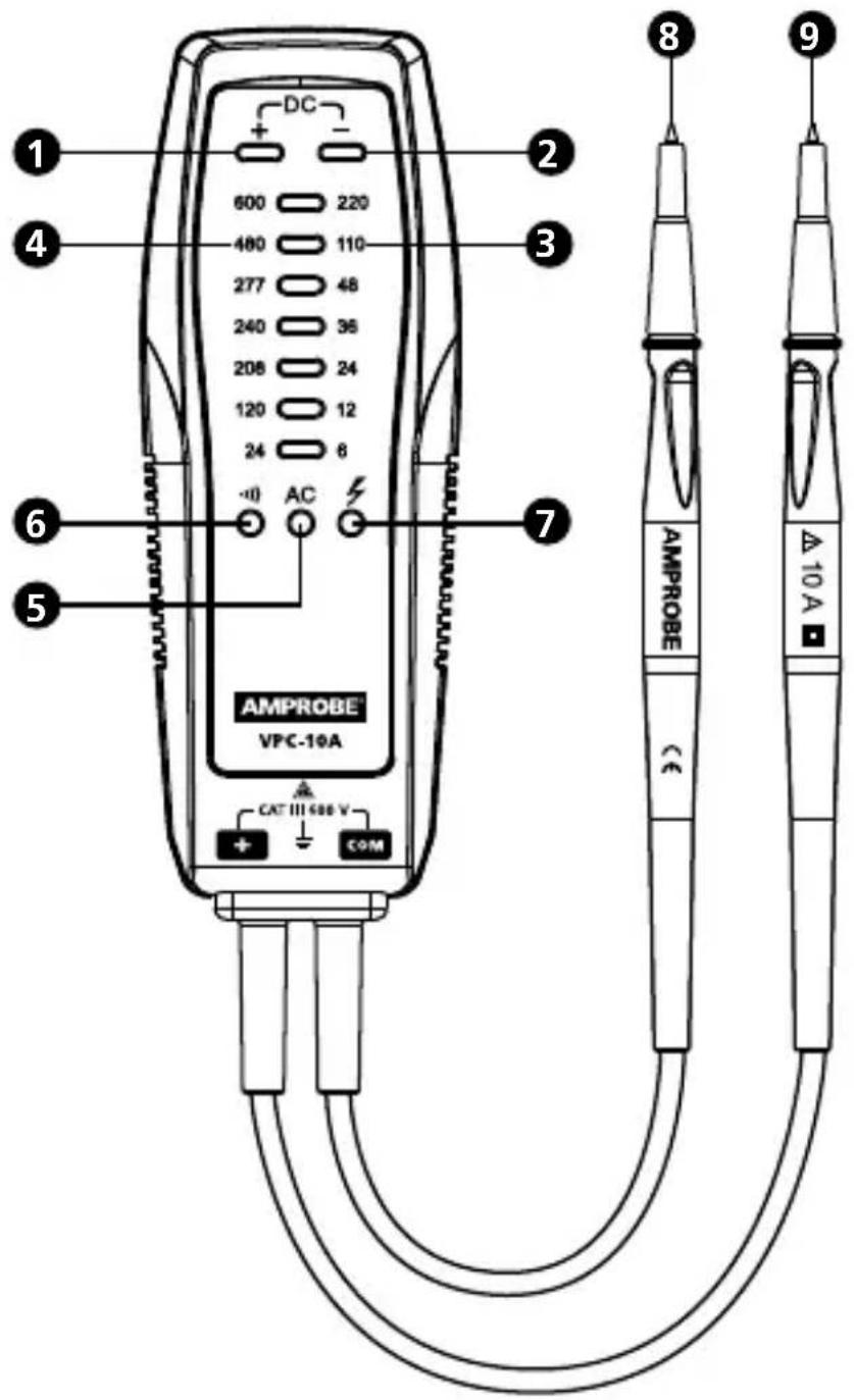
DC 600 220 480 110 277 48 240 36 208 24 120 12 24 8 AC AMPROBE VPC-10A CAT III 686 V COM + - ① ② ③ ④ ⑥ ⑦ ⑧ ⑨ AMPROBE (€) △10A1 Positive DC voltage LED indicator
2 Negative DC voltage LED indicator
3 DC voltage range
4 AC voltage range
5 AC voltage LED indicator
6 Continuity LED indicator
7 Hazardous voltage LED indicator
8 Measuring probe (COM)
9 Measuring probe (+)
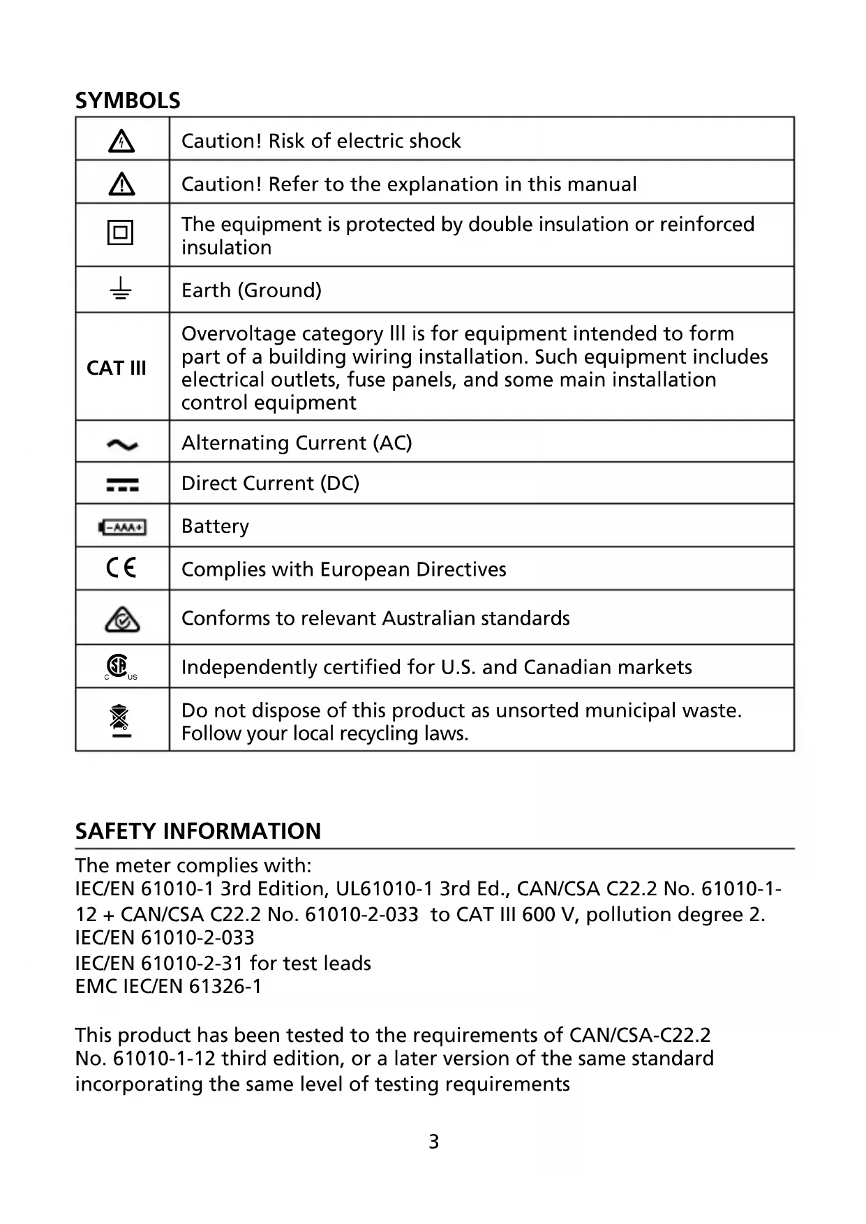
SYMBOLS
 | Caution! Risk of electric shock |
 | Caution! Refer to the explanation in this manual |
 | The equipment is protected by double insulation or reinforced insulation |
 | Earth (Ground) |
| CAT III | Overvoltage category III is for equipment intended to form part of a building wiring installation. Such equipment includes electrical outlets, fuse panels, and some main installation control equipment |
 | Alternating Current (AC) |
 | Direct Current (DC) |
 | Battery |
 | Complies with European Directives |
 | Conforms to relevant Australian standards |
 | Independently certified for U.S. and Canadian markets |
 | Do not dispose of this product as unsorted municipal waste. Follow your local recycling laws. |
SAFETY INFORMATION
The meter complies with:
IEC/EN 61010-1 3rd Edition, UL61010-1 3rd Ed., CAN/CSA C22.2 No. 61010-1-
12 + CAN/CSA C22.2 No. 61010-2-033 to CAT III 600 V, pollution degree 2.
IEC/EN 61010-2-033
IEC/EN 61010-2-31 for test leads
EMC IEC/EN 61326-1
This product has been tested to the requirements of CAN/CSA-C22.2
No. 61010-1-12 third edition, or a later version of the same standard
incorporating the same level of testing requirements
CENELEC Directives
The instruments conforms to CENELEC low voltage directive 2014/35/EU and electromagnetic compatibility directive 2014/30/EU
⚠️ Warning
To prevent possible electrical shock, fire, or personal injury:
- Carefully read all instructions. Read safety information before using or servicing the tester.
- Comply with local and national safety codes. Use personal protective equipment (approved rubber gloves, face protection, and flame retardant clothing) to prevent shock and arc blast injury where hazardous live conductors are exposed.
- In CAT III environments, use the test probes with the probe caps on. This decreases the exposed probe tip to reduce the possibility of an arc flash from short circuits. When the probe cap is off, the probe tip is 18 mm and rated to 1000V CAT II.
- Use the product only as specified, or the protection supplied by the product can be compromised.
- Do not work alone.
- Do not use the tester or test leads if they appear damaged. Examine the instrument and test leads for damaged insulation or exposed metal. Check test lead continuity.
- Do not touch voltages >30 V AC rms, 42 V AC peak, or 60 V DC. These voltages pose electrical shock hazards. Keep fingers behind the finger guard on the probe.
- To avoid false readings, which could lead to possible electric shock or personal injury, check the battery and verify operation on a known source prior to measuring hazardous voltages (voltages above 30 V AC rms, 42 V AC peak and 60 V DC).
- indicates hazardous voltage present if the LED turns on.
- Do not exceed the measurement category (CAT) rating of the lowest rated individual component of a product, probe, or accessory.
- If the tester is used in a manner not specified in the user manual, the protection provided by the equipment may be impaired.
- Measurements can be adversely affected by impedances of additional operating circuits connected in parallel or by transient currents.
- Disconnect the test leads from energized circuits and from the tester before replacing the battery.
- Do not use the tester with battery door removed.
- Do not use the instrument around explosive gas, vapor, or in damp or wet environments.
- For indoor use only.
Your shipping carton should include:
1 VPC-10A Voltage & Continuity Tester
3 Batteries 1.5V IEC LR03 AAA
1 User manual
If any of the items are damaged or missing, return the complete package to the place of purchase for an exchange.
FEATURES
The Amprobe VPC-10A voltage and continuity tester is designed to be rugged and easy to use for testing voltage and continuity. It offers seven different voltage indicators clearly differentiating between key voltage levels and a buzzer alert indicating the presence of dangerous voltages and continuity.
- Determine voltage presence in receptacles, light fixtures or extension cords
- Test continuity of fuses, light bulbs and electrical connections
- Automatically selects AC voltage, DC voltage or continuity
• LEDs lights indicate 7 levels of AC and DC voltages: - V AC: 24, 120, 208, 240, 277, 480, 600
- V DC: 6, 12, 24, 36, 48, 110, 220
• Full range polarity detection - Continuity buzzer and visual continuity indication
- Do not use on a voltage source higher than AC 600 V and/or DC 600V between any terminal and earth ground.
- Connecting test leads:
- Connect the common (COM) test lead to the circuit before connecting the live lead.
- After measuring, remove live lead before removing the common (COM) test lead from the circuit.
-
Test on a known live source within the rated AC/DC voltage range of the instrument, both before and after use to ensure the instrument is in good working condition.
-
Indicates hazardous voltage levels if the LED turns on.
-
Do not touch voltages >30 V AC rms, 42 V AC peak, or 60 V DC. These voltages pose electrical shock hazards. Keep fingers behind the finger guard on the probe.
Automatic Operation
The tester automatically turns on when you place the probes across a complete circuit. The tester selects AC or DC voltage or continuity mode based on the resistance or voltage between the probes. The tester automatically turns off when you remove the probes from the circuit under measurement.
Voltage Measurement
Connect test leads across the source or load under measurement, the LEDs turns on at between 70% and 100% of their rated voltages.
Note: The maximum testing voltage of this product is 600Vac/220Vdc. It will indicate 600Vac/220Vdc LED even if the testing voltage is greater than this limit. In this case, users should beware of electric shock, and operate with care or stop testing.
AC Voltage: 600V rms maximum, 50 to 60Hz
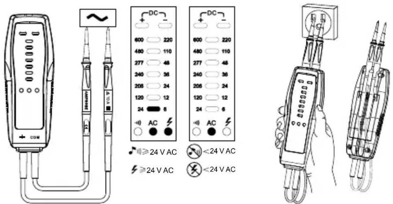
text_image
DC 600 220 480 110 277 48 240 38 208 24 120 12 24 8 AC DC 600 220 480 110 277 48 240 38 208 24 120 12 24 8 AC ≥24 V AC <24 V AC ≥24 V AC <24 V ACFigure 1: AC Voltage measurement Figure 2: Check for voltage presence in electrical outlets
DC Voltage: 600V maximum
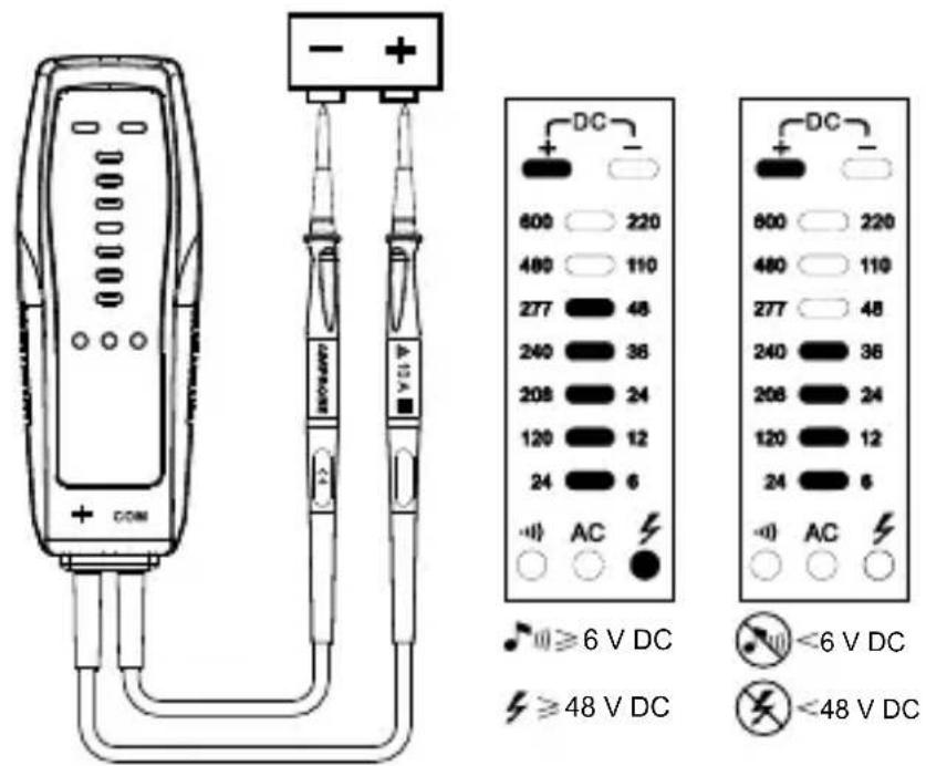
text_image
COM - + 600 220 480 110 277 48 240 36 208 24 120 12 24 6 AC DC + - 800 220 480 110 277 48 240 36 208 24 120 12 24 6 AC <6 V DC ≥48 V DC <48 V DCFigure 3: +DC voltage measurement
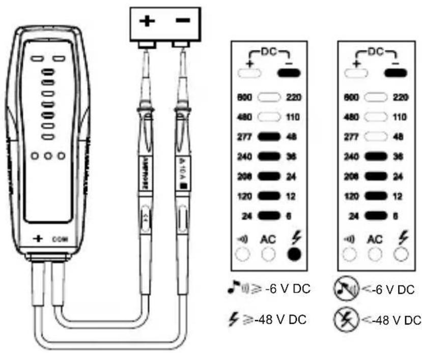
text_image
DC 800 220 480 110 277 48 240 36 208 24 120 12 24 6 -0) AC + COM + - - 600 220 480 110 277 48 240 36 208 24 120 12 24 6 -0) AC + - - 600 220 480 110 277 48 240 36 208 24 120 12 24 6 -0) AC + - - ≥ -6 V DC ≥ -48 V DC ≤ -6 V DC ≤ -48 V DCFigure 4: -DC voltage measurement
Continuity Testing
Disconnect circuit power and discharge all high-voltage capacitors before testing continuity. Short circuit=0 - 45 kΩ
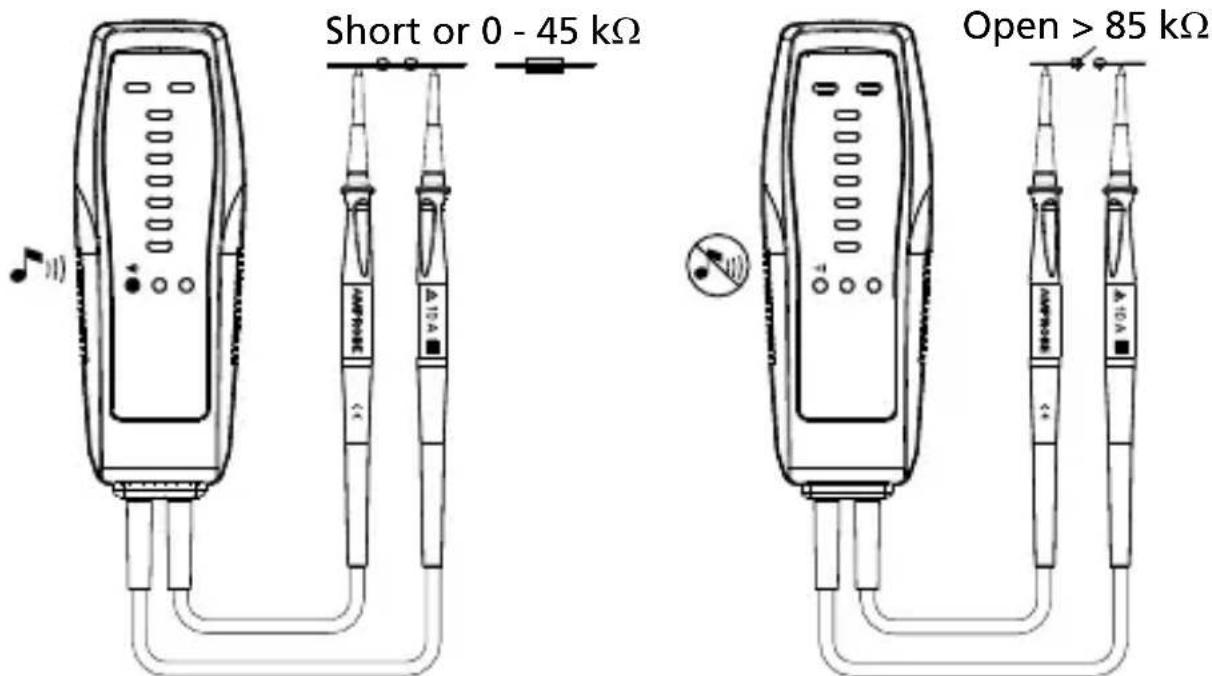
text_image
Short or 0 - 45 kΩ Open > 85 kΩFigure 5: Continuity testing
DETAILED SPECIFICATIONS
| LED voltage range | 24 - 600 VAC6 - 220 VDC |
| LED indicator | AC volts: 24 V, 120 V, 208 V, 240 V, 277 V, 480 V, 600 VDC volts: 6 V, 12 V, 24 V, 36 V, 48 V, 110 V, 220 V |
| Frequency range 50 to 60 Hz | |
| Hazardous voltage indication | ≥ 24 V AC, ≥ 48 V DC |
| Acoustic indication ≥ 24 | VAC, ≥ 6 VDC |
| Tolerances LEDs -30% to 0% of reading | |
| Voltage detection Automatic | |
| Range detection Automatic | |
| Polarity detection Full range | |
| Continuity range 0 – 45 | kΩ |
| Continuity tolerances 0% to +50% | |
| Continuity buzzer 3 kHz | |
| Continuity indication | LED and buzzer0 - 45 kΩ ON; >85 kΩ OFF |
| Input impedance 1 MΩ | |
| Operating time | 30 seconds ON maximum and wait for 5 minutes before making another measurement |
| Operating altitude Up to 2000 m / 6561 feet | |
| Operating temperature 41 °F to 122°F / 5°C to 50°C | |
| Storage conditions -22 | °F to 140°F / -30°C to 60°C |
| Humidity(without condensation) | ≤ 80% RH at 41°F to 104°F / 5°C to 40°C;≤ 50% RH at 104°F to 122°F / 40°C to 50°C |
| Pollution degree 2 | |
| Power supply Three 1.5 V batteries, AAA, LR03, UM4 | |
| Battery life 40 hours (alkaline) (typical) | |
| Dimensions (H x W x D) | 5.90 x 2.13 x 1.34 in150 x 54 x 34 mm |
| Weight | Approximately 0.45 lb (205 g) with batteries installed |
| Electrical safety | CAN/CSA-C22.2 No. 61010-1-12, UL Std. No.61010-1 (3rd Edition),CAN/CSA-C22.2 No. 61010-031-07,UL 61010-031(1st Edition - 2007),CAN/CSA-C22.2 No. 61010-2-030-12, UL 61010-2-030(1st Edition -2012) |
| Overvoltage category CAT III 600 V | |
| EMC Conforms to IEC 61326-1 | |
| Agency approvals |  |

Caution - To prevent damage to the VPC-10A:
- Do not attempt to repair or service the VPC-10A unless qualified to do so.
- Make sure that the relevant calibration, performance tests, and service information is being utilized.
- Do not use abrasives or solvents.
Cleaning
The only maintenance the VPC-10A requires is inspection and cleaning. Periodically wipe the case with a mild solution of detergent and water. Apply sparingly with a soft cloth and allow time to dry completely before using. Do not use aromatic hydrocarbons, gasoline or chlorinated solvents for cleaning.
Replacing the Battery
Replace the batteries immediately if the continuity LED doesn't turn on when touching both probes together.

⚠ Warning
- To avoid electric shock, disconnect the test leads from the source before opening the VPC-10A for battery replacement.
- To avoid false readings, which could lead to possible electric shock or personal injury, replace the battery as soon as the battery is low or dead.
The VPC-10A uses three 1.5V batteries. To replace the batteries, follow these steps and refer to Figure 6:
- Disconnect test leads from any power source.
- Place the VPC-10A face down on a non-abrasive surface and loosen the battery-door screw with a Phillips screwdriver.
- Lift the battery cover away from the VPC-10A.
- Replace the battery as shown in Figure 6. Observe the battery polarity shown in the battery compartment.
- Secure the battery cover back in position with the screw.
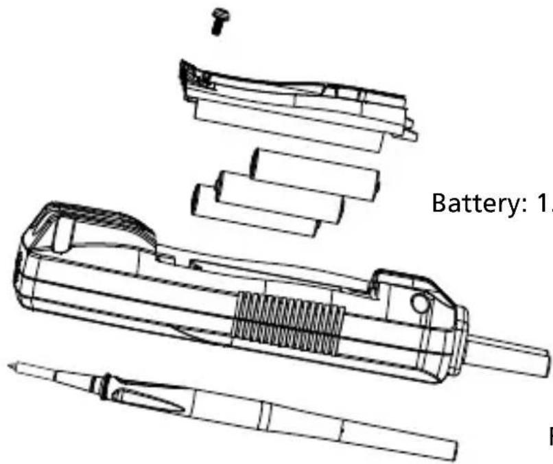
text_image
Battery: 1.Battery: 1.5V IEC LR03 AAA
Figure 6: Replacing the batteries
VPC-10A
text_image
Diagram of a handheld electronic device with labeled ports and connections, including a 10A microcontroller and a note indicating sound.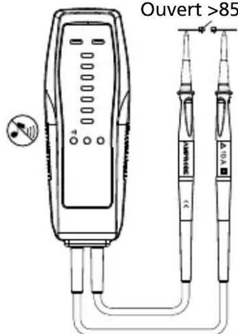
text_image
Ouvert >85 A10A 10A- V DC: 6, 12, 24, 36, 48, 110, 220
Visit amprobe.com for
- Catalog
- Application notes
• Product specifications - User manuals
Amprobe®
amprobe.com
info@amprobe.com
Everett, WA 98203
Tel: 877-AMPROBE (267-7623)
Beha-Amprobe®
beha-amprobe.com
In den Engematten 14
79286 Glottertal, Germany
Tel.: +49 (0) 7684 8009 - 0

Please
Recycle