CB15A - Boiler FAGOR - Free user manual and instructions
Find the device manual for free CB15A FAGOR in PDF.

| Product type | Electric water heater |
| Brand | Fagor |
| Model | CB15A |
| Capacity | 15 liters (estimated) |
| Power supply | 230 V ~ 50 Hz |
| Power | 1500 W (estimated) |
| Temperature range | 30 °C to 70 °C |
| Energy saving mode | Position E at 55 °C |
| Safety devices | Safety thermostat, hydraulic safety group, pressure limiter |
| Installation | Horizontal or vertical, by a qualified professional |
| Maintenance | External cleaning with soft damp cloth; no abrasives |
| Included accessories | Safety valve, insulating sleeves |
| Approximate weight | 8 kg (estimated) |
| Approximate dimensions (H x W x D) | 400 x 350 x 350 mm (estimated) |
| Compliance | IEC 60364-7-701 (bathroom) |
Frequently Asked Questions - CB15A FAGOR
User questions about CB15A FAGOR
0 question about this device. Answer the ones you know or ask your own.
Ask a new question about this device
Download the instructions for your Boiler in PDF format for free! Find your manual CB15A - FAGOR and take your electronic device back in hand. On this page are published all the documents necessary for the use of your device. CB15A by FAGOR.
USER MANUAL CB15A FAGOR
CONGRATULATIONS. You have decided to acquire an electric water heater from FAGOR. We are a prestigious brand and our top priority is fulfilling the needs of our customers, solving them in advance via our innovative state of the art products. Our specialists have carefully manufactured and inspected all our FAGOR electric water heaters in order to provide an ideal response to their needs.
Thank you for the confidence placed in us.
The correct operation of a water heater does not only depend on the quality of the product, but also on its correct installation by a trained professional.
Read this manual carefully before installing and using your water heater in order to achieve its highest performance and extend its life cycle. Keep this manual for future use.
SAFETY AND GENERAL WARNINGS
- The installation and first use must be performed according to these instructions and only by trained professionals. (See the installation section).
- FAGOR water heaters are manufactured and tested according to current regulations.
- This device can be used by children age 8 and older, by physically, sensory or mentally handicapped persons, or persons without proper experience or knowledge, if they have received appropriate supervision or training regarding the safe use of the device and understand the dangers involved. Children should not play with the device. Cleaning and maintenance of the device should not be performed by unsupervised children.
- If the power cable is damaged it must be replaced by the manufacturer, its post-sales department or similarly trained personnel in order to prevent any risks.
- The pressure limiter device must be used often in order to remove lime deposits and verify it is not blocked.
- The water heater does not need any specific maintenance. Before cleaning the device, disconnect it. Scrubbing it with a smooth cloth or moist sponge is enough. Do not use abrasive materials or detergents.
ENVIRONMENT
Legislations and regulations for the protection of the environment are strictly observed (2002/96/EC guideline on electric and electronic waste).
INFORMATION FOR THE CORRECT MANAGEMENT OF RESIDUES FROM ELECTRIC AND ELECTRONIC DEVICES
At the end of its life cycle, it should not be disposed of mixed with general wastes.
It can be delivered, without any cost, to specific waste collection centers, designed by local administrations, or to suppliers that provide this service.
Disposing of the electric device separately serves to prevent possible harmful consequences for environment and health derived from an incorrect disposal, and permits a correct treatment and recycling of its materials, which result in important energy and resources savings.
For further information, contact the local authorities or the store where you acquired the product.
MALFUNCTIONS OR BREAKDOWN
If your water heater presents any malfunctions, immediately disconnect the device from the electrical power supply. Report to the Technical Assistance Service.
In order to facilitate the tasks of the Technical Assistance Service, please provide the following data:
- Heater model.
- Series number.
Purchase date. - Description of the problem.
- Address and phone number.
Full name of the contact person.
INSTALLATION
ACCESORIES
This electric water heater includes the basic installation elements which are found in the packaging, i.e.:
- Insulating bushing for pipes.
Safety valve.
The accessories are located within the packaging.
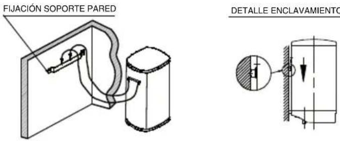
WALL MOUNTING PROCEDURE
Both the wall and the screws and Rawl-plugs should be capable of withstanding the weight produced by a totally full heater. In case of low thickness walls, the wall should be reinforced.
NOTE.- The placement of the heater must allow access to the supply cable.
LOCATION
The installation procedure is greatly facilitated by being able to locate the unit horizontally or vertically anywhere in the house. It is advisable, however, to situate the unit as close as possible to where the hot water is to be used as pipe length reduction allows water temperature losses to be prevented.
A minimum 0,5m . space should be left underneath the pipe outlet for servicing.
As shown in the Figure 1 and 2, when installed horizontally, the input and output pipes must be located on the left. Should the unit be close to a wall, leave the minimum recommended space (0,5m) for maintenance and servicing operations.
Don't install the heater with its wall mounts againts the floor nor on a horizontal plane.
HYDRAULIC INSTALLATION
NOTE FOR INSTALLERS: the insulating sleeves found inside the packaging, must be located on the inlet/outlet pipes, using teflon on the screw of the pipes. Tightening torque for sleeves: 3.5Kg / m
Before proceeding to the hydraulic connexion, please rinse the connecting pipe in the order to avoid filth from entering inside the electric water heater.
Install the water heater according to the diagrams in figures 1 and 2.
a) The safety valve supplied with the heater MUST BE INSTALLED on the cold water input pipe.
No other hydraulic accessory can be installed between the safety valve and the cold water inlet pipe.
The outlet of the safety valve must be connected to a drain, whose diameter should be at least identical to inlet pipe. The inclination must be continuous and open, keeping a minimum distance of 20mm as shown in Figures 1 and 2. This pipe must be installed in an environment where freeze is not possible and with a downward slope. Water expands when heated, leaking (at leats a 3% per heating cycle). Do not worry, this is a standard phenomenon.
To empty the heater, operate the safety group hoisting the lever as shown on figure 3. We should act on said lever periodically to prevent it locks and check for proper operation.
In the models with upper connections, undo the components cover and undo the drainage bolt shown in figure 4.
b) If the water-supply pressure exceeds 5 bars, a type-approved reducing valve (between 3 or 4 bars) must be installed.
c) In case of plastic piping in the system, please take into account pressure and temperature conditions. Maximum pressure 9 bars and 70^ maximum temperature in standard conditions or 110^ in abnormal conditions when the safety thermostat cuts the energy supply.
ELECTRIC INSTALLATION
All storage water heaters are of 230V AC. Before connecting make sure that the mains supply and unit input features coincide.
The heater's installation procedure is totally straightforward and only requires that Low Voltage Electronic Regulations be met.
For installations in bathrooms and toilets Regulation IEC 60364-7-701 shall be adhered to.
VOLUME OF PROHIBITION: Zone 1 defined in figure 5.
No switches, sockets or lighting fixtures will be installed.
VOLUME OF PROTECTION: Zone 2 defined in figure 5.
No switches will be installed, however safety sockets or sockets protected by a 30mA circuit breaker may be installed.
The boiler should be installed outside the VOLUME OF PROHIBI-TION, in order to prevent water reaching the inside of the appliance. If the boiler has no plug, electrical power should be supplied through a bipolar switch with contact openings of at least 3mm . The installation should be protected with fuses of a calibre corresponding to the absorbed current. An earth connection should be included in every electrical installation. To make this connection, the boiler plug is provided with the appropriate contact, therefore it is enough for the base of the plug to correspond to that supplied with the appliance. If there is no regulatory "EARTH", we recommend the installation of a ≤ 30mA differential switch.
This appliance complies with the regulation on Radio-electric Disruption and interferences.
WARNING: always service the appliance with official aftersales, included the plug.
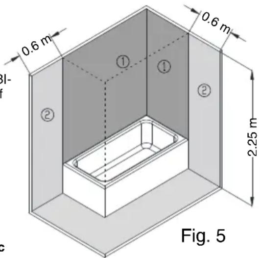
Fig. 5
USE
START UP
Filling up. Open the shutoff cock as soon as the heater has been installed. Open the hot water taps. Water appears as soon as the unit fills up completely. Close the taps and check the system for leaks.
Don't connect the heater to the power mains if uncertain as to whether it is full or not.
Electric Connection Plug into the mains and press the main power input switch. A light flashes on when the heating element is activated. The thermostat re-connects the heating element after a certain amount of water has been used.
Adjusting water temperature. Allows the user to adjust the temperature of hot water between about 30^ (minimum position) and 70^ (maximum position).
Position E. (Energy saving). The water reaches a temperature of about 55^ . In this position the heat losses are minimal and the formation of limescale is virtually eliminated.
It is advisable to have the heater plugged into the mains permanently as the thermostat will only activate the unit whenever it becomes necessary to maintain the selected temperature setting. The expanded polyurethane foaming will neutralize any potential heat loss.
How to empty the unit. The heater should be fully drained if left unused for extended periods or if subject to freezing hazards where
installed. This can be done by means of the safety valve.
Always remember to:
- Cut-off the power supply.
- Shut-off the input cock.
- Open the hot water tap.
MAINTENANCE
The water heater does not need any specific maintenance. Before cleaning the device, disconnect it. Scrubbing it with a smooth cloth or moist sponge is enough. Do not use abrasive materials or detergents.
Any overheating caused by thermostat failures is offset by the safety limiting device cutting both stages off and leaving the heater without power input.
Should any problem arise, the customer is advised to contact the After Sales Services.
THE MANUFACTURER reserves the right to modify the characteristics and specifications of all products without prion notice.
HYDRAULICKÁ INSTALACE
OBsIe IPEdUYPExKDeHnI NO B3OpACHOCTN
- YctaHOBka N BBOB B 3KcIIyaTaUIO DOJXHbI BblNOJIHTbcra TOLbKO KBaINΦuIPOBaHHbIMn CpeuaIInCTaMn COIaCHO daHHbIM INHCTpyKcIyAM (Cm. pa3dEe «YctaHOBka»).
-ИзгOTOBLEнe ИиСпытAne элЕКТрчecKx BODОHarpeBaTeJIeF FAGOR ПрОЗВОДЯТСАВ COOTBETCTBnC Tpe6OBAHnAМN DeICTByUOuNX HOpM I npaBnI. - 3TO yCTPOIcTBO MOryT nCnOJIb3OBaTb DeTn CTapWe 8 letn IInca C OrpaHnueHHbIMN fN3nueCKnMn, CeHCOPHBIMN JIn6o YmCTBeHHbIMN CnOCO6HOCTaMn INTe, y KOTOpbIX OTCyTCTByOT Heo6XoDnMbIe 3HaHnra INn ONbIT, eCIn INx DeIcTBnRA KOHTPOINpyOTc NIn eCIn OHn IpnOHCTpyKTIPOBaHbI OTHOCInTeJbHO 6e3OnaCHoro nCnOJIb3OBaHnRA YCTPOIcTBa IN OCO3HaIO T B03MOJHbIe PnCKn. DeTn He DoJXHbI INpArTb C BOJOHaRpeBaTeIeM. OuNcTKa IN o6CnyJKBaHne aAnpapaT MaOryT BblONHЯTbCSdEybMn TOJbKO NOD pPNCMOTpOM B3PoCJIbIX.
- YTO6bI n36eXaTb ONaChbIX CNTyaCn, 3aMeHa NOBpeKdEHHoro Ka6eJr NNtAHnJa DOLXHa IPOUN3BOuNTbcra N3ROTOBnteJeM, OΦNcuaJIbHOJ Cnyx6oJ NocIePnpOdaJxHOrO O6ClyXuVBaHnjaNN JIn JIncOM C COOTBeTCTByIOUeJ KBaIINΦNkCaunei.
- Heo6xodimo pergyraHNo 3aynckaTb B pa6Otu orpaHnUteIb daBleHnA Dn ydaJIeHnHaKnII n npOBepKn, YTO OH He 3a6JoknpoBaH.
- BODOHarpeBaTeIb He Tpe6yET CneuJIbHOrO TexHnueCKOrO
06cnyKuBaHnI. Ipeed npOBeDEHnEM OUnCTKn, Heo6XoJIMo OTKlIOUHTb
ero ot 3JeKTPoPntaHnI. OUnCTKa POn3BOJNTcMЯrKOJ TpAknO Jnn
BnaJHoI r6koJ 6e3 nCNoJIb3OBAHnI a6pa3INBhblx MaTePnaJIOB IN MOIoUnx
CpeDCTB.
OXPAHA OKPYXKAIOUCEI CPEIbl
3aKohbI n noJIOxKeHnO 03aunTe Okpykaiouei cpebl CTPOrO co6JIoudaIoTcA (DInpeKTnBa 2002/96/EC o6 OTxOax 3NeKtpuueckoro n 3neKTPoHHOrO o6OpuydoBaHn).
MHΦOPMAUJN NO YTNJIIN3ALIIN 3JEKTPNUECKOTO N 3JEKTPPOHHO O6OPYDOBAHNA
Pocne OKOHuaHnCpoka Cnyk6bl, daHHbI annapaT He dOnJKeH yTNJIIN3npoBaTcB MecTe C 6bITOBbIMN OTXoJaMn.
Bb moke Te cata B oIN H3 NyKTOB dNphipeHcnpoBaHHoro C6opa OTXOIOB, HaxOJaunCBA BeDMCTBe MeCTbIX OpraHOB Blactn INI INCTpN6bIoTOpY, IpeOCTaBIAHOUe My NOO6HbIe YcIyI.
Pa3dJIbHnA yTINI3aun 6bITOBbIX 3JIeKTpnpn6OpOB n03BOJnE rpeDOrBpaNTb BO3MOXhIe HeraTINBHe IocIeCTBnI dIg OKpykaIOSe Cpebl N3DOpOBb JIOde, KOTOpBle MOry IMeT MeCTo BCNECTBne HeIPpaBnIBHO yTINI3aUN, a TaKKe IO3BOJnE T NOBTOPO HO NCIOJIb3OBAbMb MaTePnaJIbI, BXODaUne B COCTAB 3TNX pIn6OpOB, IN DO6Ntbcra, TaKIM O6pa3OM, CyueCTBeHHoN 3KOHOOMN 3Heprnn n pecypcoB.
YTo6bI NOnUePKHyTb Heo6xOIMOCtB pa3dJIbHOy TnIIIN3aUN, Ha daHHOM aannapaTe HaHeceH 3HaK, npedynpejkaIOUI OTOM, To eRo He cneJeT Bbl6paCbIBaTB B obbHbIe KOHTeHepbl IMycopa.ДЯ NOlyueHn8 60lee nOIOp6HOH INΦOpMaUn CBrJXITecb C MeCTHBIM OprAHOM BlaCTN IN C MaRa3INHom, rDe Bblnpno6pei nn DaHHoe n3dennie.
HENCPABHOCTNI NOJOMKINB
cnyuae c6oB pa6oTe BOHOHaPeBaTeIa, HEmeJIeHHO OTKIOUHTe erO OT CeTn NITAHN I CBXNTecb CO cnJx60BJTexHueCKo nOIIepKKn.
Ipeen noBOKn Tpy6oPBOOa nOaun BObK BOHOarpeBaTeIO Heo6xOIMO erO ouHCTNb, YTO6bl NOcTOpOHHe qAcTnCbB Tpy6oPBOOe He nonaIN BHyTpB BOHOarpeBaTeN.
YctaHOBNTe BOOHaRpeBaTeJIb B COOTBeTCTBnC DnaRpaMMoH Ha pucyHKax 1 n 2.
a) IpeoxpantbHbI Klaan, noctabnemB B KOMPJIeKTe C BoHOHaPeBaTeJeM, OJXEH 5bITb YCTAHOBJIENB XoJIoHyIO Tpy6ky POnaun BObl.
3aIpeaaetc yctaHaBnBaTb KaKne-Jin6o dpyrHe KOMnEeKtyUoJe Tpy6OpBoOa MeJy npeoxpaHtBHBIM KJIaNaHOM IN Tpy6KOIOdauN XOLOHO BObbl.
BbIXoI npEdoXpaHnteHoro KlananaHa dOJxKeH 6bITc coeINHeH c Tpy6oB BOOcInBa , dNaMeTp KOTopoD oJnxKe HOBaTb C dNAmetpom Bcero Tpy6OpBOda BOHOHarpeBaTeJIa. BbIXo IOnJxKe 6bITb DnHOH He MeHee 20 MM. N IMeTb yKIOH, KaK nOKa3aHO Ha Pnc. 1 n 2. 3TOT Tpy6OpBOd OJxKeH 6bITb yCTaHOBJIeC yKJOHOM IN B NOMEueHH C TEMpePaTyPOH He HNXe HNJr rpaDCOB.
Bo Bpem HaRpeBaHn BOda pacwnipreTc, YTO npBODNT K BO3HKnHOBeHNo Ha pa6OuX DeTajx Kanelb BoDbl (OKONO 3% OT NMeIOeROc Osbema BOdy HA KaJdbI cNkN HarpeBa). 3TO HOPMaJIbHOe ABlJeHne, OHO He DoJXHO Bac 6ecnOKoNTb.
YTo6bO uOCHNTb TepMOC, Heo6xOJIMMo DeICTBOBaTb Ha rpyPnE 6e3OnaCHOCT npiNIOHMaj pbUar, KaK NOKa3aHO Ha pucyHke 3.Ecnn deiCTBOBaTb Ha yKa3aHHbI pyUar nepNoDnueckn, YTo6bl PpeDTBpaTntb erO fKnCaunn I npOBepNTb npaBnHocTb pa60tbl.
B MoTeJx C BepXHmN CoeINHeHnM N OTKpyTITe KpbIiKy DeTaJIe N OTKpyTITe DpeHaXHbI 6oNT, KaK noka3aHO Ha pucyHke 4.
6) Ecni dabneHne B trpy6oPbOBe npeBbIaet 5 6ap, To Heo6xOJMo yctAHOBuTb Klaanah noHNKeHn daBHeHn (ot 3 do 4 6ap).
B) Ipn nCnOJb3OBaHnn PnaCTNkoBbIX Tpy6 dIy NIOBDOKn BOODPBODa, CneIyET IMeTb B BVNy, Ha KaKne daBleHnny IN TeMnepaTpy OHI paccuHTaHb. MakcmaJIbHOe daBHeHne 96an MaKcmaJIbHaar TempePaTpya 70^ npn HopMaJIbHbX yCIOBnax 3KcnIyataun nn do 110^ npn HnpabUNbHbIX ycNOBuaX, npn 3OM cpa6aTbIBaet 3aUHTbI TepMOCTaT, OTKIOUaET NTaHne BOHOHarpeBaTeIa.
NOKJIIOUOHENEK CETN
Bce MoJeN BOHOHaRpeBaTeJe NIOKIIouaOTc K cTeN 230 B nepeMeHHoro ToKa. Ipeep noKnIooHneM y6eINTEcb, YTO yKa3aHHoe dIy BOHOHaRpeBaTeJI HaipJKeHHe COOTBeTCTByET IMeIoUeMyc B cTeN.
IpoueDypa noKlueyHn BOHOHarpeBaTeN K cTeN ABJIeTcnoNHOCTbIO nprMo, HO Heo6xoIMo co6IoJaT b Tpe6ObaHn NO H3KOMy HapJxKeHnU, yKa3aHHbE B 《3NeKtpoTeXHnueCkN X npaBnax>.
Iy MoDene, He OchaeHHbIX HApXHoi pyKoI perynipOBKn TemnepaTpybl, TepMOCTaT yKe IMeet 3aBOndcyIO yCTaHOBky TeMnepaTpybl 70^
Nooxene E (heproc6epekeHne). Boda HarpeBaetcdo TemnepaTpybokono 55 ^ C .B 30m nooKeHHn nOtep nTeNa MHNMaJIbHbI INpaKTnueckn NCKIOUeHO o6pa3OBaHne N3BecTKOBbIX OTNOxHeH.
PekomeHnyeTcOCTaBnTb BOHOHaPeBaTeNb NocToHNO NIOKNIOueHHbIM K CetN C TeM, YTO6bl TepMoCTa Bcerda NODepKINBaBnBbIbpaHHyIO TempepaTyB OOnbl. CBeDeHne yPoBbN TeNlONoTEpb K MHNmMy oEscneuNaETepMO3OJaun (NoJInypeTaHOBaNeHa).
CnB. EcnI BOHOHaRpeBaTeNb He 6ydt NcNoJIb3OBAbTcNIOCTaTOUH OIOIRO, a B MeCe erO yCTaHOBKn DOnYCKaETc Hn3KaA TeMnepaTypa (B T.Y. C o6pa3OBAHHeM Nbda), peKOMeHNdyETc CJNTb BCIO BDOI N3 BOHOHaRpeBaTeJNA. 3TO MOXHO cEnaTb C NOMOu bIO npEOxpaHHTeNbHOro KNaHaHa.
Heo6xOaIMOn NOMHHTb:
-OTKlnuHTb BOOHaRpeBaTeJIb OT cETN.
-3aKpbItb KpaH IOdaUH BOdB Tpy6OpOBoH HarpeBaTeIa.
- OTKpbItb KpaH ropuee BOdbHa HaraBeTaTeNe.
TEXHNUECKOE OBCJUYKUBAHNE
BdoHaPeBaTeIb He Tpe6yEt CneuNaIbHoro TexNueeCKOrO 0cbNyKbAHn. Ipeep npoBeHeMeM OcHCTKn, Heo6xoJIMo OTKIOHTb erO OT 3JeKTPoPiTaHn. OuchTka ppon3BoDITcMgKoI TpIKN oIN BlaXHO r6KO bCNOJIb3OBAHn a6pa3NBbIX MaTePnaIbON MOIoUx CpeCTB.
B clyuae BbIXOda n3 CTpoTepMoCTaT, Upe3MeHbI HArpe HArpeBaTeNbHO rno 3nEmeHTa PpeoTbpaAaetc6 boknpaTopom nTuHn, KOTOpbl OTKlUoyaeT BOHaRpeBaTeNb OT o6eHX f3 ceTn. IInpOBeHeHn peMOHTa BOHOarpeBaTeNr O6paTntecb B clyk6y kIneHTCKoI NOdEprKn.
Pon3BODntelcoxpaHreT3a co6oI npabo n3MeHr8 6e3 npedBapntbHoro yBeDOMHeHnaXapaKTePnCTNKn i CneuKaCn CBOe IpoDyKcnn.
gai. aaii iaii gai ci li aaii aaii aaii paiy yaiy yaiy yaiy yaiy yaiy yaiy yaiy yaiy yaiy yaiy yaiy yaiy yaiy yaiy yaiy yaiy yaiy yaiy yaiy yaiy yaiy yaiy yaiy yaiy yaiy yaiy yaiy yaiy yaiy yaiy yaiy yaiy yaiy yali
aill aol abololl
aalg) 1
(yjyjyjyjyjyjyjyjyjyjyjyjyjyjyjyjyjyjyjyjyjyjyjyjyjyjyjyjyjyjyjyjyjyjyjyjyjyjyjyjyjyjyjy
aIg aIg aIg aIg aIg aIg aIg aIg aIg aIg aIg aIg aIg aIg aIg aIg aIg aIg aIg aIg aIg aIg aIg aIg aIg aIg aIg aIg aIg aIg aIg aIg aIg aIg a
aolll aull 100 abls y aib jg
a a a a a a a a a a a a a a a a a a a a a a a a a a a a a a a a a a a a a a a a a a a a
aaiia aiee iiei ie eiee ie eiee ie eiee ie eiee ie eiee ie eiee ie eiee ie eiee ie eiee ie eiee ie eiee ie eiee ie eiee ie eiee ie eiee ie eiee ie eiee ie eiee ie eiee ie eiee ie eiee ie eiee ie eiee ie eiee ie eiee ie eie

JbcXgJbcX
aessssssssssssssssssssssssssssssssssssssssssssssssssssssssssssssssssssssssssssssssssssssssssssssss
12
1
a_k = 12
11jio 0g 0g 0g
JUoiSoyss
J 100000000000000000000000000000000000000000000
a|b|c|d|e|f
LOAL
g
中
g g g g g g g g g g g g g g g g g g g g g g g g g g g g g g g g g g g g g g g g g g g g g g g g g g g g g
Jlll Jg aill lI Jg Kss sll 0
goll
J 1
L 100
a a a a a a a a a a a a a a a a a a a a a a a a a a a
S木弟形 COBD = S COD + S_ BDO
21 1
(1)
(1)
Jgogagagagagagagagagagagagagagagagagagagagagagagagagagagagagagagagagagagagagagagagagagagagagagagagagagagagagagagagagagagag
2 1 Kssg 20 20
- MODEL
2-OBJEM
3.VYKON
4-SPOTREBA kW.-24h.-65°C
5-BOZMEBY
6-HMOTNOST
EN
1.-RANGE
2.-CAPACITY
3. POWER
4.- CONSUMPTION
5.-DIMENSIONS
6.-WEIGHT
AR
1
( 0,1) ( 0,2)
(230) (41) 3.3.1 -3
65 24
( a + b) = 1 - u
(色) S木弟 = S = 12 × CD × 3
FIJACION TERMO 15 O 30L VERTICAL
ESQUEMA DE INSTALLACION FIG. 1-2.
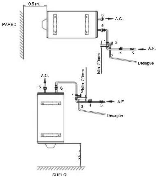
FIG.1-INSTALLACION TOMAS SUPERIORES
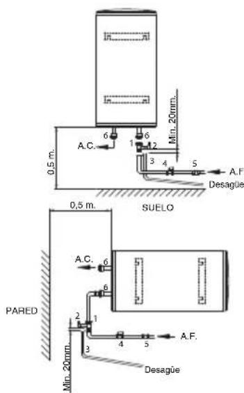
FIG.2- INSTALLACION TOMAS INFERIORES
ES
-
Safety valve
-
Easing lever (for draining)
-
Discharge pipe of the pressure relief device.
4.Shut off valve.
-
Pressure reducer: it's necessary installed after the "meter" when the pressure is more than 5kg/cm^2 .
-
Earthy plastic sleeves (supplied with the heater).
FB
m = 311
Jyll 5
(1)
(ωωω)
$$ \therefore \text {i n} 2 $$
$$ \begin{array}{l} i, j = 1, 2, \dots , - 3 \ a c c a l l 2 2 2 2 - 4 \ \therefore \lim _ {y \to 0} y = 5 \ \end{array} $$
FICHA DE PRODUCTO
10.- Annual electricity consumption
11.- Daily electricity consumption
12.- Temperature setting for the temperature controller
13. - "Smart" value "1": The information on the hot water generation energy efficiency and on the manual power or fuel consumption applies only when the intelligent control system is switched on.
14.- Weekly fue consumption with smart control
15.- Weekly fue consumption withou smart control
16.- Weekly electricity consumption with smart control
17.- Weekly electricity consumption without smart control
18.- Option to only operate during low-demand periods.
19.- Capacity
20.- Mixed water at 40^