
CB-50ECO - Boiler FAGOR - Free user manual and instructions
Find the device manual for free CB-50ECO FAGOR in PDF.


| Product type | Wall-mounted gas condensing boiler |
| Brand | Fagor |
| Model | CB-50ECO |
| Dimensions (H x W x D) | 740 x 440 x 340 mm |
| Weight | Approximately 35 kg |
| Power supply | Natural gas (G20) or propane (G31) - Electricity: 230 V / 50 Hz |
| Nominal thermal output | 24 kW (heating) - 24 kW (DHW) |
| Efficiency | Up to 93 % (PCS) |
| Main functions | Central heating and instantaneous domestic hot water production |
| Ignition type | Electronic ignition |
| Energy class | A (according to directive 92/42/EEC) |
| Maintenance and cleaning | Annual mandatory maintenance by a qualified professional |
| Safety | Overheat protection, frost protection, pressure limiter, flame detection |
| Spare parts and repairability | Parts available from Fagor after-sales service |
| Repairability index | Not communicated |
| Warranty | 2 years (parts and labor) |
| Standards | CE, NF |
| Operating temperature | Heating: 30-80 °C - DHW: 30-60 °C |
| Operating pressure | Heating: 1-3 bar - DHW: max 10 bar |
Frequently Asked Questions - CB-50ECO FAGOR
User questions about CB-50ECO FAGOR
0 question about this device. Answer the ones you know or ask your own.
Ask a new question about this device
Download the instructions for your Boiler in PDF format for free! Find your manual CB-50ECO - FAGOR and take your electronic device back in hand. On this page are published all the documents necessary for the use of your device. CB-50ECO by FAGOR.
USER MANUAL CB-50ECO FAGOR
natural_image
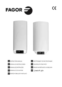
White portable water heater with a curved white line on top and a black control panel at the bottom (no visible text or symbols)
natural_image
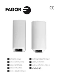
White water heater with a digital display unit at the bottom (no visible text or symbols on the body)EN INSTRUCTION MANUAL
CONGRATULATIONS. You have decided to acquire an electric water heater from FAGOR. We are a prestigious brand and our top priority is fulfilling the needs of our customers, solving them in advance via our innovative state of the art products. Our specialists have carefully manufactured and inspected all our FAGOR electric water heaters in order to provide an ideal response to their needs.
Thank you for the confidence placed in us.
The correct operation of a water heater does not only depend on the quality of the product, but also on its correct installation by a trained professional.
Read this manual carefully before installing and using your water heater in order to achieve its highest performance and extend its life cycle. Keep this manual for future use.
SAFETY AND GENERAL WARNINGS
- The installation and first use must be performed according to these instructions and only by trained professionals. (See the installation section).
- FAGOR water heaters are manufactured and tested according to current regulations.
- This device can be used by children age 8 and older, by physically, sensory or mentally handicapped persons, or persons without proper experience or knowledge, if they have received appropriate supervision or training regarding the safe use of the device and understand the dangers involved. Children should not play with the device. Cleaning and maintenance of the device should not be performed by unsupervised children.
- If the power cable is damaged it must be replaced by the manufacturer, its post-sales department or similarly trained personnel in order to prevent any risks.
- The pressure limiter device must be used often in order to remove lime deposits and verify it is not blocked.
- The water heater does not need any specific maintenance. Before cleaning the device, disconnect it. Scrubbing it with a smooth cloth or moist sponge is enough. Do not use abrasive materials or detergents.
ENVIRONMENT
Legislations and regulations for the protection of the environment are strictly observed (2002/96/EC guideline on electric and electronic waste).
INFORMATION FOR THE CORRECT MANAGEMENT OF RESIDUES FROM ELECTRIC AND ELECTRONIC DEVICES
At the end of its life cycle, it should not be disposed of mixed with general wastes.
It can be delivered, without any cost, to specific waste collection centers, designed by local administrations, or to suppliers that provide this service.

Disposing of the electric device separately serves to prevent possible harmful consequences for environment and health derived from an incorrect disposal, and permits a correct treatment and recycling of its materials, which result in important energy and resources savings.
For further information, contact the local authorities or the store where you acquired the product.
MALFUNCTIONS OR BREAKDOWN
If your water heater presents any malfunctions, immediately disconnect the device from the electrical power supply. Report to the Technical Assistance Service.
In order to facilitate the tasks of the Technical Assistance Service, please provide the following data:
- Heater model.
– Series number.
– Purchase date.
– Description of the problem.
– Address and phone number.
– Full name of the contact person.
INSTALLATION
ACCESORIES
This electric water heater includes the basic installation elements which are found in the packaging, i.e.:
– Insulating bushing for pipes.
- Safety valve.
The accessories are located within the packaging.
WALL MOUNTING PROCEDURE
Both the wall and the screws and Rawl-plugs should be capable of withstanding the weight produced by a totally full heater. In case of low thickness walls, the wall should be reinforced.
NOTE.- The placement of the heater must allow access to the supply cable.
LOCATION
The installation procedure is greatly facilitated by being able to locate the unit horizontally or vertically anywhere in the house.
It is advisable, however, to situate the unit as close as possible to where the hot water is to be used as pipe length reduction allows water temperature losses to be prevented.
A minimum 0,5 m space should be left underneath the pipe outlet for servicing.
As shown in the drawing 1, when installed horizontally, the input and output pipes must be located on the left.
Should the unit be close to a wall, leave the minimum recommended space for maintenance and servicing operations.
Don't install the heater with its wall mounts against the floor nor on a horizontal plane.
HYDRAULIC INSTALATION
NOTE FOR INSTALLERS: the insulating sleeves found inside the packaging, must be located on the inlet/outlet pipes, using teflon on the screw of the pipes. Tightening torque for sleeves: 3.5Kg/m.
Before proceeding to the hydraulic connexion, please rinse the connecting pipe in the order to avoid filth from entering inside the electric water heater.
Install the water heater according to the diagrams in figure 1
a) The safety valve supplied with the heater MUST BE INSTALLED on the cold water input pipe.
No other hydraulic accessory can be installed between the safety valve and the cold water inlet pipe.
The outlet of the safety valve must be connected to a drain, whose diameter should be at least identical to inlet pipe. The inclination must be continuous and open, keeping a minimum distance of 20mm., as shown in Figure 1. This pipe must be installed in an environment where freeze is not possible and with a downward slope. Water expands when heated, leaking (at leats a 3% per heating cycle). Do not worry, this is a standard phenomenon.
To empty the heater, operate the safety group hoisting the lever as shown on figure 2. We should act on said lever periodically to prevent it locks and check for proper operation.
b) If the water-supply pressure exceeds 5 bars, a type-approved reducing valve (between 3 or 4 bars) must be installed.
c) In case of plastic piping in the system, please take into account pressure and temperature conditions. Maximum pressure 9 bars and 70°C maximum temperature in standard conditions or 100°C in abnormal conditions when the safety thermostat cuts the energy supply.
ELECTRIC INSTALLATION
All storage water heaters are of 230V AC. Before connecting make sure that the mains supply and unit input features coincide.
The heater's installation procedure is totally straightforward and only requires that Low Voltage Electronic Regulations be met.
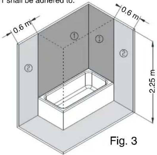
For installations in bathrooms and toilets Regulation IEC 60364-7-701 shall be adhered to.
VOLUME OF PROHIBITION: Zone 1 defined in figure 3.
No switches, sockets or lighting fixtures will be installed.
VOLUME OF PROTECTION: Zone 2 defined in figure 3.
No switches will be installed, however safety sockets or sockets protected by a 30 mA circuit breaker may be installed.
The boiler should be installed outside the VOLUME OF PROHIBITION, in order to prevent water reaching the inside of the appliance. If the boiler has no plug, electrical power should be supplied through a bipolar switch with contact openings of at least 3 mm. The installation should be protected with fuses of a calibre corresponding to the absorbed current. An earth connection should be included in every electrical installation. To make this connection, the boiler plug is provided with the appropriate contact, therefore it is enough for the base of the plug to correspond to that supplied with the appliance.
If there is no regulatory "EARTH", we recommend the installation of a ≤30 mA differential switch.
This appliance complies with the regulation on Radio-electric Disruption and interferences. WARNING: always service the appliance with official aftersales, included the plug.
CONTROL PANEL

2.- Button for reducing selected temperature
3.- Button for increasing selected temperature
4.- Display: Indicates water temperature
5.- ECO LED: indicates ECO mode is on
6.- Resistor 1 LED: indicates resistor is on
7.- Resistor 2 LED: indicates 2nd resistor is on (for models with power mode)
8.- PROTEK LED: indicates that the corrosion protection and overheat when empty protection are on (for models with electronic anode)
9.- ECO button
START UP
Filling up. Open the shutoff cock as soon as the heater has been installed. Open the hot water taps. Water appears as soon as the unit fills up completely. Close the taps and check the system for leaks.
Don't connect the heater to the power mains if uncertain as to whether it is full or not.
Electric connection: Plug into the main socket and switch on the main power switch so that the appliance is powered. After switching on the main power switch, press button (1) to switch on the display (4) that indicates the water heater temperature. When a certain quantity of hot water is used, the thermostat connects the heating element again.
Temperature selection: Using buttons (2) to decrease the temperature and (3) to increase the temperature, select the required temperature shown on the display (4). The temperature range is 30 eC to 80 eC. LED (6) and (7) indicate that the electric resistors are on.
The water heater should be permanently switched on as the control system will ensure that it only operates as required to maintain the selected temperature and any insignificant heat losses are guaranteed by the polyurethane foam heat insulation.
In the event of a power failure the water heater stores the settings prior to the power cut and therefore it is not necessary to press the Start-Stop button (1) again for the water heater to operate.
How to empty the unit. The heater should be fully drained if left unused for extended periods or if subject to freezing hazards where installed. This can be done by means of the safety valve.
Always remember to:
– Cut-off the power supply.
- Shut-off the input cock.
- Open the hot water tap..
FEATURES
ANTI LEGIONELLA (AL) SYSTEM
This is a preventive system activated by default at the factory to prevent the spread of bacteria such as legionella.
When the water temperature falls below 70^ for 30 days, the water heater runs a heating cycle until a temperature of 70 ^ C is reached regardless of the selected temperature setting.
This preventive system can be switched on or off by the user in accordance with that shown in the following table:
| 1- Feature 2- Access. | 3- Switching feature on / off. | 4- What is displayed. | 5- Exit the configuration. | |
| Anti-legionella | Press "+" and "-" together for 3 seconds | Press "+" or "-" | On 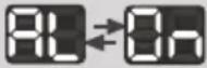 | Automatically after 5 seconds |
Off 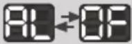 | ||||
POWER MODE (Square water heaters)
The water heater can be configured to operate with one or two resistors or a combination of both options. The user can select one of the following modes:
- Mono power mode (P1): When heating is required, the water heater activates one of the two resistors alternately, thereby increasing the service life of the components.
- Dual power mode (P2): When heating is required, the water heater activates both resistors at the same time, thereby providing a rapid response to reach maximum power.
- Automatic mode (Au): This mode combines the advantages of the above modes: a longer service life at maximum power. When the water heater detects a significant consumption of hot water, it immediately activates the maximum power by using all the resistors for the heating. When the consumption is low or if the water temperature is slightly lower than the setting temperature, the water heater activates each of the two resistors alternately.
The user can select the required mode by following the steps given in the table below:
| 1- Feature 2- Access. | 3- Switching feature on / off. | 4- What is displayed. | 5- Exit the configuration. | |
| Power management | Press "Eco" and "+" together for 3 seconds | Press "+" or "-" | Mono power  | Automatically after 5 seconds |
Dual power→ | ||||
Automatic 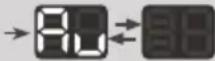 | ||||
Depending on the model, the water heater is fitted with one of the following anti-corrosion protections:
a) Protek: this is an exclusive modulating electronic system which, in combination with the titanium anode, sets the water heater power at values within the ideal corrosion protection zone, thereby guaranteeing the maximum service life of the water heater tank.
The correct operation of the Protek requires that the water heater is permanently connected to a 230 VAC electric power supply, even when the water heater is not operating.
The correct operation of the Protek is indicated by LED (8) which remains permanently lit.
Battery Kit (optional): models equipped with the Protek system can be converted into water heaters for use with the night tariff (or time discriminating tariff), by fitting a Battery Kit (installed by a professional technician). The battery guarantees the power supply to the Protek in the event of a power failure lasting up to 24 hours. In this case the correct operation of the Protek is indicated by LED (8) which flashes.
In the event of a fault in the Protek system, LED (8) switches off completely and the water heater triggers the corresponding fault code on the display (4).
b) Magnesium anode: this is a protection system for the water heater tank using a sacrificial magnesium anode attached to the water heater flange.
VACATION MODE
In the event of a temporary absence or journey, the "vacation mode" is activated by pressing the button (without disconnecting the water heater from the main power supply or switching off the main power supply of the house).
The water heater enters energy-saving mode by deactivating all unnecessary sources of consumption (resistors, display, LED...) and maintaining all the safety features activated (de-icing system, electronic anti-corrosion protection, self-diagnosis...)
De-icing system: The water heater is protected against low temperatures. Whenever the temperature of the accumulated water is less than 5 °C, the resistors will automatically start operating until a temperature of 10 °C is reached. While the de-icing system is on the message 📄 is displayed cyclically.
ECO SMART FUNCTION
The ECO function allows the temperature setting to be automatically adjusted according to the weekly habits of the user. It is activated by pressing the ECO button, or in models without ECO button, the temperature is increased or decreased (using the +/ - buttons) until a value between 65 and 66 °C is shown on the display (4). When the ECO function is on, the “ECO” LED lights up.
INFORMATION FOR THE TECHNICAL SERVICE ELECTRICAL CIRCUIT AND CONNECTIONS DIAGRAM

ELECTRIC CONNECTIONS BY MODEL
| MODELS | Capacities (litres) | Electronic probe | Resistors | Power cable | Electronic anode | Rechargeable battery |
| CB-30 ECO | 30 | X | X | |||
| CB-30C ECO | 30 | Op | ||||
| CB-50 ECO | 50 | Op | ||||
| CB-80 ECO | 75 | Op | ||||
| CB-100 ECO | 100 | Op | ||||
| CB-150 ECO | 150 | Op | ||||
| RB-30 ECO | 30 | X | X | |||
| RB-30C ECO | 30 | X | X | |||
| RB-50 ECO | 50 | X | X | |||
| RB-80 ECO | 75 | X | X | |||
| RB-100 ECO | 100 | X | X | |||
| RB-150 ECO | 150 | X | X |

Includes this connection
X Does not have this connection
Op Not fitted as standard (optional)
MAINTENANCE
The water heater does not need any specific maintenance. Before cleaning the device, disconnect it. Scrubbing it with a smooth cloth or moist sponge is enough. Do not use abrasive materials or detergents.
Overheating due to a fault in the temperature control is protected by the electronic card, which disconnects the two phases and leaves the water heater resistors without a power supply.
In this case, the Technical Service should be called to repair the fault.
THE MANUFACTURER reserves the right to modify the characteristics and specifications of all products without prion notice.
DIAGNOSIS AND REPAIRS
A) Faults:
The water heater is equipped with a safety system which blocks the appliance if any operating faults are detected, and the corresponding fault code is displayed.
Some of these blocks are automatically reset, while others are safety blocks requiring the manual resetting of the "Safety Reset button" found in the electronic circuit.
The possible faults are listed in the following table:
| FAULT(Display) | PROBLEM | SOLUTIONS |
| E1 Water | heater empty | Model with Protek: Fill water heater and presModels without Protek: Call the technical service. |
| E2 | Electronic temperature probe not connected or faulty | Call the technical service. |
| E3 Faulty | anode• Call the technical service. | |
| E5 Circuit | • Call the technical service. | |
| E7 Circuit | Call the technical service. | |
| E8 | Overheating (94 °C) | Check that the water input temperature is less than 80 °CIf the fault persists, call the technical service. |
| E9 | Temperature probe faulty | Call the technical service. |
B) Alarms:
When there is a fault in the operation that does not affect safety, the water heater continues to operate, while at the same time indicating the fault type on the display.
The possible alarms are indicated on the following table:
| ALARM (Display) | PROBLEM | SOLUTIONS |
| "Bt" message every 10 seconds | Battery not foundBattery flat | Call the technical service. |
| "rE" message every 10 seconds | Faulty resistor | Call the technical service. |
SYSTÈME ANTI-LÉGIONELLE (AL)
HYDRAULICKÁ INSTALACE
ELEKTRICKÁ INSTALACE
HYDRAULICKÁ INŠTALÁCIA
natural_image
Pure technical line drawing of a mechanical assembly without any text, numbers, or symbolsDETALLE ENCLAVAMIENTO

ESQUEMA DE INSTALACION -FIG. 1-

ES
1. Grupo de seguridad hidráulica (suministrada con el calentador).
2. Mando grifo vaciado
3. Desagüe conducido.
4. Llave de paso.
5. Reductor de presión: Es necesario colocarlo después del con-tador, en la entrada de la vivienda (nunca cerca del calentador cuando la presión es superior a 5 Kg/cm²).
6. Manguitos aislantes (suministrados con el calentador).
PT
1. Grupo de segurança hidráulica (fornecida com ol termo).
2. Comando da válvula de drenagem.
3. Esgoto canalizado.
4. Válvula de corte
5. Redutor de pressão: E necessário colocá-lo depois do contador, na entrada da habitação (nunca próximo do termo quando a pressão seja superior a 5 Kg/cm²).
6. Casquilhos isolantes (fomecidos com o termo).
EN
1. Safety valve.
2. Easing lever (for draining).
3. Discharge pipe of the pressure relief device.
4. Shut off valve.
5. Pressure reducer: it's necessary installed after the "meter" when the pressure is more then 5 kg/cm².
6. Earthed plastic sleeves (supplied with the heater).
FR
1. Groupe de sécurité hydraulique (fourni avec l'appareil de chauffage).
2. Commandement vider robinet.
3. Égoutter entraînée.
4. Robinet
5. Réducteur de pression: Il est nécessaire de placer après-compteur à l'entrée de la maison (jamais près du chauffage lorsque la pression est supérieure à 5 kg/cm²).
6. Manchons isolants (fourni avec l'appareil de chauffage).
CZ
1. Bezpečnostní ventil.
2. Výpustní páka.
3. Výpustní trubka tlakového pojistného zařízení.
4. Uzaviraci ventil.
5. omezovač tlaku: musí se nainstalovat za vodoměr, když je tlak v síti vyšší než 5 kg/cm²
6. Uzemněné plastové izolační manžety (dodávané s boilerem).
RU
1. Предохранительный клапан (поставляется с водонагревателем)
2. Водослив
3. Ручка крана для опорожнения
4. Запорный кран
5. Клапан понижения давления. Всегда размещайте клапан на расстоянии не ближе одного метра до входа в водонагреватель, если давление выше 5 кг/см²
6. Изоляционные втулки (поставляются с водонагревателем)
HU
1. Biztonsági szelep.
2. Vyprazdňováni kohoutku.
3. Leürítő csap.
4. Leeresztő cső.
5. nyomáscsökkentő: mindig a mérő mögé kell elhelyezni, ha a nyomás 5 kg/cm² nél nagyobb.
6. Földelt müanyag szigetelő gyűrűk (a készülékhez mellékelve).
SK
1. Bezpečnostný ventil.
2. Uvolňovacia páka (pre vypúštanie)
3. Vypúšťacie potrubie pre úvoľnenie tlaku v zariadení
4. Vypústací ventil.
5. Tlakový redukčný ventil: musí byť namontovaný v prípade, že je tlak vyšší ako 5 kg/cm².
6. Uzemnené plastové manžety (dodávajú sa s ohrievačom).
AR
natural_image
Technical diagram showing two mechanical assembly configurations labeled 1 and 2 (no text or symbols present)ES
1. Posición de trabajo
2. Posición de vaciado
PT
1. Posição de trabalho
2. Posição de esvaziar
EN
1. Working position
2. Emptying position
FR
1. Position de travail
2. Position de vidange
CZ
1. Provozní poloha
2. Poloha vyprázdnění
RU
1. Рабочее положение
2. Положение слива
HU
1. Müködés
2. Leeresztés
SK
1. Pracovná pozícia
2. Pozicle vypúštania
AR
وصعية التفريع
.2. و supportive الت “[.”
1.- Brand name
2.- Models
3.- Emission of nitrogen oxides
4.- Sound power level
5.- Hot water generation: Specified load profile
6.- Hot water generation: Energy-efficiency class
7.- Hot water generation: Energy-efficiency
8.- Annual fuel consumption
9.- Daily fuel consumption
10.- Annual electricity consumption
11.- Daily electricity consumption
12.- Temperature setting for the temperature controller
13.- "Smart" value "1": The information on the hot water generation energy efficiency and on the manual power or fuel consumption applies only whe the intelligent control system is switched on.
14.- Weekly fue consumption with smart control
15.- Weekly fue consumption without smart control
16.- Weekly electricity consumption with smart control
17.- Weekly electricity consumption without smart control
18.- Option to only operate during low-demand periods.
19.- Capacity
20.- Mixed water at 40°C.
FR



- SAFETY AND GENERAL WARNINGS
- ENVIRONMENT
- INFORMATION FOR THE CORRECT MANAGEMENT OF RESIDUES FROM ELECTRIC AND ELECTRONIC DEVICES
- MALFUNCTIONS OR BREAKDOWN
- INSTALLATION
- ACCESORIES
- WALL MOUNTING PROCEDURE
- LOCATION
- HYDRAULIC INSTALATION
- ELECTRIC INSTALLATION
- START UP
- FEATURES
- ANTI LEGIONELLA (AL) SYSTEM
- POWER MODE (Square water heaters)
- VACATION MODE
- ECO SMART FUNCTION
- INFORMATION FOR THE TECHNICAL SERVICE ELECTRICAL CIRCUIT AND CONNECTIONS DIAGRAM
- MAINTENANCE
- DIAGNOSIS AND REPAIRS
- A) Faults:
- B) Alarms:
- SYSTÈME ANTI-LÉGIONELLE (AL)
- HYDRAULICKÁ INSTALACE
- ELEKTRICKÁ INSTALACE
- HYDRAULICKÁ INŠTALÁCIA
- FR
Brand : FAGOR
Model : CB-50ECO
Category : Boiler