
CB200 I - Boiler FAGOR - Free user manual and instructions
Find the device manual for free CB200 I FAGOR in PDF.
| Product type | Electric water heater (boiler) |
| Brand | Fagor |
| Model | CB200 I |
| Capacity | 200 liters |
| Power supply | 230 V AC |
| Temperature range | 30 °C to 70 °C (adjustable) |
| Installation position | Vertical or horizontal |
| Hydraulic connection | Cold water inlet with safety valve supplied |
| Electrical protection | Residual current circuit breaker ≤ 30 mA recommended |
| Main functions | Water heating, adjustable thermostat, energy saving mode (55 °C) |
| Safety | Safety valve, safety thermostat, earthing, automatic shut-off in case of overheating |
| Maintenance and cleaning | Clean with a soft cloth or damp sponge, without abrasives or detergents |
| Spare parts and repairability | Contact Fagor after-sales service for original parts |
| General information | Complies with WEEE directive 2002/96/EC, recycling at end of life |
Frequently Asked Questions - CB200 I FAGOR
User questions about CB200 I FAGOR
0 question about this device. Answer the ones you know or ask your own.
Ask a new question about this device
Download the instructions for your Boiler in PDF format for free! Find your manual CB200 I - FAGOR and take your electronic device back in hand. On this page are published all the documents necessary for the use of your device. CB200 I by FAGOR.
USER MANUAL CB200 I FAGOR
natural_image
White water heater with a curved white line and control knob (no visible text or symbols)EN INSTRUCTION MANUAL
SAFETY AND GENERAL WARNINGS
- The installation and first use must be performed according to these instructions and only by trained professionals. (See the installation section).
- FAGOR water heaters are manufactured and tested according to current regulations.
- This device can be used by children age 8 and older, by physically, sensory or mentally handicapped persons, or persons without proper experience or knowledge, if they have received appropriate supervision or training regarding the safe use of the device and understand the dangers involved. Children should not play with the device. Cleaning and maintenance of the device should not be performed by unsupervised children.
- If the power cable is damaged it must be replaced by the manufacturer, its post-sales department or similarly trained personnel in order to prevent any risks.
- The pressure limiter device must be used often in order to remove lime deposits and verify it is not blocked.
- The water heater does not need any specific maintenance. Before cleaning the device, disconnect it. Scrubbing it with a smooth cloth or moist sponge is enough. Do not use abrasive materials or detergents.
ENVIRONMENT
Legislations and regulations for the protection of the environment are strictly observed (2002/96/EC guideline on electric and electronic waste).
INFORMATION FOR THE CORRECT MANAGEMENT OF RESIDUES FROM ELECTRIC AND ELECTRONIC DEVICES
At the end of its life cycle, it should not be disposed of mixed with general wastes.
It can be delivered, without any cost, to specific waste collection centers, designed by local administrations, or to suppliers that provide this service.

Disposing of the electric device separately serves to prevent possible harmful consequences for environment and health derived from an incorrect disposal, and permits a correct treatment and recycling of its materials, which result in important energy and resources savings.
For further information, contact the local authorities or the store where you acquired the product.
MALFUNCTIONS OR BREAKDOWN
If your water heater presents any malfunctions, immediately disconnect the device from the electrical power supply. Report to the Technical Assistance Service.
In order to facilitate the tasks of the Technical Assistance Service, please provide the following data:
- Heater model.
– Series number.
– Purchase date.
– Description of the problem. - Address and phone number.
– Full name of the contact person.
INSTALLATION
ACCESORIES
This electric water heater includes the basic installation elements which are found in the packaging, i.e.:
– Insulating bushing for pipes.
- Safety valve.
The accessories are located within the packaging.
WALL MOUNTING PROCEDURE
Both the wall and the screws and Rawl-plugs should be capable of withstanding the weight produced by a totally full heater. In case of low thickness walls, the wall should be reinforced.
NOTE.- The placement of the heater must allow access to the supply cable.
LOCATION
The installation procedure is greatly facilitated by being able to locate the unit horizontally or vertically anywhere in the house.
It is advisable, however, to situate the unit as close as possible to where the hot water is to be used as pipe length reduction allows water temperature losses to be prevented.
A minimum 0,5 m space should be left underneath the pipe outlet for servicing.
As shown in the drawing, when installed horizontally, the input and output pipes must be located on the left.
Should the unit be close to a wall, leave the minimum recommended space for maintenance and servicing operations.
Don't install the heater with its wall mounts against the floor nor on a horizontal plane.
HYDRAULIC INSTALATION
NOTE FOR INSTALLERS: the insulating sleeves found inside the packaging, must be located on the inlet/outlet pipes, using teflon on the screw of the pipes. Tightening torque for sleeves: 3.5Kg/m.
Before proceeding to the hydraulic connexion, please rinse the connecting pipe in the order to avoid filth from entering inside the electric water heater.
Install the water heater according to the diagrams in figure 1
a) The safety valve supplied with the heater MUST BE INSTALLED on the cold water input pipe.
No other hydraulic accessory can be installed between the safety valve and the cold water inlet pipe.
The outlet of the safety valve must be connected to a drain, whose diameter should be at least identical to inlet pipe. The inclination must be continuous and open, keeping a minimum distance of 20mm., as shown in Figure 1. This pipe must be installed in an environment where freeze is not possible and with a downward slope. Water expands when heated, leaking (at leats a 3% per heating cycle). Do not worry, this is a standard phenomenon.
To empty the heater, operate the safety group hoisting the lever as shown on figure 2. We should act on said lever periodically to prevent it locks and check for proper operation.
b) If the water-supply pressure exceeds 5 bars, a type-approved reducing valve (between 3 or 4 bars) must be installed. c) In case of plastic piping in the system, please take into account pressure and temperature conditions. Maximum pressure 9 bars and 70°C maximum temperature in standard conditions or 100°C in abnormal conditions when the safety thermostat cuts the energy supply.
ELECTRIC INSTALLATION
All storage water heaters are of 230V AC. Before connecting make sure that the mains supply and unit input features coincide.
The heater's installation procedure is totally straightforward and only requires that Low Voltage Electronic Regulations be met.
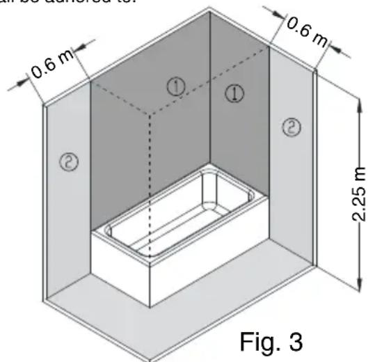
For installations in bathrooms and toilets Regulation IEC 60364-7-701 shall be adhered to.
VOLUME OF PROHIBITION: Zone 1 defined in figure 3.
No switches, sockets or lighting fixtures will be installed.
VOLUME OF PROTECTION: Zone 2 defined in figure 3.
No switches will be installed, however safety sockets or sockets protected by a 30 mA circuit breaker may be installed.
The boiler should be installed outside the VOLUME OF PROHIBITION, in order to prevent water reaching the inside of the appliance. If the boiler has no plug, electrical power should be supplied through a bipolar switch with contact openings of at least 3 mm.
The installation should be protected with fuses of a calibre corresponding to the absorbed current. An earth connection should be included in every electrical installation. To make this connection, the boiler plug is provided with the appropriate contact, therefore it is enough for the base of the plug to correspond to that supplied with the appliance.
If there is no regulatory "EARTH", we recommend the installation of a ≤30 mA differential switch.
This appliance complies with the regulation on Radio-electric Disruption and interferences.
WARNING: always service the appliance with official aftersales, included the plug.
USE
START UP
Filling up. Open the shutoff cock as soon as the heater has been installed. Open the hot water taps. Water appears as soon as the unit fills up completely. Close the taps and check the system for leaks.
Don't connect the heater to the power mains if uncertain as to whether it is full or not.
Electric Connection Plug into the mains and press the main power input switch. A light flashes on when the heating element is activated (on some models). The thermostat re-connects the heating element after a certain amount of water has been used.
Adjustment of water temperature. Models with a temperature regulation remote control allow the user to adjust the temperature of hot water within a range from 30^ C (minimum temperature) and 70^ C (maximum temperature).
In models without a temperature regulation remote control the thermostat has a standard temperature of 70°C.
Position E. (Energy saving). The water reaches a temperature of around 55^ C. In this position, heat loss is minimal and limescale deposits are almost nonexistent.
It is advisable to have the heater plugged into the mains permanently as the thermostat will only activate the unit whenever it becomes necessary to maintain the selected temperature setting. The expanded polyurethane foaming will neutralize any potential heat loss.
How to empty the unit. The heater should be fully drained if left unused for extended periods or if subject to freezing hazards where installed. This can be done by means of the safety valve.
Always remember to:
HYDRAULICKÁ INSTALACE
ELEKTRICKÁ INSTALACE
HYDRAULICKÁ INŠTALÁCIA
This device complies with the requirements of the 2014/35/EU and 2014/30/EU guidelines.
| 1.- RANGE | 2.- CAP.(L) | 3.- POWER (W)230V | 4.- CONSUMPTION(kW/24h - 65°C) | 5.- DIMENSIONS (mm) | 6.- WEIGHT(Kg) | ||||||||||
| A | B | C | D | E | F | G | H | I | J | K | |||||
| CB-30 I | 30 1.600 | 0,6 160 120 58 | 3 736 284 -- 320 323 | 307 | 7 | 32 | 15,5 | ||||||||
| CB-50 I | 50 1.600 | 0,8 160 120 | - 812 340 435 200 3 | 375 | 395 | 375 | 8 | 2 20,5 | |||||||
| CB-75 I | 75 | 900/1.800 | 0,84 | 230 | 175 | - | 745 | 300 | 280 | 250 | 489 | 516 | 489 | 748 | 28 |
| CB-100 I | 100 | 900/1.800 | 1,06 | 230 | 175 | - | 912 | 300 | 435 | 250 | 489 | 516 | 489 | 915 | 32,5 |
| CB-150 I | 150 | 1.200/2.400 | 1,51 | 230 | 175 | - | 1.250 | 300 | 790 | 250 | 489 | 516 | 489 | 1.253 | 43 |
| CB-200 I | 200 | 1.200/2.400 | 1,8 | 230 | 175 | - | 1.581 | 440 | 790 | 250 | 489 | 516 | 489 | 1.589 | 53 |


ES
natural_image
Diagram of a pipe system inside a cabinet, showing internal flow paths (no text or labels)INTERLOCKING DETAIL

INSTALLATION SCHEME -FIG. 1-

EN
- Safety valve
- Easing lever (for draining).
- Discharge pipe of the pressure relief device.
- Shut off valve.
- Pressure reducer: it's necessary installed after the "meter" when the pressure is more then 5 kg/cm².
- Earthed plastic sleeves (supplied with the heater).
ES
1.Groupes the Salama the hydrology (tong me the
1- Heating element
2- Heating pilot
3- Work. thermostat
4- Safety thermostat
ES
natural_image
Technical diagram showing two mechanical components labeled 1 and 2, with no visible text or symbols.EN
- Working position
- Emptying position
ES
PRODUCT DATA SHEET (in accordance with EU regulation no. 812/2013, 814/2013)
| 1 | Brand name | FAGOR | |||||||
| 2 | Models | CB-30 I | CB-50 I | CB-75 I | CB-100 I | CB-150 I | CB-200 I | ||
| 3 | Emission of nitrogen oxides | NOx | mg/kWh | 0 0 0 0 | 0 0 | ||||
| 4 | Sound power level L | WA | dB (A) | 15 | 15 | 15 | 15 | 15 | 15 |
| 5 | Hot water generation: Specified load profile | - | - | S | M | M | L | XL | XXL |
| 6 | Hot water generation: Energy-efficiency class | - | - | B | C | C | C | C | D |
| 7 | Hot water generation: Energy-efficiency | wh | % | 35 | 36 | 36 | 37 | 38 | 37 |
| 8 | Annual fuel consumption (*) | AFC | GJ | 0 | 0 | 0 | 0 | 0 | 0 |
| 9 | Daily fuel consumption (*) | Qfuel | GJ 0 0 0 0 0 | ||||||
| 10 | Annual electricity consumption (*) | AEC | kWh | 524 | 1413 | 1408 | 2748 | 4384 | 5826 |
| 11 | Daily electricity consumption (*) | Qelec | kWh | 2,47 | 6,61 | 6,58 | 12,77 | 20,23 | 27,13 |
| 12 | Temperature setting for the temperature controller | - | °C | 60 | 65 | 62 | 66 | 69 | 76 |
| 13 | “Smart” value “1”: The information on the hot water generation energy efficiency and on the manual power or fuel consumption applies only whe the intelligent control system is switched on. | - | - | - | - | - | - | - | - |
| 14 | Weekly Gas consumption with smart control (*) | Qfuel,week,smart | GJ | - | - | - | - | - | - |
| 15 | Weekly Gas consumption without smart control (*) | Qfuel,week | GJ | - | - | - | - | - | - |
| 16 | Weekly electricity consumption with smart control (*) | Qelec,week,smart | kWh | - | - | - | - | - | - |
| 17 | Weekly electricity consumption without smart control (*) | Qelec,week | kWh | - | - | - | - | - | - |
| 18 | Option to only operate during low-demand periods. | - | - | - | - | - | - | - | - |
| 19 | Capacity | V | I | 30 | 50 | 75 | 100 | 150 | 200 |
| 20 | Mixed water at 40 °C. | V40 | I | 41,57 | 76,07 | 103,55 | 146,28 | 254 | 377,91 |
(*) For average climatic conditions
Note: All of the data that is included in the product information was determined by applying the specifications of the relevant European directives. Differences to product information listed elsewhere may result in different test conditions.
Only the data that is contained in this product information is applicable and valid.
ES


- SAFETY AND GENERAL WARNINGS
- ENVIRONMENT
- INFORMATION FOR THE CORRECT MANAGEMENT OF RESIDUES FROM ELECTRIC AND ELECTRONIC DEVICES
- MALFUNCTIONS OR BREAKDOWN
- INSTALLATION
- ACCESORIES
- WALL MOUNTING PROCEDURE
- LOCATION
- HYDRAULIC INSTALATION
- ELECTRIC INSTALLATION
- USE
- START UP
- HYDRAULICKÁ INSTALACE
- ELEKTRICKÁ INSTALACE
- HYDRAULICKÁ INŠTALÁCIA
- ES
- EN
Brand : FAGOR
Model : CB200 I
Category : Boiler