Timemachine TM01 - Bike BMC - Free user manual and instructions
Find the device manual for free Timemachine TM01 BMC in PDF.

| Brand | BMC |
| Model | Timemachine TM01 |
| Category | Time trial / triathlon bike |
| Frame material | Carbon |
| Available frame sizes | S, M, L |
| Frame weight (estimate) | Approximately 1.2 to 1.5 kg |
| Brake type | BMC specific brakes, pad |
| Fork | Specific carbon fork (part no. 210510-210512) |
| Stem | Modular P2P system with 10° and 30° angle shims, 10mm and 20mm spacers |
| Seatpost | P2P system with specific clamp |
| Drivetrain compatibility | Mechanical Shimano, SRAM, Campagnolo; electronic Shimano Di2 |
| Power (Di2) | Shimano Di2 battery (mount supplied) |
| Position adjustment | Stack and reach adjustable via stem and saddle carriage |
| Recommended tools | 2-5 mm Allen keys, torque wrench, carbon assembly paste, Loctite red |
| Maintenance | Hand wash, no high-pressure jet; assembly paste on seatpost |
| Main torque settings | Stem: 12 Nm (shim), 2 Nm (clamp screw); Seatpost: 7.5 Nm; Brakes: 4.5 Nm |
| Spare parts | Numerous parts listed (brakes, pads, cables, etc.) |
| Warranty | Consult BMC dealer |
Frequently Asked Questions - Timemachine TM01 BMC
User questions about Timemachine TM01 BMC
0 question about this device. Answer the ones you know or ask your own.
Ask a new question about this device
Download the instructions for your Bike in PDF format for free! Find your manual Timemachine TM01 - BMC and take your electronic device back in hand. On this page are published all the documents necessary for the use of your device. Timemachine TM01 by BMC.
USER MANUAL Timemachine TM01 BMC
Owners Manual - english
CONTENTS
Owners Manual
Introduction 3
| Positioning | 5 |
| How to measure your position | 5 |
| Determine the right frame size and configuration | 8 |
| Seat post hardware position | 10 |
Frameset overview 11
Building a timemachine 13
Recommended tooling 13
Recommended procedure 14
| Frame preparation | 14 |
| Di2 specific parts | 14 |
| Parts to check | 15 |
| Brakesets | 16 |
| Assembling the brake arms | 16 |
| Brake cable routing (front) | 18 |
| Installing the pipe on front brake | 19 |
| Brake cable routing (rear) | 19 |
| Cable tension (front brake) | 21 |
| Cable tension (rear brake) | 22 |
| Brake pads setting | 22 |
| Di2 shifting | 24 |
| Cable routing | 25 |
| Handlebar specifics | 27 |
| Mechanical shifting | 27 |
| Cable routing | 27 |
| Hingefork and headset | 29 |
| Headset parts overview | 29 |
| Assembly procedure | 29 |
| P2p stem system | 31 |
| Headset parts overview | 31 |
| Assembly procedure | 32 |
| P2p seatpost | 33 |
| Seat post clamp | 33 |
Service instructions 35
| Washing your bike | 35 |
| Troubleshooting | 37 |
Introduction
BMC timemachine frame and components are designed as a system to provide a very high level of aerodynamics and riding performance. Adjustability was not in any way compromised and the timemachine offers the highest adjustment possibility ever built into a fully integrated time trial bicycle.
Adjustability being a key part of the system's performance, it is necessary to understand that most components of the frameset have been designed specifically for timemachine and their function may slightly differ from your traditional road bike "off the shelf" components.
BMC timemachine uses all the latest and most high-end technologies that can be found in bicycle manufacturing, including sharp edged and thin-walled carbon fiber composite construction, which should be treated with delicacy from the end user to prevent permanent and sometimes invisible damage.
For the reasons mentioned above, we ask you to carefully follow the instructions provided in this manual.
Incorrect mechanical operation on your bicycle could lead to serious damage, which could cause you to fall and lead to injury or death.
If you do not have the appropriate tools or experience to execute the following instructions, or if you need further information, please contact your official BMC dealer for service of your bicycle.
Positioning
A bicycle rider will only perform at his best if he is correctly positioned on his bike, especially for time trial and triathlon competitions. The following instructions are simple guidelines to help you decide which size and which stem configuration to choose in order to reach a given handlebar position. We do not in any way provide you with a fitting tool, those instructions can only help you once your position is defined. If you wish to change the position from your previous bike or if the timemachine will be your first time trial bike, we highly recommend you to visit a professional fitting expert.
Many different handlebar types and shapes are available on the market and it is not possible for BMC to guarantee accurate positioning for all of them. The handlebars provided with the TM01 complete bikes were carefully selected to offer the highest adjustment possibilities in a light, reliable and user-friendly package. Therefore we suggest you should use the original timemachine handlebars and carefully follow the instructions.
How to measure your position
In best case you already have a bike adjusted to your desired position. If there is any doubt for you regarding which position you should use, we highly recommend you to visit a professional fitting expert, who will be able to give you the required data.
To determine the right frame size, stern and seatpost hardware position, the following measurements are required:
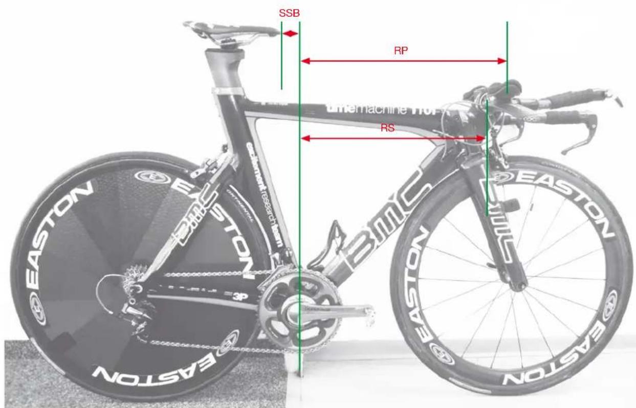
- stack (SP) and reach (RP) to the pads of your bars (Figure 1 and 2)
- stack (SS) and reach (RS) to the center of the handlebar clamp of the stem (Figure 1 and 2)
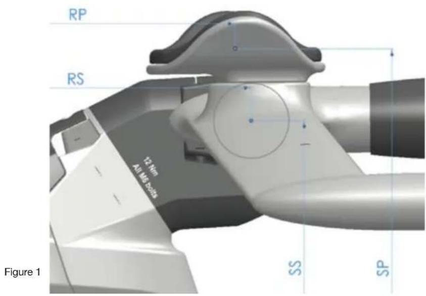
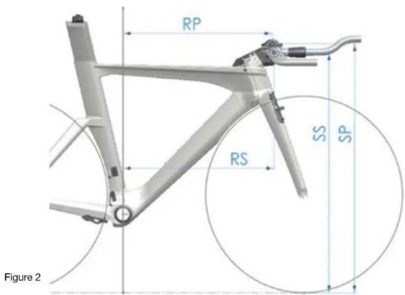
Figure 2
stack (SB) and reach (RB) of your bars (Figure 3a and b)
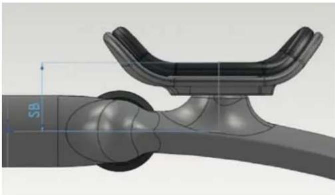
Figure 3a
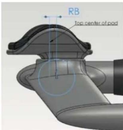
Figure 3b
- seatback to the saddle tip, valid for all Arione and SLR saddles (SB)
- vertical seat height to the top of the saddle (VSH)
- BB height (BBH)
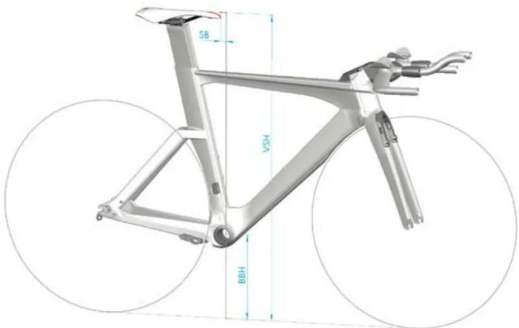
Figure 4
To take those measurements, the easiest way is to place your bike on a even, horizontal ground and lean it against a vertical edge (for example a corner of a wall, a pole or a door case) and align it so the edge is centered on the bottom bracket axle. Then follow this procedure (picture):
- Measure the vertical distance between the BB axle center and the ground (BBH).
- Measure the vertical distance between the ground and the top of the saddle (VSH).
- Measure the vertical distance from the ground to the middle and upper surface of the bar pads (SP).
-
Measure the vertical distance from the ground to the center of the handlebar clamp (SS).
-
Measure the horizontal distance from the edge your bike is leaning against to the center of the pads (RP).
- Measure the horizontal distance from the edge to the center of the handlebar clamp (RS).
- Measure the horizontal distance from the edge to the tip of your saddle (SSB) (Figure 5).
Figure 5
Example: how to measure the reach on your old bike
Determine the right frame size and stem configuration
For frame size and stem configuration, it is important to calculate the SSnew and RSnew values that your timemachine will be to. All dimensions are in millimeters!
| You intend to use: Please calculate: | |
| Your old bars on new TM | SSnew = SS - BBH RSnew = RS |
| Standard TM bars (Profile) | SSnew = SP - 60 - BBH RSnew = SP + 20 |
| Any other new bars | SSnew = SP - SB - BBH RSnew = RP + RB |
Measure SB and RB on your new bars Measure SP, RP and BBH on your old bike
Once you know your SSnew and RSnew:
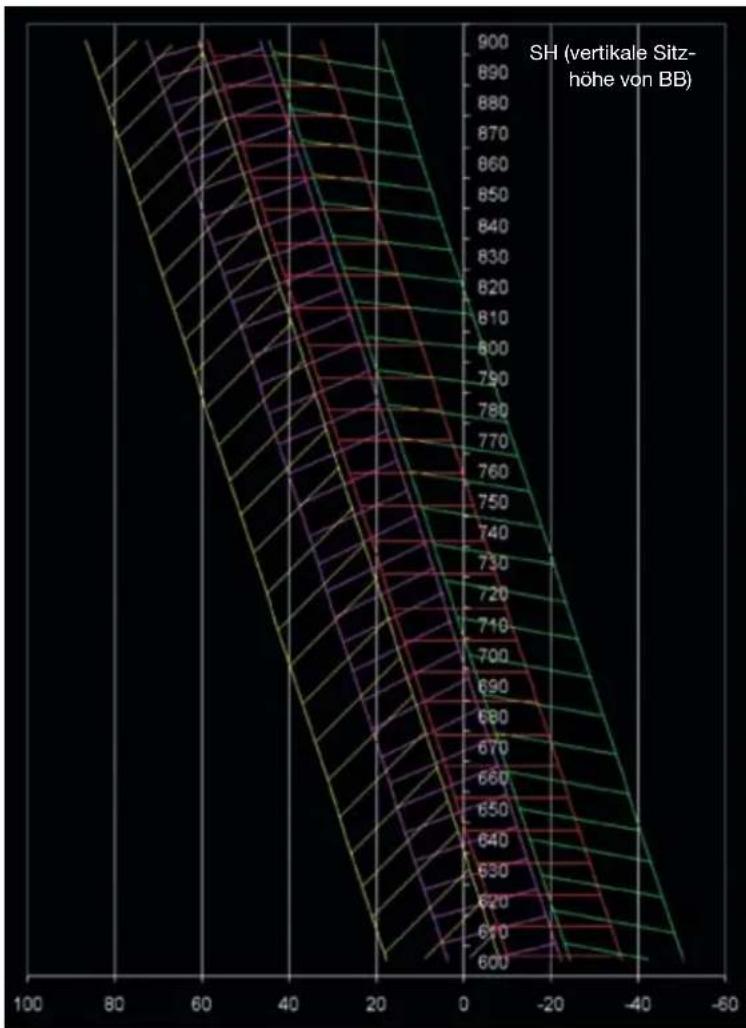
Place the SS and RS values in the chart (Figure 6) onto the horizontal and vertical.
The chart shows the various handlebar center positions you can achieve on TM01.
Check which point comes closest to the position you have calculated.
The color shows the frame size, the number is a reference to the stem configuration. All the stem configuration are listed in the second chart (Figure 7).
The Profile aero bars specified on the complete bike offer additional pad adjustment, so you will be able to reach your desired position even if the position you choose to build is some millimeters away from the calculated values.
You can use the tool on our homepage.
Stack and Reach BB to Handlebar Clamp
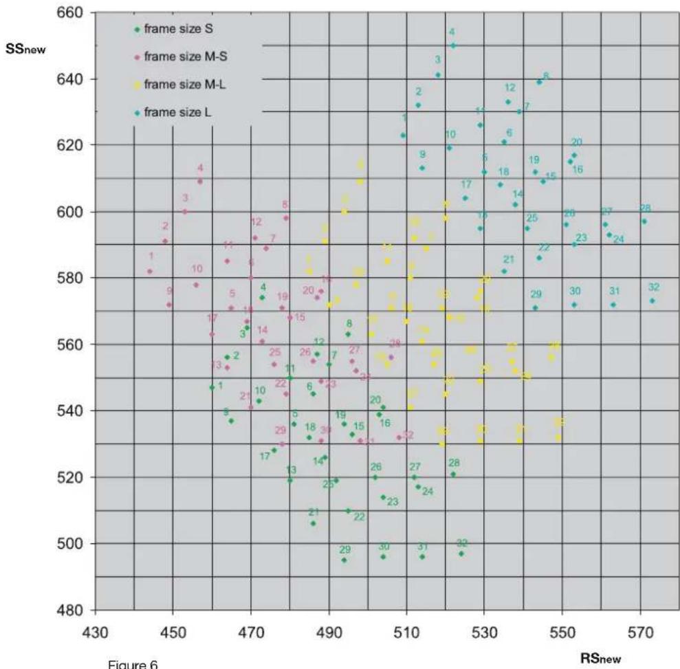
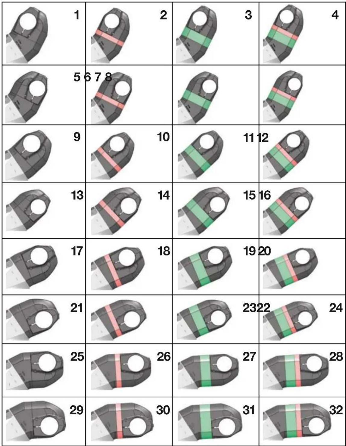
Figure 7
stem configuration
Seat post hardware position
To determine the right position of the seatpost hardware, you need to know SB and SH.
- You can measure SB on your previous bike
-Use SH = VSH - BBH
Then place the SSB and SH values in the chart below. The point thus created will fall into a colored zone. The color code will then indicate where to mount the saddle hardware.
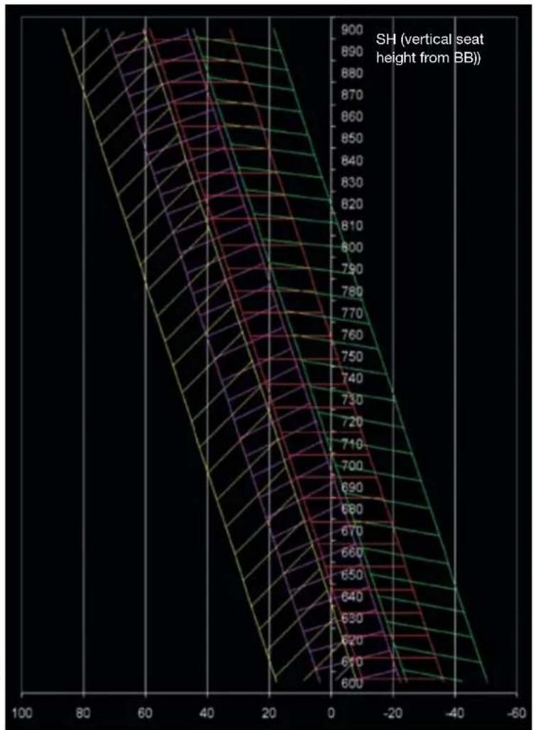
SSB (saddle seat back)

Color code
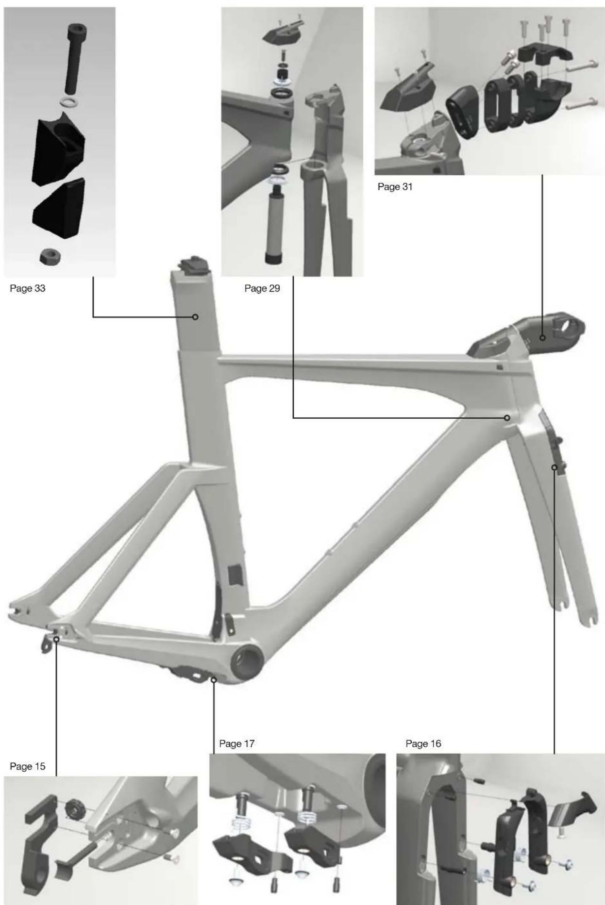
Frameset overview
Building a timemachine
A timemachine frameset or complete bike includes proprietary components such as brakes, fork, headset, stem, seat post ... For each of those components, you will find part numbers, service and assembly instructions detailed in the next chapters of this manual.
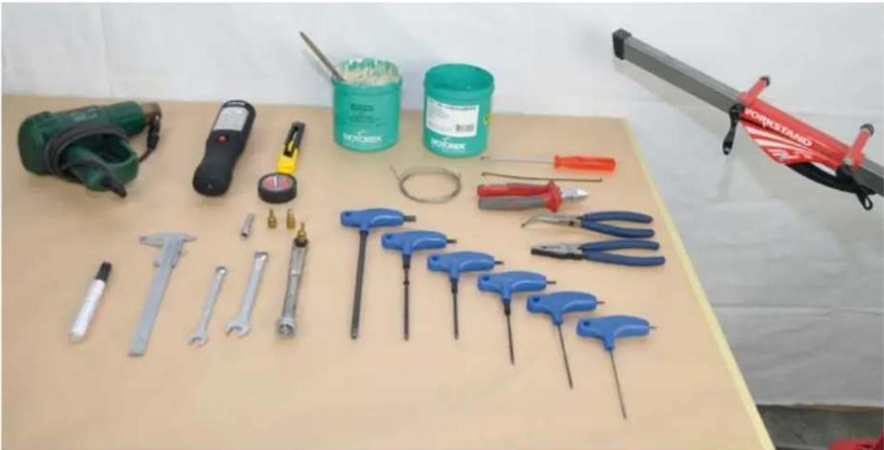
Recommended tooling
Before you start assembling, make sure you are equipped with the following tools:
-Allen keys:2mm,2.5mm,3mm,4mm,5mm
- Ratchet wrench with 8mm allen socket
- Flat wrench 9mm, 13mm
- Red Loctite 271
- Grease gun or grease brush
- Wire cutter pliers
- Long reach pliers
-A black marker pen
- Electrical tape
- 1 extra shifting cable
- Heat gun or hair dryer
- Torque wrench with 4, 5 and 8mm allen heads sockets
- Carbon friction paste
- Bike stand with fixation for frame and fork
Recommended procedure
If you are building a timemachine frameset from scratch, the most convenient way is to follow the order and the procedure described below. This is only the global procedure, all the seperate steps and recommendations are described one by one in the next pages of this manual.
Please go through all the instructions before starting the assembly of the frameset.
| 1 Frame preparation Refer to page 14, install rear wheel adjusters | ||
| 2 Mount the brake arms in frame Refer to page 15 | ||
| 3 Rear brake cable routing Refer to page 19 | ||
| 4 Shifting cable routing Non Di2: Refer to page 27 | ||
| 5 Shifting cable routing Di2: Refer to page 25 | ||
| 6 Derailleur, front and rear Refer to manufacturers instructions | ||
| 7 Fork and headset Refer to page 29 | ||
| 8 Stem Refer to page 31 | ||
| 9 Handlebars Di2: Refer to page 27 | ||
| 10 Front brake cable routing Refer to page 18 | ||
| 11 Install the pipes on brake cables Refer to pages 19 | ||
| 12 Brake cable tension front and rear Refer to pages 21 and 22 | ||
| 13 Mount wheels and brake pads | Refer to page 22 | |
| 14 Bolt on stem cover For TM01: Refer to page 36 | ||
| 15 Install top tube cable guide | Only for TM02 | |
| 16 Seat post installation | Refer to page 33 | |
| 17 Crankset | Mount the crank set once the rear brake is properly set | |
| 18 Chain | Refer to manufacturers instructions | |
| 19 Gears | Adjust the shifting, refer to manufacturers instructions | |
| 20 Bar tape | Wrap the bar tape as a final step | |
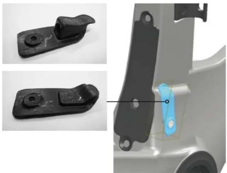
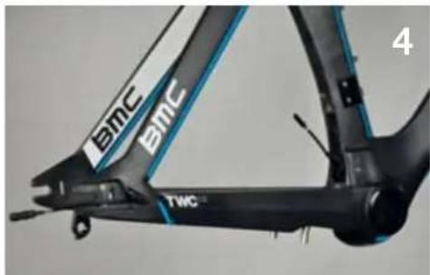
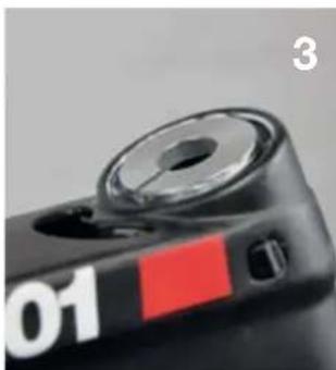
Frame preparation Di2 specific parts
When the frameset is built with Shimano Di2 groupset, replace the front derailleur cable stopper by the special cover (highlighted in blue).
FD cable stopper for mechanical groupset Part N° 210995
Cover for Di2 groupset Part N° 210996
Before assembling the frame, it is important to check
- RD hanger bolts should be well tightened with 2mm Allen key.
- Brake bosses should be mounted and tightened with red Loctite (when new, the parts are prepared at the factory).
- Timemachine frames are equipped with wheel adjusters at the rear dropout. Use the nuts to properly align the rear wheel into the frame.
| Description Part N° | ||
| 1 | Derailleur hanger & bolts 21054 | 44 |
| 2 | Axle adjuster 210545 |
- The nut should be placed so that the O-ring seal is facing towards the hub.
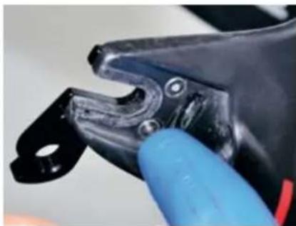
Brakesets
The timemachin is equipped with custom brakes which are only available for this specific model from BMC. The function and installation are different from what you may be used to on less integrated road bikes.
We ask you to carefully read and follow the instructions in order to avoid misuse.
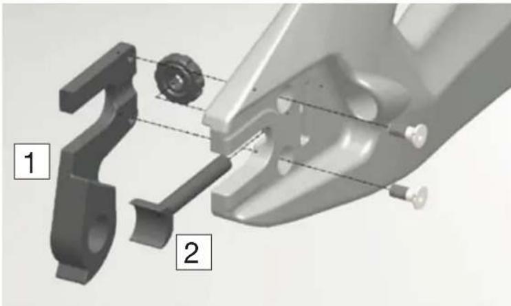
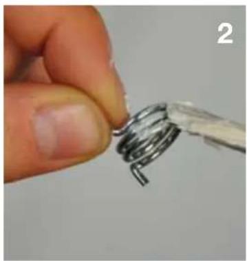
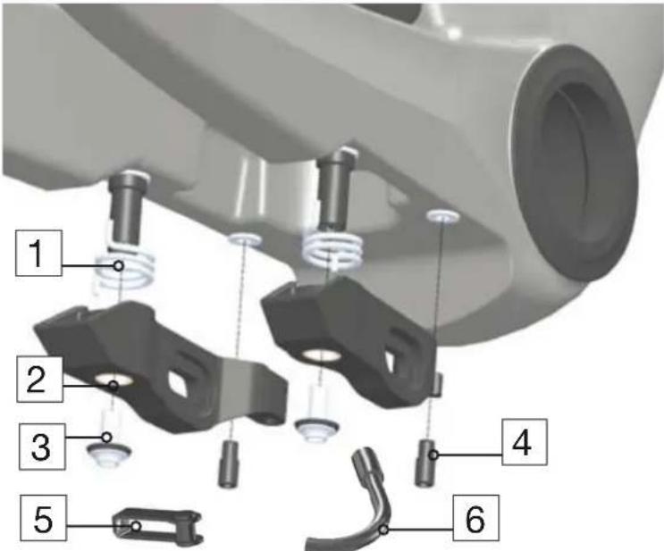
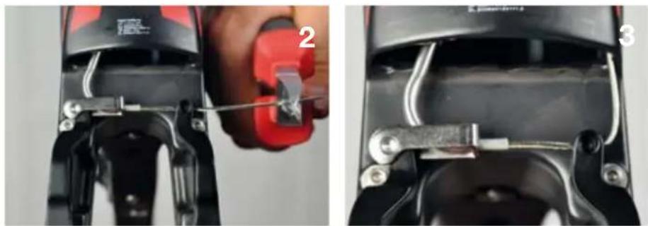
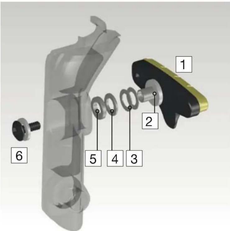
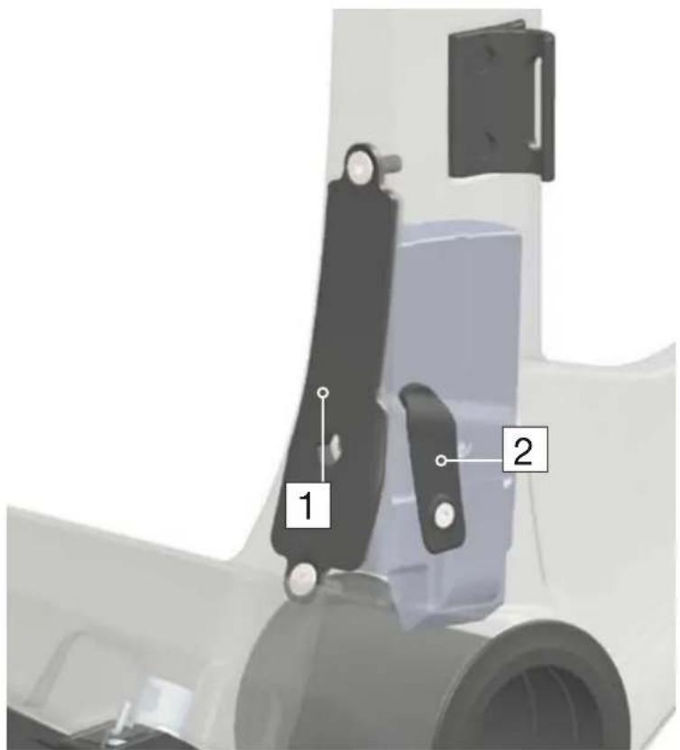
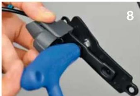
Assembling the brake arms
| Description Part N° | ||
| Brake kit (all parts) 210534 | ||
| 1 Brake arms (front) | ||
| 2 Springs | ||
| 3 Brake bosses 210541 | ||
| 4 Brake bolts | ||
| 5 Brake stoppers 210540 | ||
| 6 Brake cover 210525 | ||
| 7 Pipe 210538 | ||
| 8 Pipe holder 210539 | ||
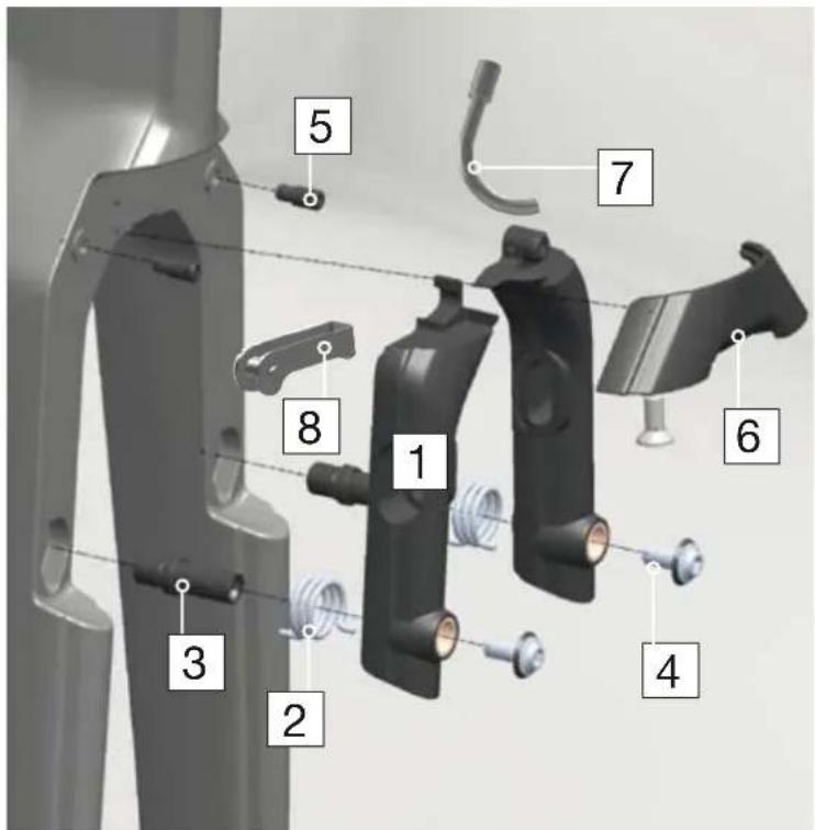
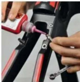
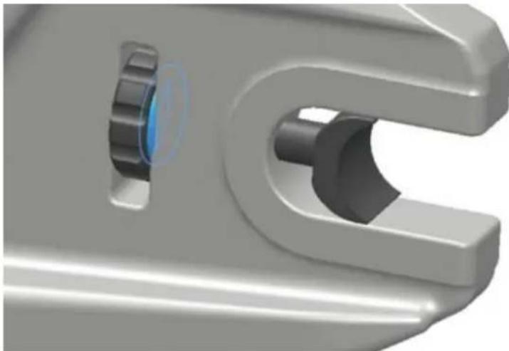
- Grease should be applied on the brake bosses and springs, and red Loctite on the brake arm bolts.
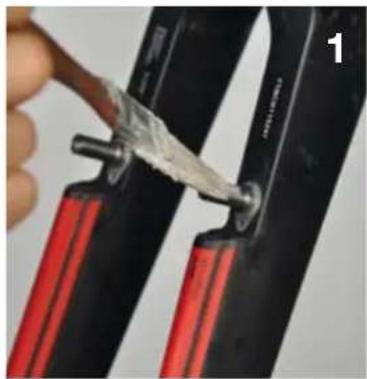
Longest extension of the spring should point out of the brake arm.
- The arms should be tightened in "open position", and then place the stoppers to maintain them in position.
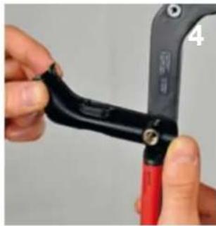
Torque 4.5 Nm
- Each brake arm should operate smoothly from the stoppers position.
- Front and rear brake arms have a different shape, but function and installation are the same.
| Description Part N° | ||
| Rear brake set 210535 | ||
| 1 Springs | ||
| 2 Brake arms | ||
| 3 Brake bolts | ||
| 4 Brake stoppers 210540 | ||
| 5 Pipe 210538 | ||
| 6 Pipe holder 210539 | ||
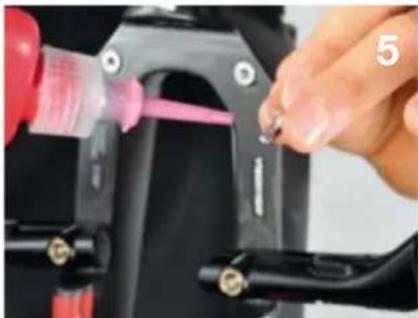
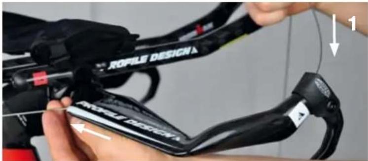
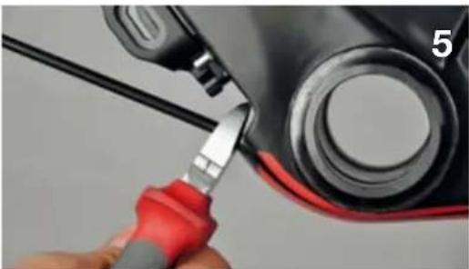
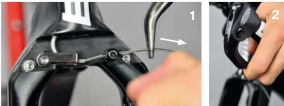
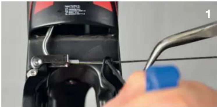
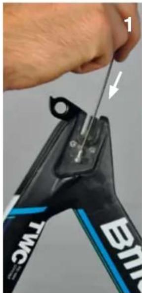
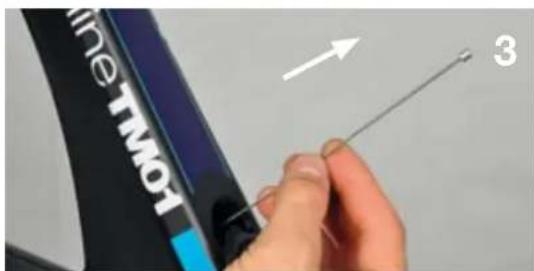
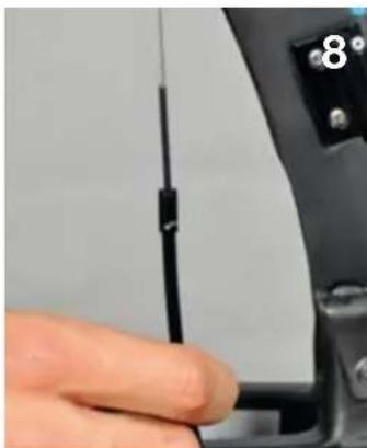
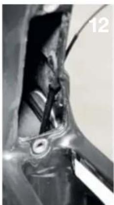
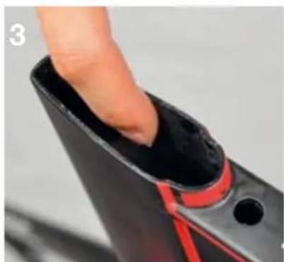
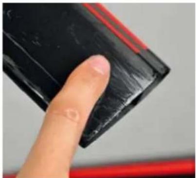
Brake cable routing (front)
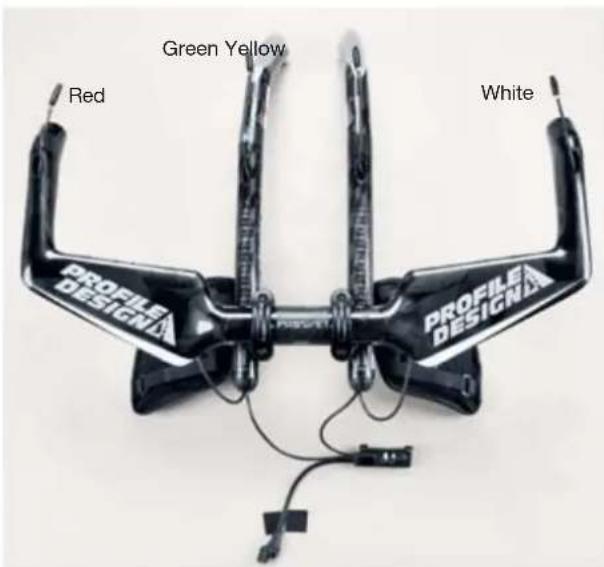
- Run the brake cable in the bars (1), and then inside the fork (2), either on left or right hand side depending on how you run your brakes.
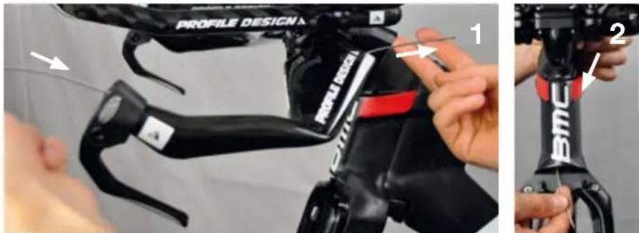
- Use the cable as guide to slide in the housing (3). Pull on the cable until the housing sits well in the brake lever (4).
- Mark where the housing exits the fork (5), then take it out of the fork and cut it shorter 15mm from the mark (6). Reinstall the housing into the fork, using the cable as guide.
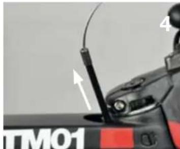
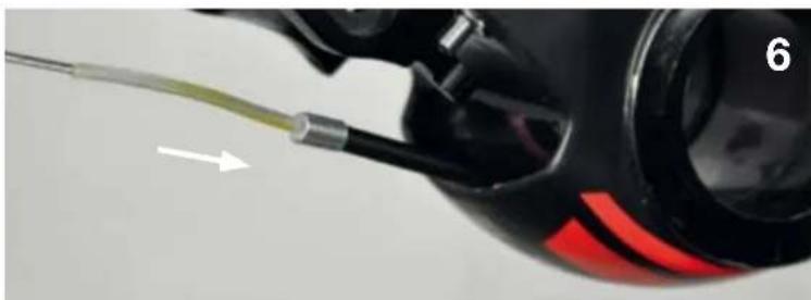
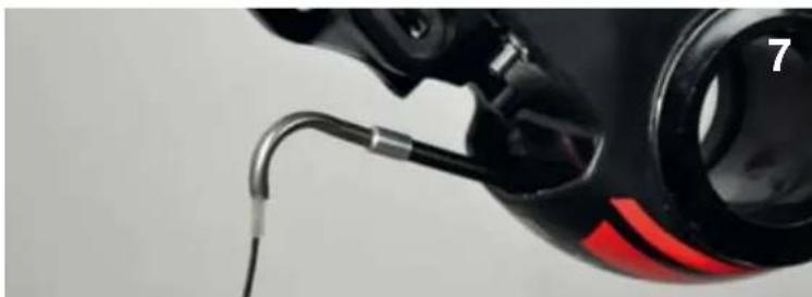
Installing the pipe on front brake
- Always run the housing of the pipe onto the cable first (7), then run the cable into the metallic pipe (8). Pull the cable until the housing sits well inside the pipe (9).
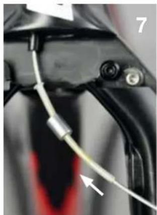
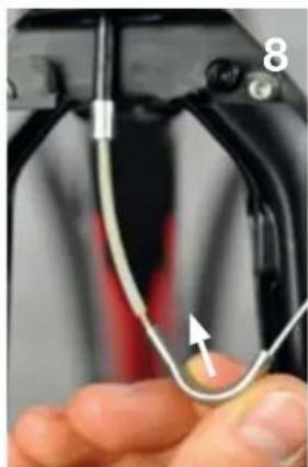
- Install the pipe holder while running the brake cable through the brake arm.
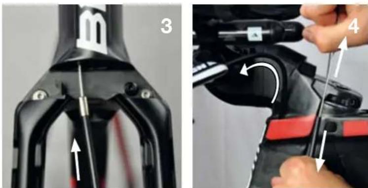
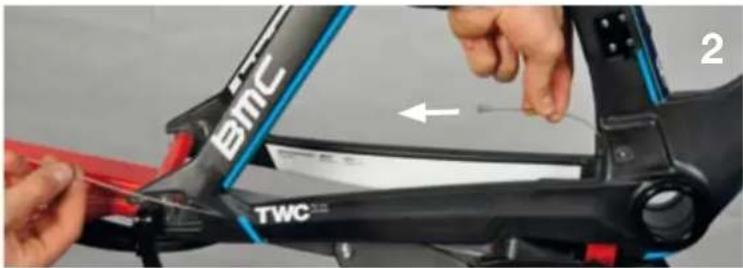
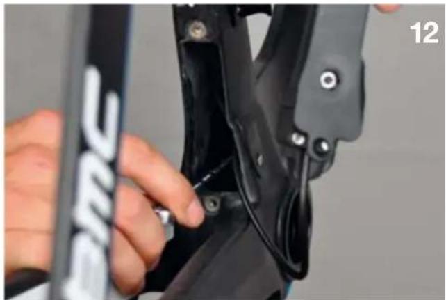
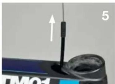
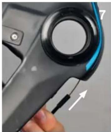
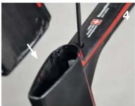
Brake cable routing (rear)
- Run the rear brake cable inside the bars (1) and then the frame, entering the top tube with the cut end of the cable (2).
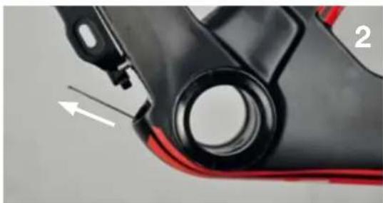
- Use the cable as guide to slide in the cable housing (3).
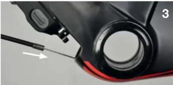
- Remove the cable and cut the housing at the exit of the frame, below the BB (5).
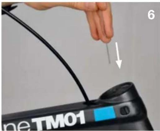
- Installing the pipe: Always run the housing of the pipe onto the cable first (6), then run the cable into the metallic pipe (7). Pull the cable until the housing sits well inside the pipe.
- Install the pipe holder while running the brake cable through the brake arm (8).
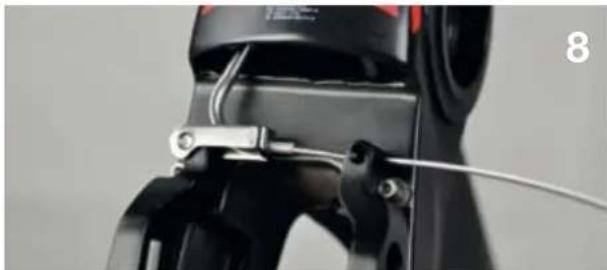
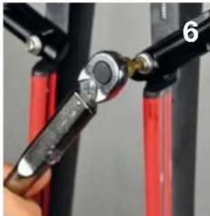
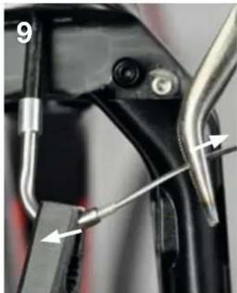
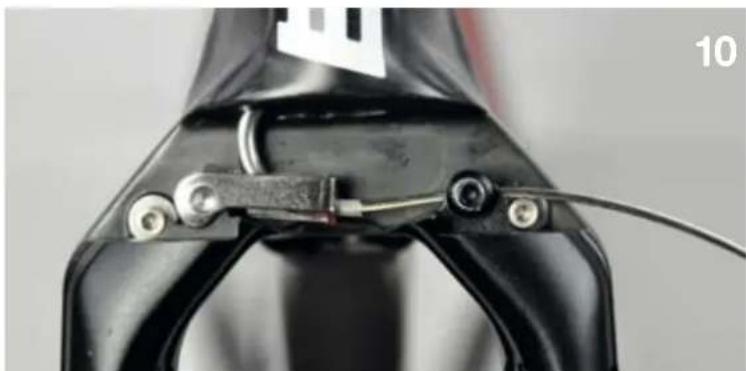
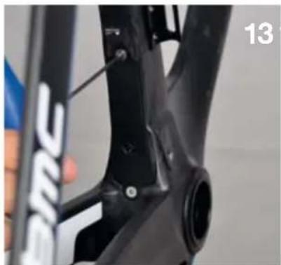
Cable tension (front brake)
It is important to understand that cable tension is independent from the position of the brakes. It means you cannot adjust the brake pad reach by adjusting cable tension. The reach of the pads is adjusted directly on the pads with spacers.
- When you clamp the cable (2.5mm Allen), maintain the brake arms against the stoppers, and apply tension to the brake cable (1). Once the cable is tight, check the function of the brake lever (2). There should not be play in the lever and the brake arms should come back all the way to the stoppers. Repeat operation if needed.
- Cut the cable against the brake arm by removing the brake stopper (3).
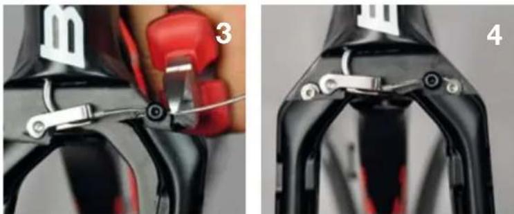
- Bolt on the brake cover (only the front brake has a cover).
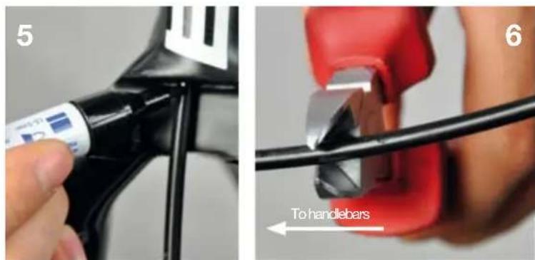
Cable tension (rear brake)
- Maintain the brake arms against the stoppers, apply tension on the cable and clamp the cable (1). Once the cable is tight, check the function of the brake lever. There should not be play in the lever and the brake arms should come back all the way to the stoppers. Repeat operation if needed.
- Cut the cable 40mm away from the brake arm (1), then clip the cable back into the down tube (3).
Brake pads setting
To mount various rim dimensions, and also to compensate pad wear, the reach of the brake pads needs to be adjusted with spacers. Please refer to your wheels manufacturers instructions regarding which brake pad compound you should use.
Exemple: Pads fully in and fully out:
| Description Part N° | ||
| Front pad set 210536 | ||
| Rear pad set 210537 | ||
| 1 Brake pad | ||
| 2 Socket | ||
| 3 0.5mm spacer | ||
| 4 1.2mm spacer | ||
| 5 2mm spacer | ||
| 6 Brake pad bolt |
3 different spacers are delivered with the bike: 0.5mm (x2), 1.2mm, 2mm
Recommended spacer installation (with new brake pads):
| Rim width Spacers (per side) | ||
| Zipp 808 26 -1.5 | (pads grinded) | |
| 23 | 0 | |
| 22 0.5 | ||
| 21 1 | = 0.5 + 0.5 | |
| Easton / Shimano | 20.6 1.2 | |
| 19.6 1.7 | = 1.2 + 0.5 | |
| Mavic (standard alloy wheels) | 19 | 2 |
| 18.6 2.2 | = 1.5 + 0.5 + 0.5 | |
| 182.5 | = 2 + 0.5 | |
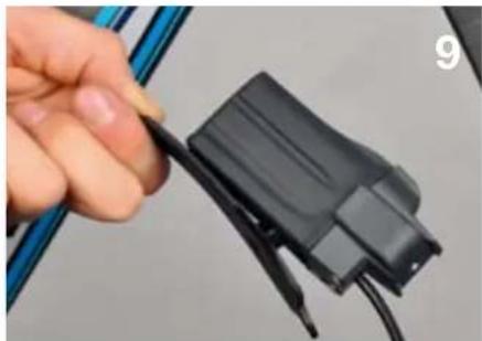
Di2 shifting
The timemachin frameset is 100% compatible and retrocompatible with mechanical (Shimano, Sram and Campagnolo) and electronic (Shimano) groupsets.
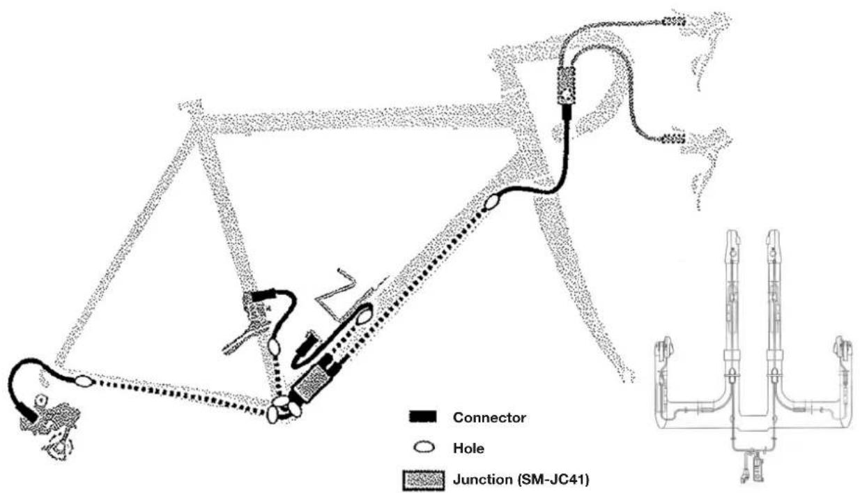
The following instructions will help you to install the Di2 cables inside the timemachine frame, it will not guarantee a proper function of your groupset.
Therefore, before installation, we recommend you to read the instructions provided by Shimano.
| Description Part N° | ||
| 1 Battery cover 210543 | ||
| 2 Cable stop cover 210996 | ||
Cable routing
- Use a shifting cable as guide to insert the rear derailleur wire (3). Enter from the drop out (1) and exit on top of the BB (2).
- Use a shifting cable as guide (5) to insert the wire from the junction to the handlebars. Enter over the BB towards the head tube (6).
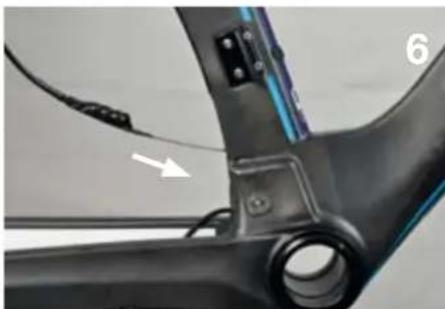
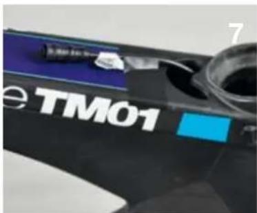
- Insert the front derailleur wire.
- Bolt the battery support onto the battery cover (8) and install the battery (9) (battery charged).
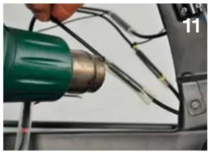
- Connect all wires to the junctions (10), use the heat gun to seal the connections (11).
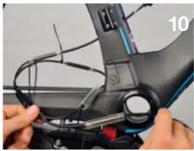
- Push the junction and the wires inside the downtube of the frame, using the 9mm wrench (12).
- Bolt the battery cover onto the frame (13), install rubber grommet (14).
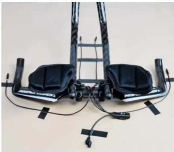
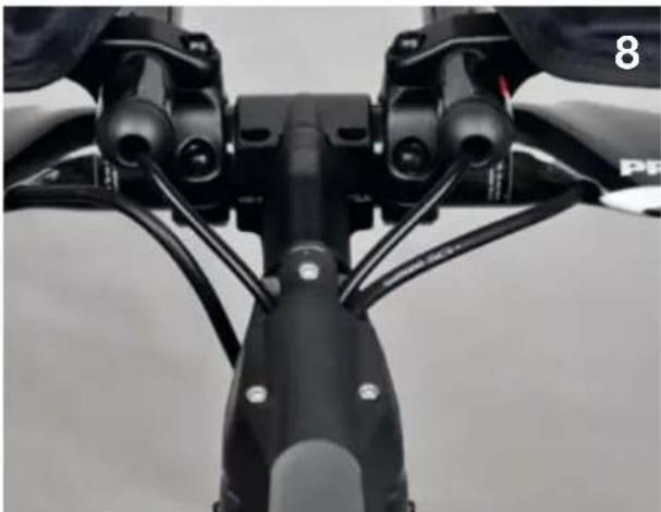
Handlebars specifics
It is possible to cleanly integrate the Di2 wires into the handlebars delivered with the timemachine complete bikes. Refer to Shimano documents to position the cables.
Mechanical shifting
The timemachine frameset is 100% compatible and retrocompatible with both mechanical (Shimano, Sram and Campagnolo) and electronic (Shimano) groupsets. The following instructions will help you to install the shifting cables inside the timemachine frame, it will not guarantee a proper function of your groupset.
Therefore, before installation, we recommend you to read the instructions provided by the manufacturer of your groupset.
Cable routing
Please note:
The cable routing uses full housing from handlebars to rear deraillur, and full housing from shifting lever to front deraillur cable stopper.
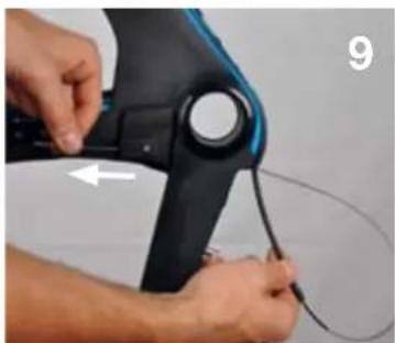
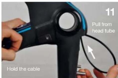
- Place the frame vertical, drop outs on top. Enter at the drop outs (1), run the cable over the BB (2) and push towards head tube (3). Use a cable to guide the rear deraillour housing (4 and 5).
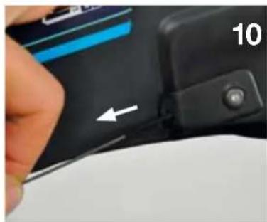
- Use a shifting cable (6) to guide the front derailleur cable housing (7). Exit below the BB at the down tube window. Insert a nosed end cap on the extremity of the cable housing (8).
- Let the cable do a loop (9) and run the cable through the cable stopper (10). Then pull the housing (11) until the nosed end cap is fully in the cable stopper (12).
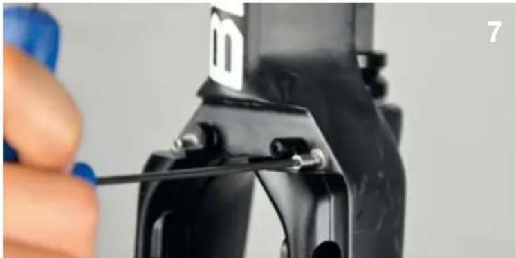
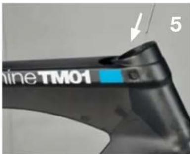
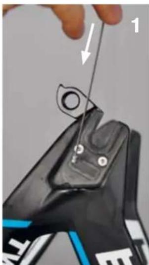
Hingefork and headset Parts overview
| Description Part N° | ||
| 1 Hingefork 210510 (S Red) | 210511 (M Red) 210512 (L Red) 210799 (S Blue) 210800 (M Blue) 210801 (L Blue) | |
| 2 Steer tube 210527 (S) | 210528 (M) 210529 (L) | |
| 3 Bearingsings 210994 | ||
| 4 Lower crown race | 210526 | |
| 5 Upper crown race | 210526 | |
| 6 Slotted sleeve | 210526 | |
| 7 Top cap | 210526 | |
| 8 Headset bolt 210526 | ||
| 9 Stem cover | 210524 | |
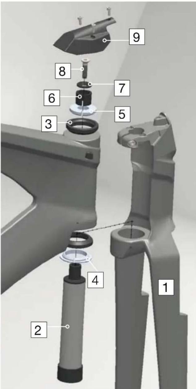
Assembly procedure
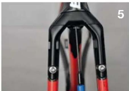
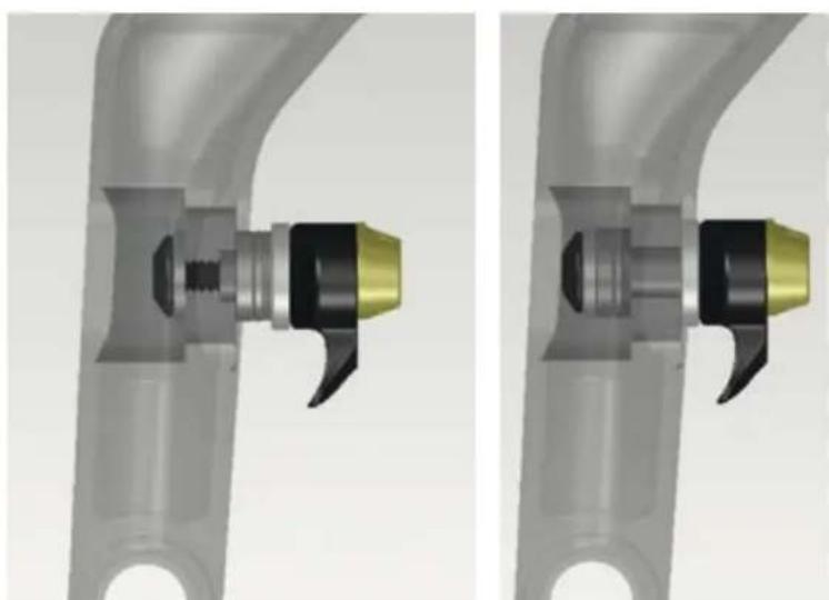
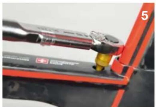
- Apply grease on the bearing seats (1) and all metal parts (2). Install bearings and crown races (3).
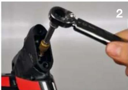
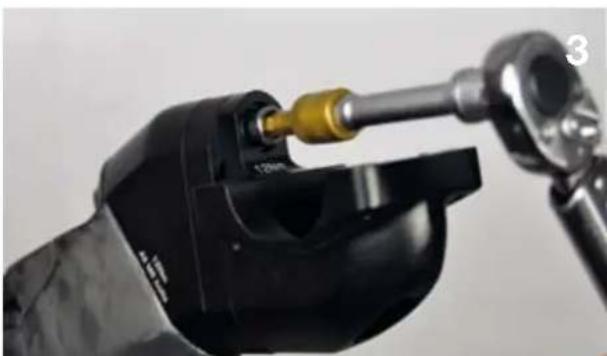
- Slide the fork on top of the crown race (4) and insert the steer tube from the bottom up (5). Tighten the steer tube to 8 Nm with 8mm Allen ratchet wrench (6).
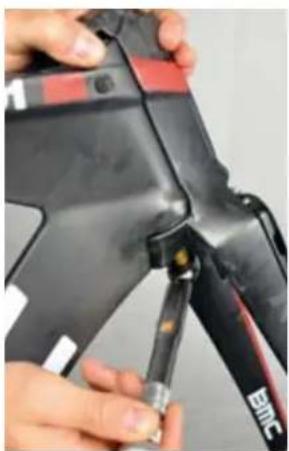
- Push in slotted sleeve (7), install top cap and bolt. Tighten lightly to preload the bearings (8).
- Lightly tighten the fork clamp (9) (4mm Allen, max torque 2.0 Nm).
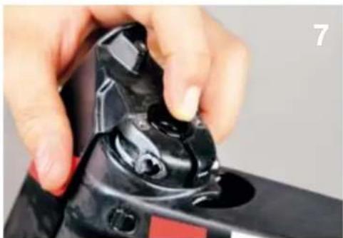
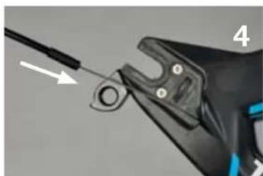
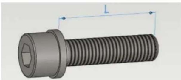
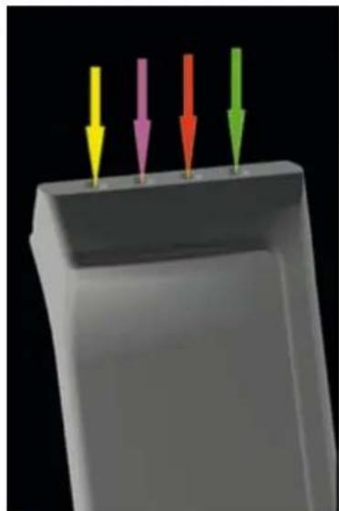
P2p stem system
The timemachine stem is designed to achieve a high level of adjustability with a simple part kit. It is a modular system that uses elements which can be combined in different ways to obtain different height and reach of your handlebars. To choose which elements to install in order to reach a given position, please go to the first chapter "Positioning".
Parts overview
| Description Part N° | ||
| 1 Faceplate w/bolts 210520 | ||
| 2 Stem body 210520 | ||
| 10° angled spacer w/bolts 210522 | ||
| 3 30° angled spacer w/bolts 210523 | ||
| 4 10mm spacer 210521 | ||
| 5 20mm spacer 210521 | ||
| 6 Length spacer bolts 210521 | ||
| 7 Stem cover 210524 | ||
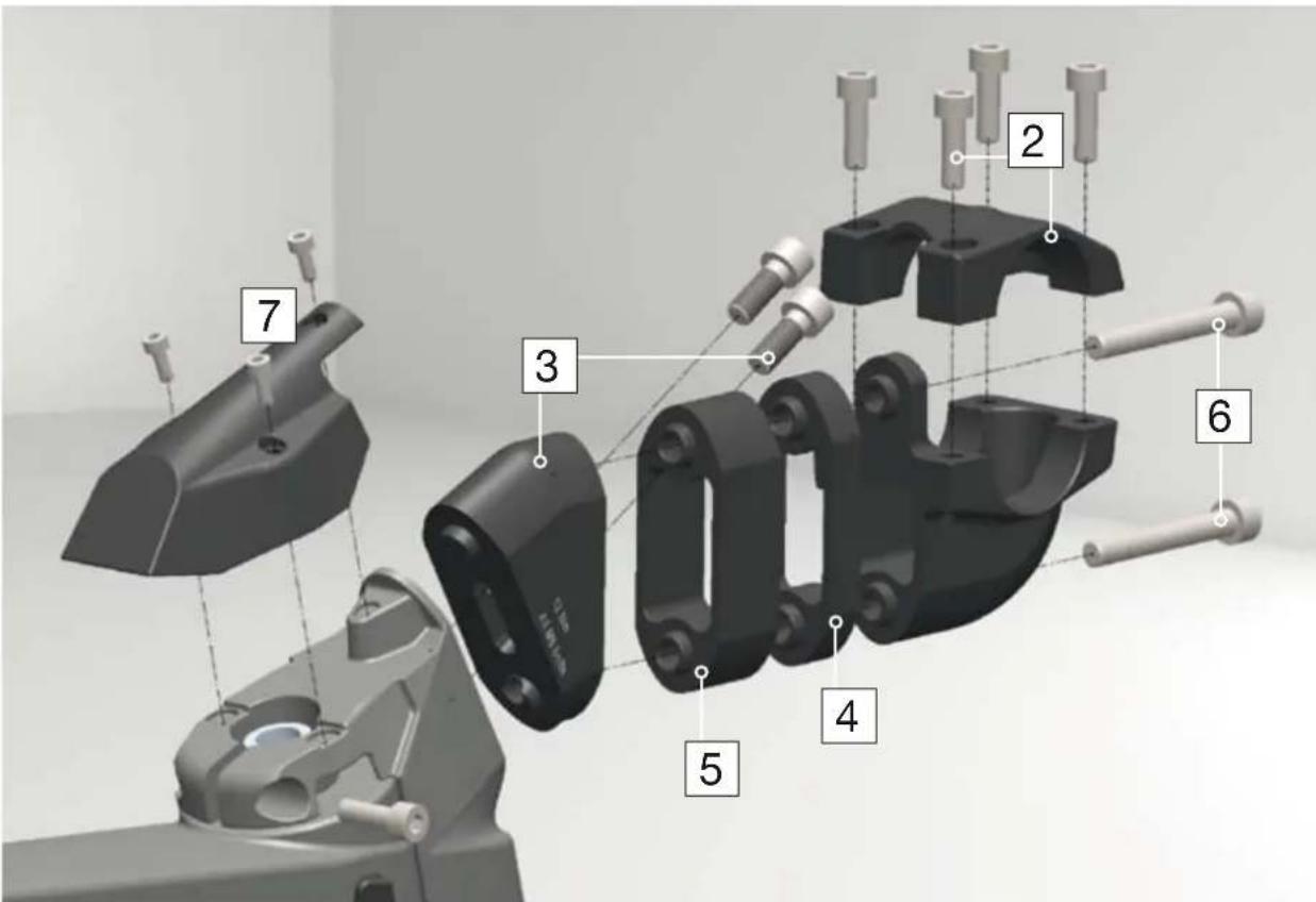
- Each stem element can be flipped 180^ to shift position.
- It is possible to use 1, 2 or none of the length spacers.
- There are 2 angles provided with the stem, it is not possible to mount the stem without angled spacers.
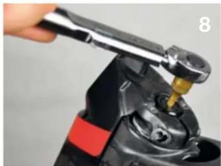
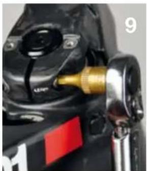
Assembly procedure
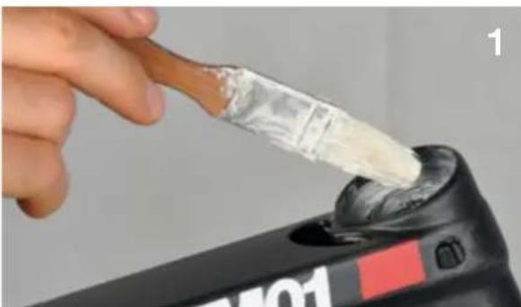
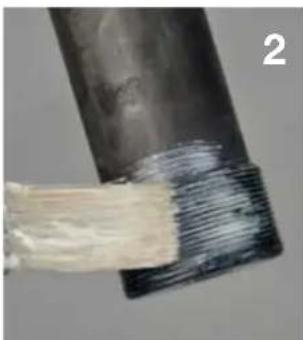
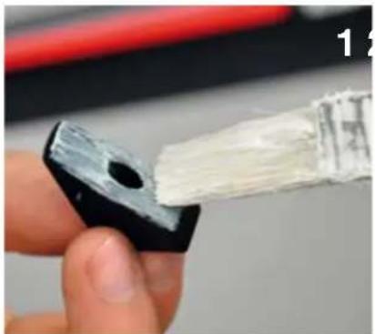
- Apply friction paste on the contact surface of the fork (1).
Install first the angled spacer, using 16mm M6 bolts. Torque 12 Nm (2).
- Install stem body with the desired length spacing (3).
Important: Each length spacing has a corresponding specific bolt length. Incorrect bolt length may result in damaged stem and fork!
| Spacer combination Length L | |
| No spacers 16mm | |
| 10mm spacer 26mm | |
| 20mm spacer 36mm | |
| 10 + 20 spacers 46mm |
- Apply friction paste between stem and handlebars. Install handlebars and faceplate. The frontal bolts of the face plate should be tightened until the face plate touches the stem body.
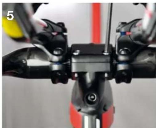
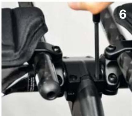
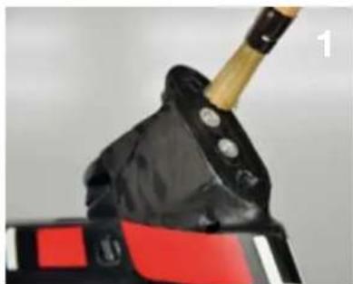
- Once the cables are installed and the handlebar setup is correct, bolt on the stem cover.
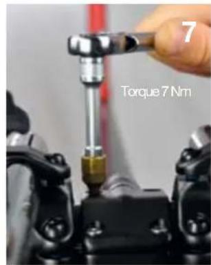
P2p seatpost
Seat clamp
| Description Part N° | ||
| Seat post clamp kit 210531 | ||
| 1 Bolt | ||
| 2 Washer | ||
| 3 Nut | ||
| 4 Upper wedge | ||
| 5 Lower wedge |
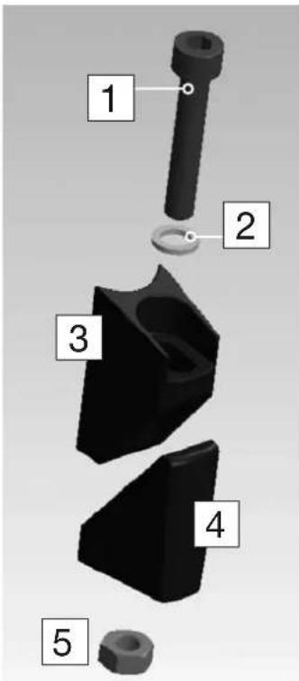
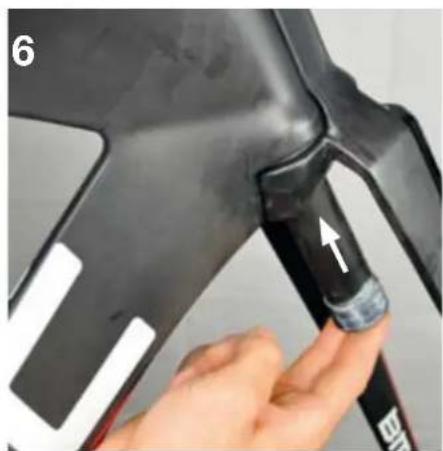
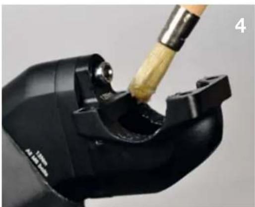
- Apply grease in between the 2 wedges, friction paste in the seat tube and on the seat post.
- Insert the seat clamp unit into the frame and hold it in place with the 4mm allen key. Insert the post and tighten the bolt. Max torque 7.5 Nm.
Service instructions
The BMC timemachine is a high-tech, performance oriented product. We ask you to specially take care of your bike if you want it to deliver the maximum of it's performance over the years.
If you notice parts that are worn out or damaged, do not hesitate to replace the part and or contact your BMC dealer.
Washing your bike
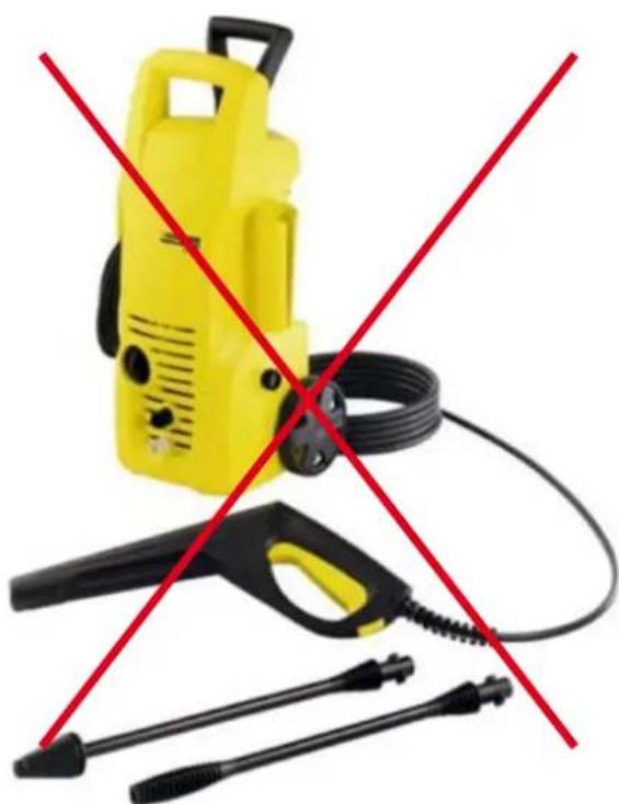
You should never use high pressure washing device to clean your timemachine.
The integrated components of the frameset were designed to be integrated and aerodynamically efficient, they were not designed to be water-tight at high pressure.
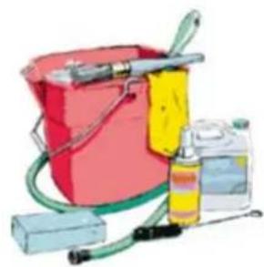
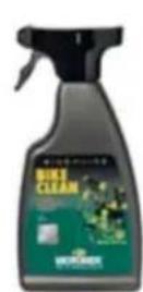

We recommend to use a brush and detergent such as Motorex BIKE CLEAN, rinsed with water.
After washing
- If there is water trapped in your frame, it will drain automatically from below the BB.
- If you feel unusual friction in the front brake assembly, take off the front brake cover and make sure nothing is hindering the movement of the brake.
- If the steering does not rotate freely after long term storage of the bike, your headset bearings need to be replaced.
Refer to page 32 for instructions.
- If your seatpost makes unusual noise after washing or riding in wet weather, you need to take the seatpost apart and reapply carbon grease between frame and seatpost. Refer to page 33.
Troubleshooting
Noise from the saddle:
o Apply friction paste between the seatpost hardware components.
Noise from the seatpost:
o Apply friction paste between the seatpost shaft and the frame.
Seatpost slipping down:
o Apply friction paste between the seatpost shaft and the frame.
o Control the torque at the seat clamp: Max torque 7.5 Nm.
Play in the headset:
o Remove stem cover, unlock stem bolt and tighten lightly the headset bolt. Refer to page 29.
Friction in the headset
o Make sure nothing is stuck in between frame and fork.
o Take apart the headset and replace the bearings. Refer to page 32.
Play in the handlebars:
o Do not ride with play in the stem system.
o Control the torque settings of the bolts attaching the stem to the fork. Refer to page 32.
o Control that none of the stem bolts is damaged.
Rear wheel moving while riding:
o Control that the rear wheel adjusters are positioned tight against the hub. There must be constant pressure from the adjusters when you secure the rear wheel in place with the quick release lever.
Play in the brake levers:
o Control brake cable tension: Proceed again to the steps described page 21-22.
The brake lever has too much reach:
o Control if there is play in the brake lever. If not, the brake pads needs to be spaced towards the rim. Add spacers between the pads and the brake arms. Refer to page 22.
I am switching from my training wheels to my race wheels, which are wider:
o Some carbon rims are much wider than standard alloy wheels. It is often needed to remove the spacers between brake pads and brake arms. It can also be needed to use thinner brake pads to fit the widest rims.
o We recommend you to keep a pair of racing brake pads (matching the pair of race wheels) and a pair of training pads (matching the training wheels).
timemachine
OWNERS MANUAL
Owners Manual - german
Inhalt
Owners Manual
Einleitung 3
SSB (saddle seat back)
Farbcode
Owners Manual - french
CONTENTS
Owners Manual
Introduction 3

SSB (saddle seat back)

Code couleur
Outillage recommende
Owners Manual - Italian
Summario
Owners Manual
Introduzione 3
Owners Manual - dutch
INHOUD
Owners Manual
Inleiding 3
Once you know your SSnew and RSnew: