Teammachine SLR01 - Bike BMC - Free user manual and instructions
Find the device manual for free Teammachine SLR01 BMC in PDF.

| Product type | Road bike |
| Brand | BMC |
| Model | Teammachine SLR01 |
| Frame material | Carbon |
| Frame weight (approximate) | ~800 g (not officially specified) |
| Power supply (Di2) | Internal Shimano Di2 battery housed in the seatpost |
| Main functions | Pedaling, mechanical or electronic Di2 shifting, braking |
| Compatible drivetrain type | Mechanical (cables) or electronic Di2 |
| Maintenance and cleaning | Clean the frame with a soft cloth and soapy water; lubricate the chain regularly |
| Safety | Check screw tightening (max torque: seatpost 5 Nm, saddle clamp 7 Nm) |
| Spare parts and repairability | Di2 battery, cables, housing, headset bearings, brake pads |
| General information | User manual available for free in PDF on notice-facile.com |
Frequently Asked Questions - Teammachine SLR01 BMC
User questions about Teammachine SLR01 BMC
0 question about this device. Answer the ones you know or ask your own.
Ask a new question about this device
Download the instructions for your Bike in PDF format for free! Find your manual Teammachine SLR01 - BMC and take your electronic device back in hand. On this page are published all the documents necessary for the use of your device. Teammachine SLR01 by BMC.
USER MANUAL Teammachine SLR01 BMC
ASSEMBLY INSTRUCTIONS
MONTAGEANLEITUNG
INSTRUCTIONS DE MONTAGE

natural_image
Abstract geometric shape with white lines on gray background, no text or symbols presentContent
ASSEMBLY INSTRUCTIONS
Introduction 4
Gear cable routing for mechanical shifting 6
Di2 gear cable routing 7
Rear brake cable 11
Headset and Fork Installation 13
Seat clamp & seat post Installation 14
Notes 15

natural_image
Abstract geometric shape with white lines on gray background, no text or symbols presentIntroduction
The new BMC teammachine SLR01 frameset and components are designed as a system to provide a very high level of riding performance.
Integration being a key part of the system's performance, it is necessary to understand that most components of the frameset have been designed specifically for the new teammate SLR01 and their function may slightly differ from your traditional road bike "off the shelf" components.
The new BMC teammachine SLR01 uses all the latest and most high-end technologies that can be found in bicycle manufacturing, including sharp edged and thin-walled carbon fibre composite construction, which should be treated with delicacy from the end user to prevent permanent and sometimes invisible damage.
For the reasons mentioned above, we ask you to carefully follow the instructions provided in this manual.
Incorrect mechanical operation on your bicycle could lead to serious damage, which could cause you to fall and lead to injury or death.
If you do not have the appropriate tools or experience to execute the following instructions, or if you need further information, please contact your official BMC dealer for service of your bicycle.

natural_image
Abstract geometric shape with white lines on gray background, no text or symbols presentGear cable routing for mechanical shifting
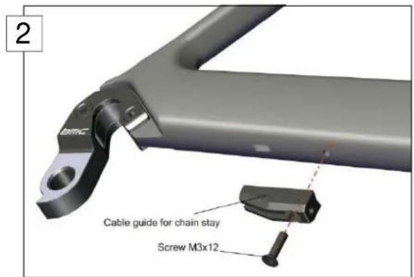
- Prepare the frame for mechanical gear routing with the DT stopper (1) and the cable guide below the right chain stays (2).
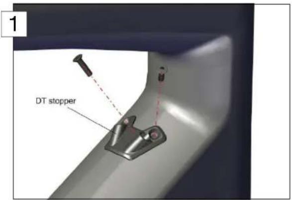
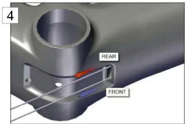
- Insert the rear derailleur cable (later RD cable) through the DT (3) stopper and exit it through the long hole near the bottom bracket (4). Repeat the operation for the front derailleur cable (later FD cable).
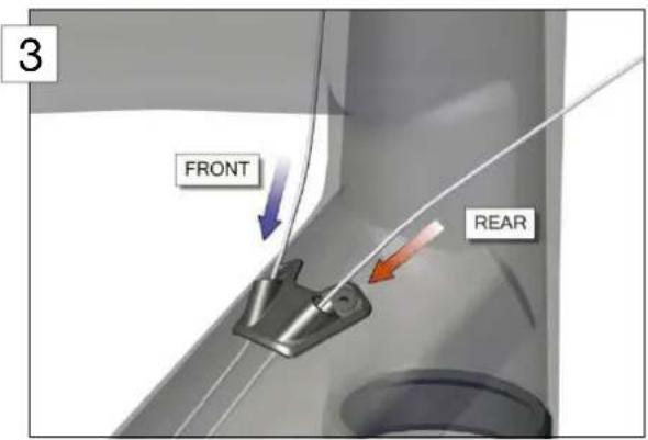
Note: For non-crossed shifting housings at cockpit (REAR cable entering right and FRONT cable entering left, as shown on the pictures above), the two cables need to run parallel through the DT. For crossed shifting housings at the cockpit (REAR cable entering left and FRONT cable entering right), the shifting cables need to be crossed again through the DT.
Important: please note that twisted cables are prohibited for both configurations (crossed, non-crossed). This would lead to inaccurate and bad shifting when changing gears.
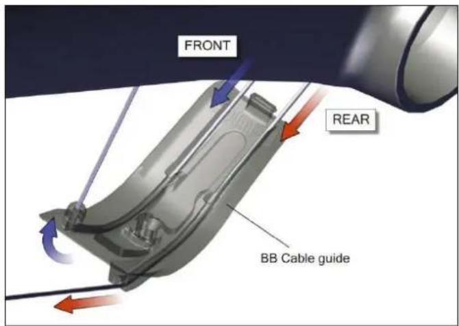
- Run the cables through the BB cable guide and take care on the respective grooves for RD cable and FD cable.
-
Insert the FD cable through the hole running behind the bottom bracket.
-
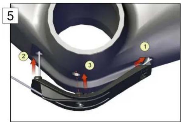
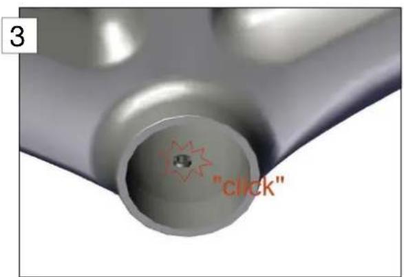
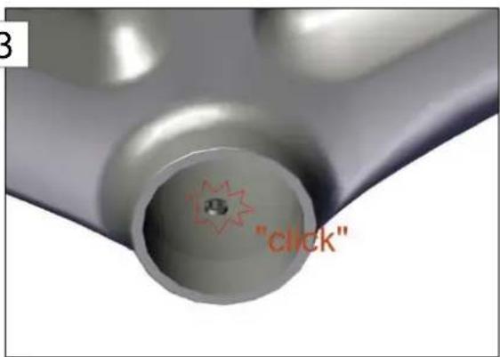
Place the cable guide inside the specific recess below the bottom bracket by clipping it front side first ①, then by pushing straight on the FD cable ② (5).
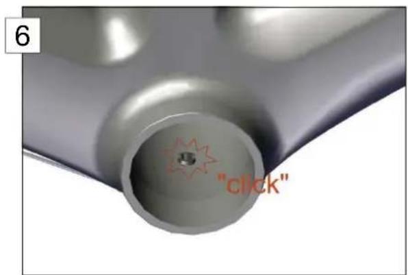
Complete by pushing in the middle of the cable guide straight on the clip ③ until you hear the "click" sound (6).
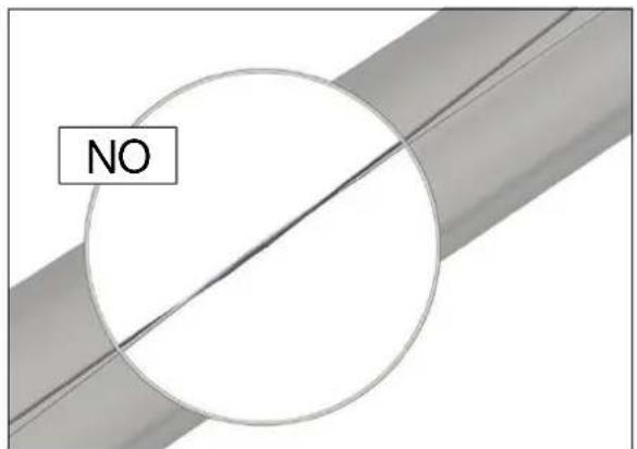
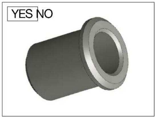
- Run the RD cable through the cable guide below the chain stays, enter it at the bottom side of the chain stay and exit it through the hole above the drop out.
Then, put on the DO stopper and push it inside the hole.

Note: the DO stopper is cylindrical. There is no flat surface on it, and in opposition with the rear brake cable stopper (described in point 5. of section "Rear brake cable")
natural_image
3D rendered mechanical part with a hollow cylindrical body and flange, labeled 'YES NO' in the top-left corner (no other text or symbols)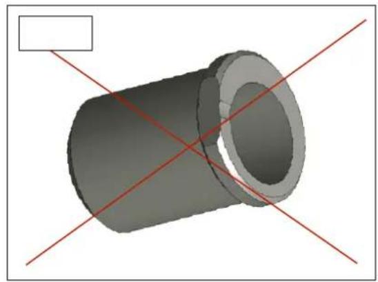
natural_image
3D rendering of a cylindrical mechanical part with red diagonal lines intersecting, no text or symbols presentDi2 gear cable routing
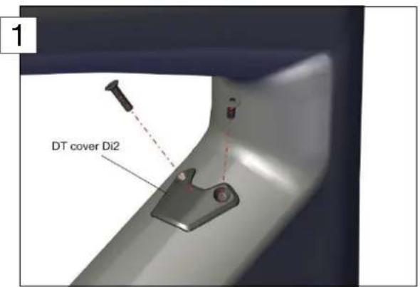
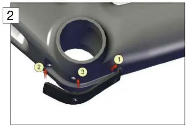
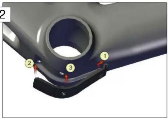
- Prepare the frame for Di2 gear cable routing by installing the DT cover (1) and the BB cover as shown on the picture (2) below. Please make sure that the BB cover is well clipped inside the frame (3).
When needed, please look at the instructions described in point 5. of section "Gear cable routing for mechanical shifting".

- Use a mechanical wire gear shifting cable to guide the Di2 rear derailleur wire through the chain stay. Enter the frame at the drop out and exit at the bottom bracket.
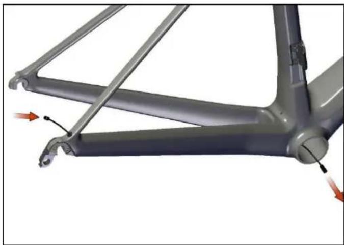
natural_image
Mechanical assembly diagram showing a frame with attached components and directional arrows indicating motion (no text or symbols)- Use a mechanical wire gear shifting cable to guide the Di2 main wire through the down tube. Enter at the hole on the head tube and exit at the bottom bracket.
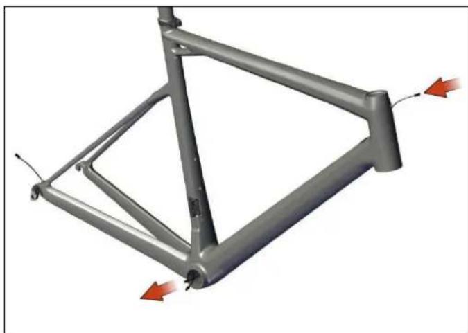
natural_image
3D model of a metal frame structure with red directional arrows indicating force or movement (no text or symbols)- Insert the Di2 front derailleur wire from the hole located near the front derailleur and exit at the bottom bracket.
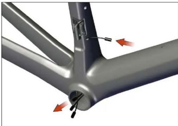
natural_image
Mechanical assembly diagram showing a metal frame with internal components and red directional arrows indicating motion (no text or symbols)- Guide the wire from the top of the seat tube towards the bottom bracket and exit there.
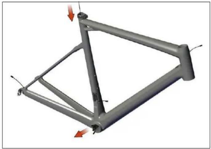
natural_image
3D mechanical frame structure with red directional arrows indicating force or movement (no text or symbols)-
Mount the battery inside the seat post:
-
snap the threaded Battery adapter over the battery,
- screw in the adapter until the Hex touches the foam,
- connect the battery to the Di2 cable.
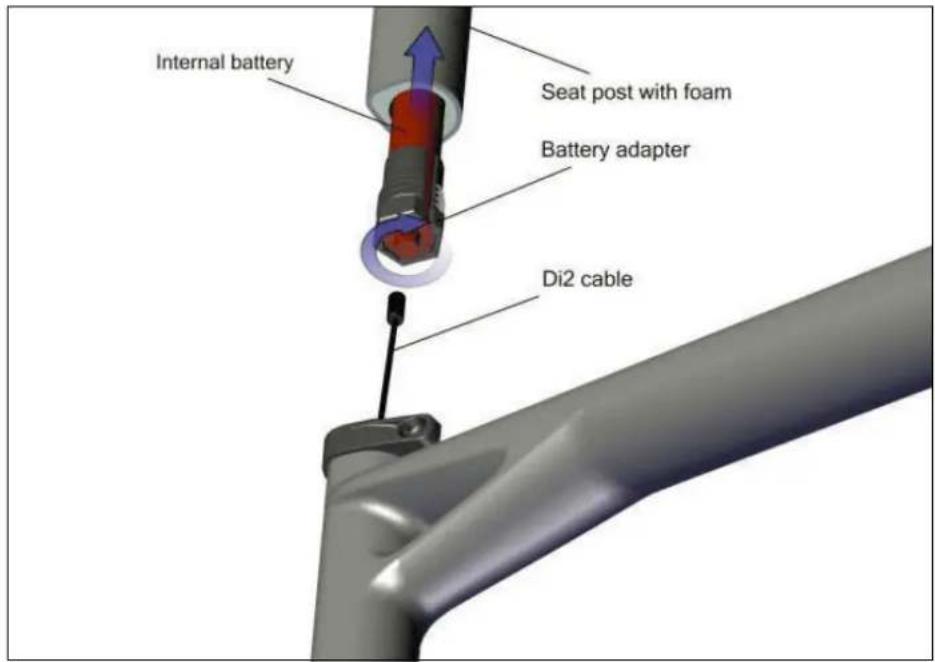
Note: Cutting the seatpost to maximum length of 80mm (measured from BOTTOM of seatpost) can be done without affecting the structure of the seatpost.
WARNING: If the seatpost is cut, this is at the owner's risk and BMC are not liable for any possible related issues. Once a seatpost is cut, it also voids the warranty of that post.
- Connect all Di2 wires coming out of the bottom bracket to the junction, please refer to Shimano installation instructions.
-
Push the wires and the junction back into the bottom bracket and the seat tube.
-
Install the Di2 plug at the drop out.
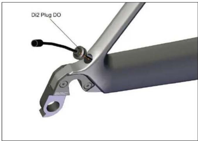
- Install the Di2 grommets. Please refer to Shimano instructions.
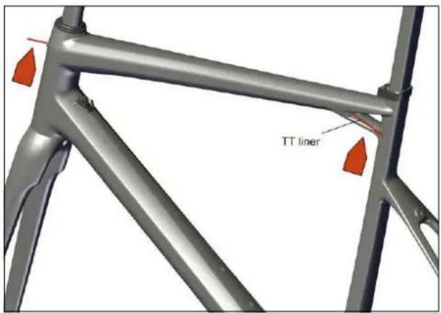
Rear brake cable
- Make sure that the frame is ready for the rear brake cable routing by checking the liner's presence through the top tube.
- Please refer to the following chart in order to pre-define the length of the rear brake cable housing. This length (in mm) is measured from a point on the handlebar 60mm away from the center of the stem to the cable entrance at the head tube:
| Spacers Stem length** (mm) | |||||||
| height* 80 90 | 100 110 120 | 130 140 | |||||
| <30mm 180 190 | 195 200 210 | 215 220 | |||||
| >30mm 185 195 | 200 205 215 | 220 225 | |||||
* the spacers height includes the conical top cap below the spacers (low=8mm or high=15mm)
** the reference stem has an angle of -6°
Note: this table should be used as a guide only.
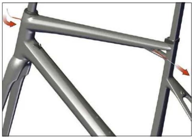
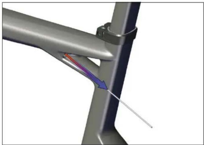
- Insert the cable through the liner.
natural_image
Metal frame structure with red directional arrows indicating force or movement (no text or symbols)- Remove the liner by pulling backwards.
natural_image
3D diagram of a mechanical joint or pipe with color-coded flow arrows indicating direction (no text or symbols)Note: the liner makes your life easier in case of cable replacement. We suggest you to keep it in a nice storage place for the time you will need it again.
- Insert the rear brake stopper out of the cable. Please make sure that the flat surface is directed downward when installing the stopper inside the frame.
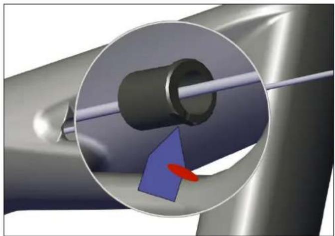
natural_image
Close-up of a mechanical component with a blue arrow and red oval highlighting a specific area (no text or symbols)Note: the rear brake stopper has a flat surface on the retaining wall, differentiating it with the DO stopper (described in point 6. of section "Cable routing for mechanical gear shifting").
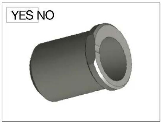
natural_image
3D rendered mechanical part with a cylindrical body and flange, labeled 'YES NO' in the top-left corner (no other text or symbols)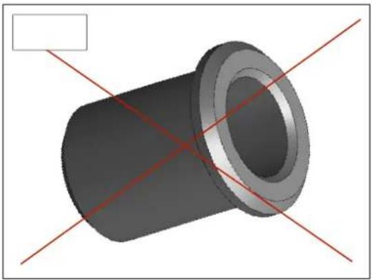
natural_image
3D rendering of a mechanical component with red alignment lines (no text or symbols)Headset and Fork Installation
- Apply grease on the bearings (N°3 and 4) and on the bearing seats of the frame. Place the bearings in the frame.
- Apply grease on the shaft and on the crown of the fork (N°5), and then slide it through the bearings and the head tube.
- Slide the compression ring (N°2) over the fork shaft.
- Slide the top cap (N°1) over the compression ring and then setup your stem.
Note: 2 different heights of top caps are delivered with the frame (low=8mm, high=15mm). Feel free to use the one which matches your position the best.
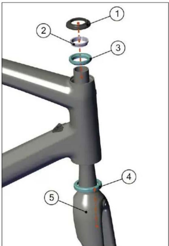
Note: the fork crown is designed so that the lower bearing can seat directly on it. There is no need to add a metal ring.
Seat clamp & seat post Installation
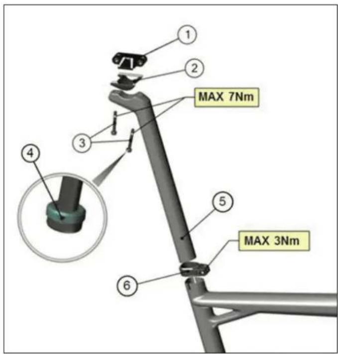
- Install the saddle clamping hardware, by applying carbon friction paste at the lower clamp interface (between 2 and 5). Bolts (3) are then assembled with upper seat clamp (1) through the seat post (5). Take care that the spherical washers (4) are together with the bolts when assembling, and don't exceed the maximum torque of 7Nm when tightening.
- Apply carbon friction paste on the lower part of the seat post (5) as well as on the inside of the seat tube.
- Ensure that the seat clamp (6) is mounted on the frame.
- Insert the seat post into the seat tube.
- Tighten the seat post clamp bolt to 5Nm max.
Notes
Notes

natural_image
Abstract geometric shape with white lines on gray background, no text or symbols presentInhalt
MONTAGEANLEITUNG
Einleitung 22
natural_image
Abstract geometric shape with white lines on gray background, no text or symbols presentEinleitung
The new BMC teammachine SLR01 frameset and components are designed as a system to provide a very high level of riding performance.
Integration being a key part of the system's performance, it is necessary to understand that most components of the frameset have been designed specifically for the new teammachine SLR01 and their function may slightly differ from your traditional road bike «off the shelf» components.
The new BMC teammachine SLR01 uses all the latest and most high-end technologies that can be found in bicycle manufacturing, including sharp edged and thin-walled carbon fibre composite construction, which should be treated with delicacy from the end user to prevent permanent and sometimes invisible damage.
For the reasons mentioned above, we ask you to carefully follow the instructions provided in this manual.
Incorrect mechanical operation on your bicycle could lead to serious damage, which could cause you to fall and lead to injury or death.
If you do not have the appropriate tools or experience to execute the following instructions, or if you need further information, please contact your official BMC dealer for service of your bicycle.

natural_image
Abstract geometric shape with white lines on gray background, no text or symbols present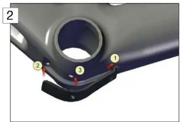
natural_image
Mechanical assembly diagram showing a frame with attached components and red directional arrows indicating motion (no text or symbols)natural_image
Metal frame structure with red directional arrows indicating force or movement (no text or symbols)natural_image
Mechanical assembly diagram showing a bracket with red arrows indicating force or motion direction (no text or symbols present)natural_image
3D mechanical frame structure with red directional arrows indicating force or movement (no text or symbols)natural_image
Metal frame structure with red directional arrows indicating force or movement (no text or symbols)natural_image
3D rendering of a mechanical joint or bracket with a colored arrow indicating direction (no text or symbols present)natural_image
Close-up of a mechanical component with a magnified inset showing a blue arrow and red oval (no text or symbols)natural_image
3D rendering of a cylindrical mechanical part with red diagonal lines intersecting, no text or symbols presentnatural_image
Abstract geometric shape with white lines on gray background, no text or symbols presentSommaire
INSTRUCTIONS DE MONTAGE
Introduction 40
natural_image
Abstract geometric shape with white lines on gray background, no text or symbols presentIntroduction
The new BMC teammachine SLR01 frameset and components are designed as a system to provide a very high level of riding performance.
Integration being a key part of the system's performance, it is necessary to understand that most components of the frameset have been designed specifically for the new teammate SLR01 and their function may slightly differ from your traditional road bike «off the shelf» components.
The new BMC teammachine SLR01 uses all the latest and most high-end technologies that can be found in bicycle manufacturing, including sharp edged and thin-walled carbon fibre composite construction, which should be treated with delicacy from the end user to prevent permanent and sometimes invisible damage.
For the reasons mentioned above, we ask you to carefully follow the instructions provided in this manual.
Incorrect mechanical operation on your bicycle could lead to serious damage, which could cause you to fall and lead to injury or death.
If you do not have the appropriate tools or experience to execute the following instructions, or if you need further information, please contact your official BMC dealer for service of your bicycle.

natural_image
Abstract geometric shape with white lines on gray background, no text or symbols presentnatural_image
3D rendered image of a cylindrical mechanical part with flange (no text or symbols)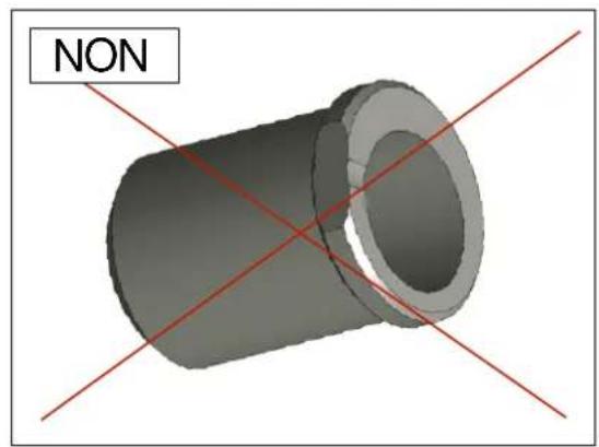
natural_image
3D rendered mechanical part with red diagonal lines and label 'NON' (no other text or symbols)2
3
natural_image
Mechanical assembly diagram showing a frame with attached joints and force arrows (no text or symbols)natural_image
Metal frame structure with red directional arrows indicating force or movement (no text or symbols)natural_image
Mechanical assembly diagram showing a three-bladed bracket with red arrows indicating motion or force directions (no text or symbols present)natural_image
3D model of a metal frame structure with red directional arrows indicating force or movement (no text or symbols)natural_image
Metal frame structure with red directional arrows indicating movement or force (no text or symbols)natural_image
3D diagram of a mechanical joint or bracket with colored arrows indicating direction (no text or symbols)natural_image
3D mechanical component with a highlighted cylindrical part and blue arrow indicating direction (no text or symbols)natural_image
3D rendered mechanical part with a cylindrical shaft and flange, labeled 'OUI NON' in the top-left corner (no other text or symbols)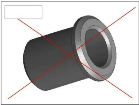
natural_image
3D rendering of a cylindrical mechanical part with red diagonal lines intersecting it, no text or symbols presentnatural_image
Abstract geometric shape with white lines on gray background, no text or symbols present