Timemachine Road TMR01 - Bike BMC - Free user manual and instructions
Find the device manual for free Timemachine Road TMR01 BMC in PDF.

| Product Type | Aerodynamic road bike |
| Brand | BMC |
| Model | Timemachine Road TMR01 |
| Frame Material | Carbon |
| Approximate Weight | ~7-8 kg (depending on configuration) |
| Compatible Drivetrain | Mechanical or Shimano Di2 |
| Brakes | BMC specific rim brakes (front and rear) |
| Headset | Integrated, model 212485 |
| Fork | Aero carbon fork (models: teamred, flame, white, stealth) |
| Seatpost | Aero carbon seatpost (models: team red, flame, shark, white) |
| Cable Routing | Internal, with cable guides and Di2 grommets |
| Battery (Di2) | Internal battery mounted in the seatpost |
| Maintenance | Use grease and carbon friction paste. Tighten screws to indicated torques (max 5Nm for seatpost, 4.5Nm for brakes, 6Nm for cables) |
| Cleaning | Clean with a soft cloth and soapy water. Avoid harsh chemicals |
| Safety | Respect tightening torques. Regularly check brakes and component attachment. Do not modify the frame |
| Spare Parts | Rear brake kit (212496), seat clamp kit (212482), bearings, grommets, etc. Available at BMC |
| Repairability | Mechanical operations should be performed by a professional. Follow the instructions in the manual |
| General Information | Bike designed for aerodynamic performance. Requires careful maintenance |
Frequently Asked Questions - Timemachine Road TMR01 BMC
User questions about Timemachine Road TMR01 BMC
0 question about this device. Answer the ones you know or ask your own.
Ask a new question about this device
Download the instructions for your Bike in PDF format for free! Find your manual Timemachine Road TMR01 - BMC and take your electronic device back in hand. On this page are published all the documents necessary for the use of your device. Timemachine Road TMR01 by BMC.
USER MANUAL Timemachine Road TMR01 BMC
ASSEMBLY INSTRUCTIONS
MONTAGEANLEITUNG
INSTRUCTIONS DE MONTAGE

Content
ASSEMBLYINSTRUCTIONS
Introduction 4
Cable routing for mechanical shifting 6
Di2 Cable routing 7
Headset & Fork installation 9
Seat clamp and seat post installation 10
Rear brake installation 11
Brake pad configuration 15
Front brake installation 16
Notes 19

Introduction
BMC timemachine TMR01 frame and components are designed as a system to provide a very high level of aerodynamics and riding performance.
Integration being a key part of the system's performance, it is necessary to understand that most components of the frameset have been designed specifically for timemachine TMR01 and their function may slightly differ from your traditional road bike "off the shelf" components.
BMC timemachine TMR01 uses all the latest and most high-end technologies that can be found in bicycle manufacturing, including sharp edged and thin-walled carbon fiber composite construction, which should be treated with delicacy from the end user to prevent permanent and sometimes invisible damage.
For the reasons mentioned above, we ask you to carefully follow the instructions provided in this manual.
Incorrect mechanical operation on your bicycle could lead to serious damage, which could cause you to fall and lead to injury or death.
If you do not have the appropriate tools or experience to execute the following instructions, or if you need further information, please contact your official BMC dealer for service of your bicycle.

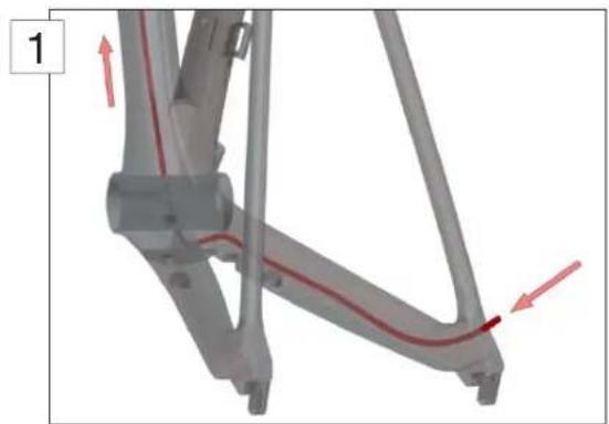
Cable routing for mechanical shifting
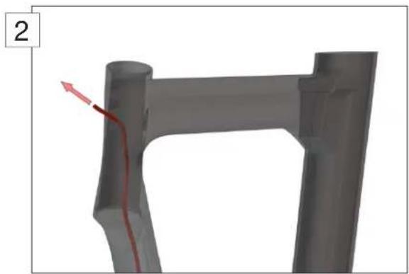
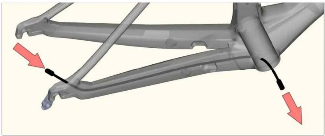
- Insert the rear derailleur cable housing from the right dropout, and then run it into the frame (1). Exit at the head tube opening on the left side (2).
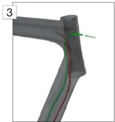
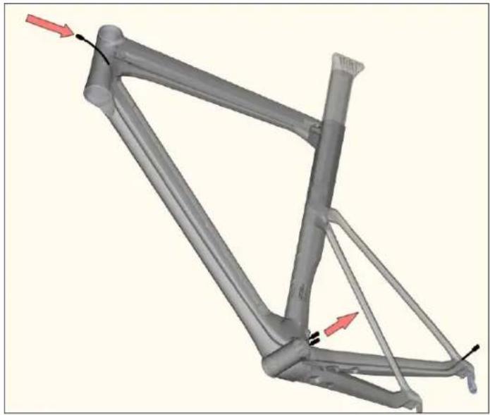
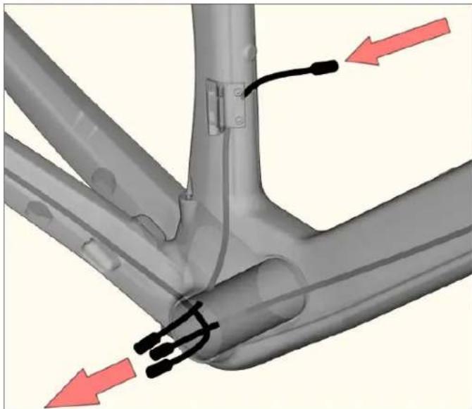
- Insert the front derailleur cable housing from the right side head tube opening (3). Run it through the down tube and exit at the bottom bracket on the left side.
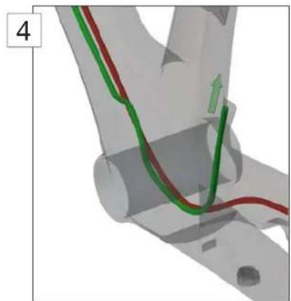
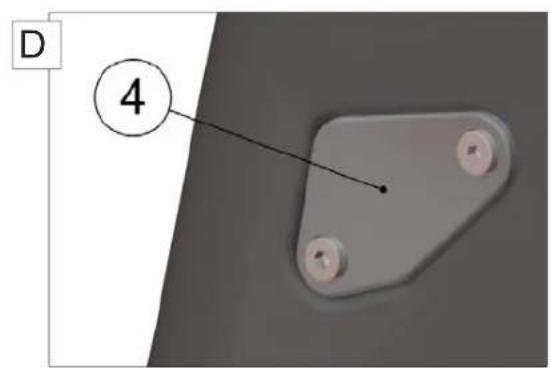
- Install the nosed end cap on the cable housing, then reenter the frame and guide the end cap into the FD cable stopper (4).
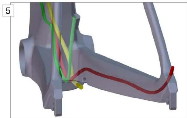
- Insert the rear brake cable housing from the head tube opening, run it through the down tube and exit at the opening behind the bottom bracket (5).
Note that the rear brake cable housing should be placed on the right side of the shifting cables.
DI2 Cable routing
Note: For all matters regarding Di2 cable routing, please refer to the official Shimano instructions. This chapter only offers guidelines in order to properly place the Shimano wires into your TMR01 frame.
- Use a shifting cable to guide the Di2 rear deraillaur wire through the chain stays. Enter the frame at the drop out and exit at the bottom bracket.
- Use a shifting cable to guide the Di2 main wire through the down tube. Enter at the cable guide and exit at the bottom bracket.
- Insert the Di2 front derailleur wire from the hole located near the front derailleur and exit at the bottom bracket.
- Mount the battery inside the seat tube, guide the wire from the battery towards the bottom bracket and exit there.
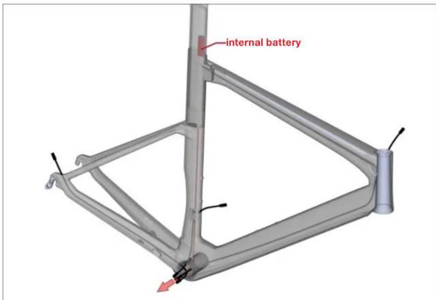
- Connect all Di2 wires coming out of the bottom bracket to the junction, please refer to Shimano installation instructions.
- Push the wires and the junction back into the bottom bracket and the seat tube.
- Install the Di2 grommets.
Headset and Fork Installation
- Note that the rear brake cable housing should be installed before installing the fork.
- Apply grease on the bearings (N°3 and 4) and on the bearing seats of the frame. Place the bearings in the frame.
- Apply grease on the fork shaft, and then slide the fork through the bearings and the head tube.
- Slide the compression ring (N^#2) over the fork shaft.
- Apply grease on the fork hinge top part then slide the top cap (N^1) over the fork shaft and over the fork hinge.
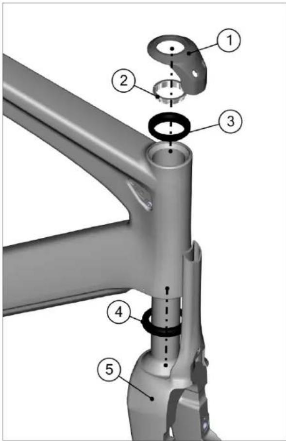
| Description Part No | ||
| Headset complete kit 212485 | ||
| 1 Top cap | ||
| 2 Compression ring | ||
| 3 Upper bearing | ||
| 4 Lower bearing | ||
| 5 Aero road fork “teamred” 212474 | ||
| Aero road fork “flame” 212475 | ||
| Aero road fork “white” 212476 | ||
| Aero road fork “stealth” 212477 |
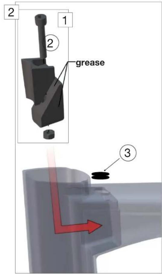
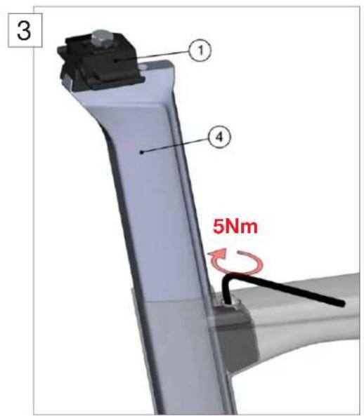
Seat clamp & seat post Installation
- Apply grease on the seat post clamp wedges as well as on the seat post clamp outer surface. Do not put grease on the seat post contact surface.
- Assemble the seat post clamp (1) and insert it into the frame (2).
- For Di2 shifting install the Di2 integrated Battery into the seat post.
- Apply carbone friction paste on the lower part of the seat post as well as on the inside of the seat tube.
- Insert the seat post into the seat tube.
- Install the saddle clamping hardware (N^1) .
- Tighten the seat post clamp bolt to 5Nm max (3).
- Install the rubber plug (^3) to close the gap on the top tube.
| Description Part N° | ||
| 1 Saddle clamp kit 212482 | ||
| 2 Seat post clamp kit 212483 | ||
| 3 Rubber plug 212484 | ||
| 4 Seat post "team red" 212478 | ||
| Seat post "flame" 212479 | ||
| Seat post "shark" 212480 | ||
| Seat post "white" 212481 | ||
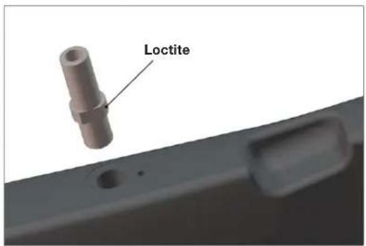
Rear brake installation
- The rear brake cable should already be installed once you start to build the rear brake, if not, refer to the first chapter.
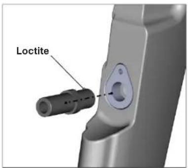
- Apply Loctite to the brake pivot thread and bolt it into the frame.
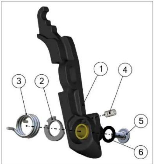
| Description Part N° | ||
| Rear brake set 212496 | ||
| 1 Brake arm | ||
| 2 Adjuster plate | ||
| 3 Spring 212499 | ||
| 4 Adjuster bolt |
- Place the adjuster plate N^2 and screw in the M4 adjustment bolt N^4 (2).
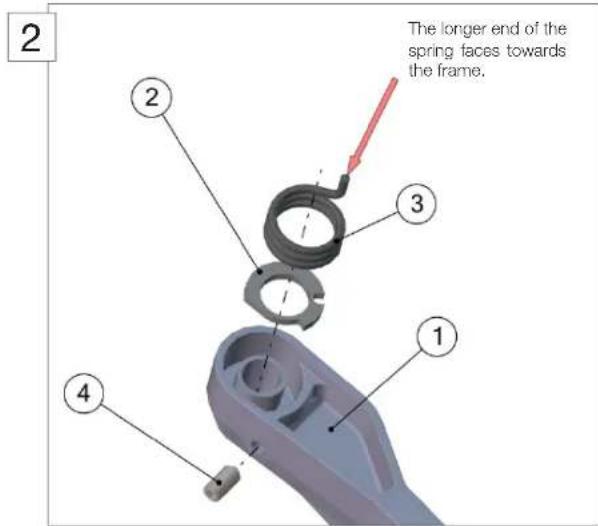
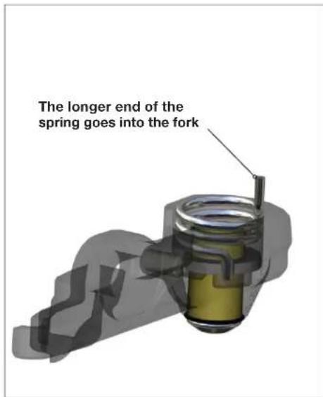
- Apply grease to the spring and place it in the brake arm. The silver spring goes in the right side brake arm. The longer end of the spring faces towards the frame (2).
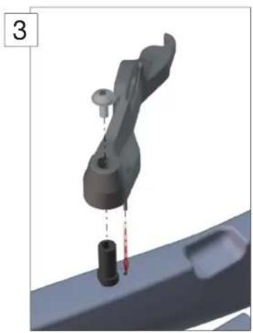
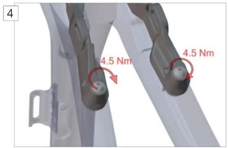
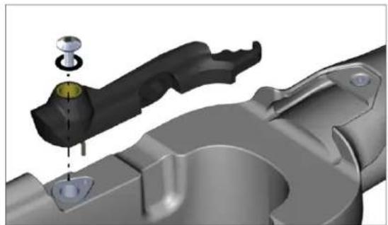
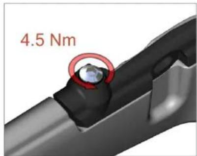
- Install the brake arm on the frame (3). Tighten the M5 bolts to 4.5Nm (4).
- Repeat steps 2 - 5 for the remaining brake arm. Note to use the dark spring for the left side brake arm.
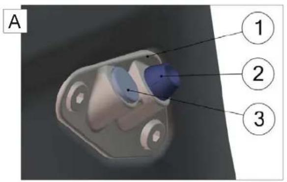
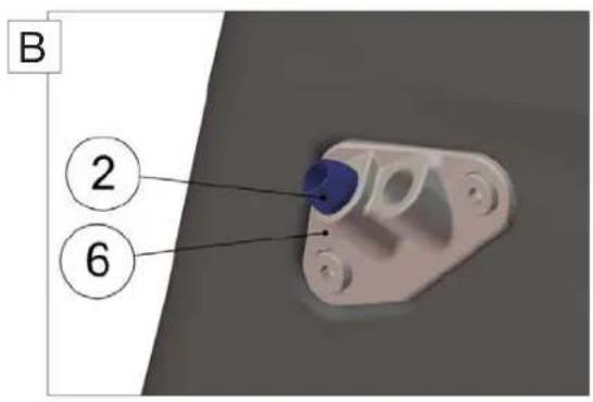
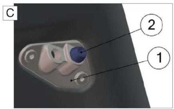
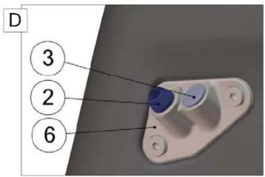
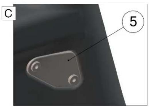
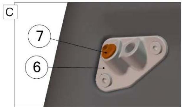
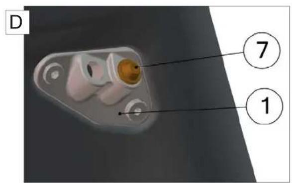
- Run the cables through the required cable guides and grommets, and then install the cable guides on the frame to close the openings at the head tube (5). The 4 possible combinations are listed below.
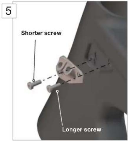
Important: Note that the shorter screw (4.5mm) goes to the front, the longer screw (8mm) goes to the back.
| Combinations / Description Required | ed parts Part N° | ||
| A | Mechanical (USA and EU standard) 1, 2, 3 | 6 212487 | |
| B | Mechanical (UK standard) | 1, 2, 3, 6 | 212487 |
| C | Di2 (USA and EU standard) 5, 6, 7 212488 | ||
| D | Di2 (UK standard) | 1, 4, 7 | 212488 |
| 2 | Shifting cable grommet (spare part) | 2 | 212490 |
| 3 | 212496 | 3 212491 | |
| 7 | Di2 grommet (spare part) | 7 | 212489 |
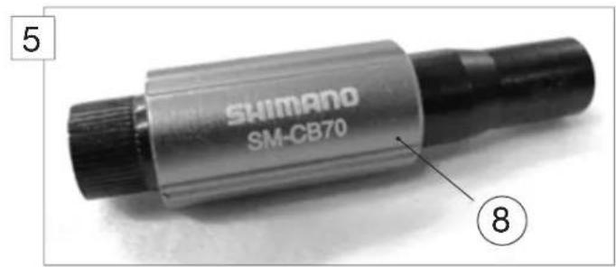
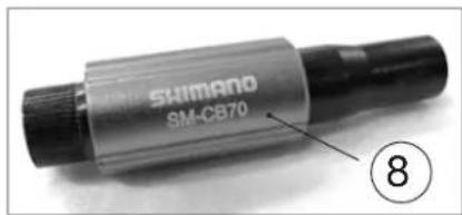
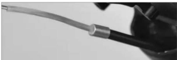
- Cut the brake cable housing 100mm from the cable guide and install the cable adjusters (N^8) . Please refer to the official Shimano installation instructions.
- Run the rear brake cable through the brake lever and the housing.
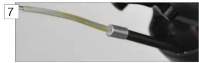
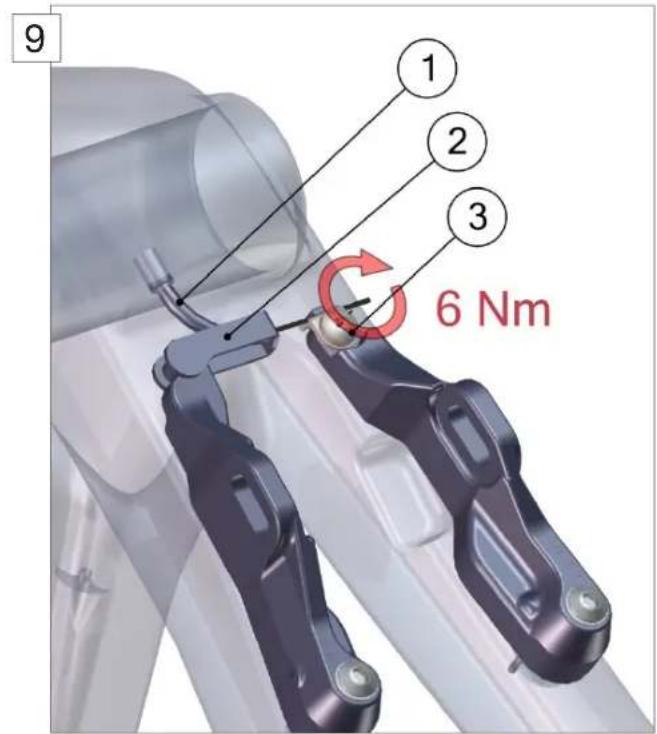
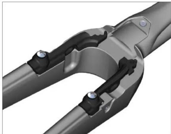
- Slide the liner of the pipe over the brake cable (7). Then slide the pipe (N^1) over the brake cable and the liner (8).
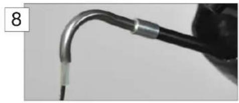
- Install the pipe holder (^2) and clamp the brake cable on the left brake arm with the T25 anchor bolt (^3) . Tighten to 6 Nm.
| Description Part N° | ||
| Rear brake set 212496 | ||
| 1 Pipe | ||
| 2 Pipe holder | ||
| 3 Anchor bolt 212499 | ||
| 8 Shimano adjusters | ||
- Install the brake pads:
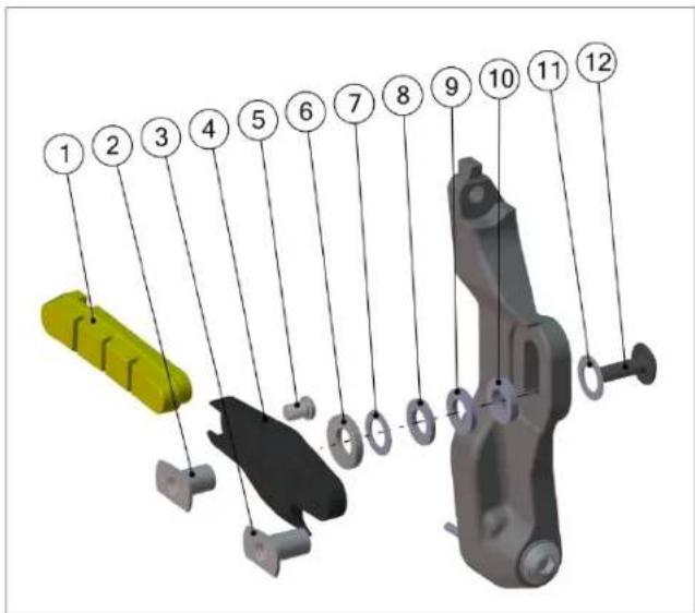
| POS | Description | Part N° |
| 1 | Brake pad | Brake shoe set: 212498 |
| 2 | Socket 10mm | |
| 3 | Socket 12mm | |
| 4 | Brake shoe | |
| 5 | Locker bolt | |
| 6 | Parabolic washer | |
| 7 | Spacer 0.5mm | |
| 8 | Spacer 1.2mm | |
| 9 | Spacer 1.5mm | |
| 10 | Spacer 2.0mm | |
| 11 | Washer | |
| 12 | Bolt M5 x 16 |
- Depending on rim dimensions, the reach of the brake pads needs to be adjusted with spacers (7, 8, 9, 10). You can use the table below as a guide.
| Rim type Rim width Spacers | per side (mm) Socket length | ||
| Zipp 303/404/808 26.5 0.5 10 | |||
| 23 2.5 10 | |||
| 22 3 10 | |||
| 21 3.5 12 | |||
| Easton EC90 SL 20.5 3.7 12 | |||
| Mavic Cosmic Carbone SL | 19 | 4.2 | 12 |
Note to only put the one washer (^11) between brake arm and brake shoe bolt (^12) .
- Please refer to the wheel manufacturer instructions for brake pad specification.
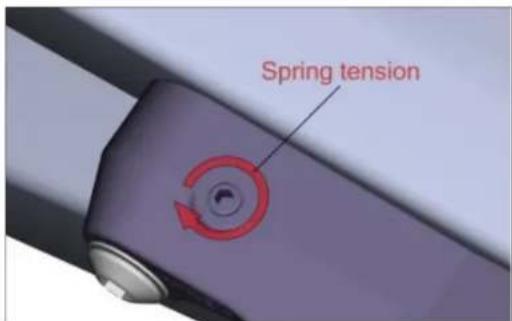
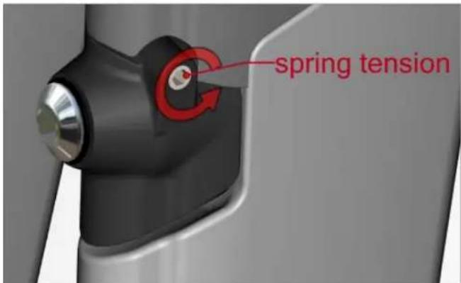
- Adjust the spring tension (M4 adjustment bolts) to achieve symmetrical pull of the brake arms.
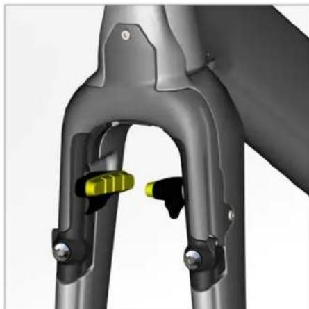
Front brake installation
- Apply Loctite to the brake pivot thread and bolt it onto the fork.
| Description Part N° | ||
| Front brake complete set 212495 | ||
| 1 Brake arm | ||
| 2 Adjuster plate | ||
| 3 Spring 212499 | ||
| 4 Adjuster bolt | ||
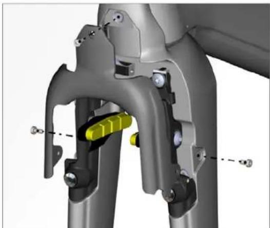
- Place the adjuster plate (N^2) into the brake arm (N^1) and screw in the M4 adjustment bolt (N^4) .
-
Apply grease to the spring (N°3) and place it in the brake arm. The silver colored spring goes into the right arm. The longest extension of the spring should point towards the fork.
-
Install the brake arm. Tighten the M5 bolt to 4.5Nm.
-
Apply Loctite to the brake pivot thread and bolt it onto the fork.
- Repeat steps 1-4 for the second brake arm.
Note to use the dark spring for the left side brake arm.
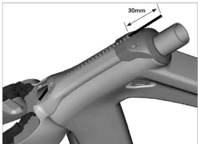
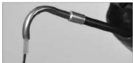
- Cut a comfortable length of Shimano brake cable housing and run it through the top cap and the fork hinge.
- Cut the brake cable housing 30mm from the top cap and install the cable adjusters. Please refer to the official Shimano installation instructions.
-
Run the front brake cable thru the housing.
-
Slide the pipe noodle over the brake cable then slide the pipe over the brake cable and the noodle.
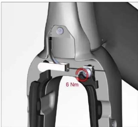
- Install the pipe holder and clamp the brake cable on the left brake arm with the T25 anchor bolt. Tighten to 6Nm.
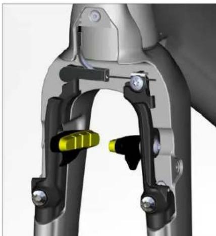
- Install the brake pads: Refer to page 14 for pad and spacer specifications.
- Install the brake cover.
- Adjust the spring tension by using the M4 adjustment bolts until the brake arms rotate symmetrical.
Notes
Notes
Notes

Inhalt
MONTAGEANLEITUNG
Einleitung 26