DE 3161 - Basket AEG-ELECTROLUX - Free user manual and instructions
Find the device manual for free DE 3161 AEG-ELECTROLUX in PDF.
| Product type | Extractor hood with retractable canopy |
| Brand | AEG-Electrolux |
| Model | DE 3161 |
| Dimensions (H x W x D) | 40 x 59.9 x 27 cm (canopy extended +21 cm) |
| Net weight | Approximately 12 kg |
| Motor power | 140 W |
| Lighting | 2 bulbs of 40 W (E14 socket) |
| Supply voltage | 220-240 V |
| Power cable length | 150 cm |
| Installation type | Built-in (under cabinet) |
| Mode of use | External evacuation or recirculation (charcoal filter optional) |
| Connection diameter | 125 mm (reduction to 100-110 mm possible) |
| Grease filter | Synthetic, to be changed every month |
| Charcoal filter | Type 29 (optional), to be replaced every 4 months |
| Minimum safety distance | 50 cm (electric hob) / 70 cm (gas) |
| Controls | Mechanical switches (lighting and motor with speed adjustment) |
| Included accessories | Screws, wall plugs, collars, spacer, hooks, deflector |
| After-sales service | Via dealer or consumer contact center |
| Spare parts available | Grease filter, charcoal filter, E14 bulbs |
| Warranty | Not specified (consult dealer) |
Frequently Asked Questions - DE 3161 AEG-ELECTROLUX
User questions about DE 3161 AEG-ELECTROLUX
0 question about this device. Answer the ones you know or ask your own.
Ask a new question about this device
Download the instructions for your Basket in PDF format for free! Find your manual DE 3161 - AEG-ELECTROLUX and take your electronic device back in hand. On this page are published all the documents necessary for the use of your device. DE 3161 by AEG-ELECTROLUX.
USER MANUAL DE 3161 AEG-ELECTROLUX
natural_image
Technical diagram of a mechanical assembly with two views and close-ups of internal components (no text or symbols)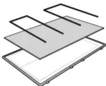
natural_image
Diagram of layered electronic components or layers with no visible text or symbolsBild 3
Aktivkohlefilter
natural_image
Diagram of a printer front panel with a magnified inset showing the printer's internal structure (no text or symbols present)Bild 5
Reinigung
1 Schraubenschlüssel
1 Verbindungsring
2 Träger/Halter
2 Ansatzhaken
1 Deflektor
2 Federringe
natural_image
Technical diagram of a mechanical component with two circular insets showing internal components, labeled 'Bild 8' (no text or symbols on the diagram itself)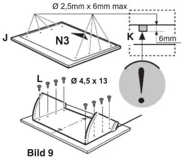
text_image
Ø 2,5mm x 6mm max J N3 K 6mm L Ø 4,5 x 13 Bild 9
text_image
M1 M1 M2 M2 Bild 10Installation
text_image
R N1 Ø 5 x 45 R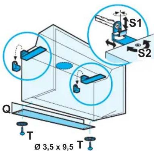
text_image
Q T Ø 3,5 x 9,5 T S1 S2Geachte klant,
text_image
Technical diagram of an air fan assembly with labeled components and directional arrows indicating flow or movement.natural_image
Diagram of a printer front panel with a magnified inset showing the printer's internal structure (no text or symbols present)afb. 5
Reiniging
natural_image
Technical line drawing of a mechanical component with two circular insets showing internal components (no text or symbols)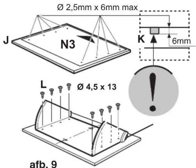
text_image
Ø 2,5mm x 6mm max J N3 K 6mm L Ø 4,5 x 13 afb. 9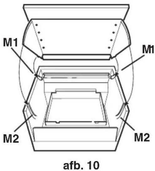
text_image
M1 M1 M2 M2 afb. 10Installatie
text_image
R N1 Ø 5 x 45 R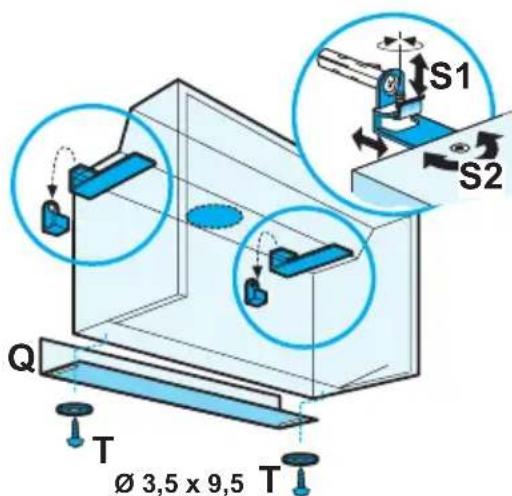
text_image
S1 S2 Q T Ø 3,5 x 9,5 Tafb. 12
Chère cliente, cher client,
natural_image
Diagram of a crane lifting a box against a brick wall, showing airflow direction (no text or symbols)Fig. 2
natural_image
Technical diagram showing mechanical assembly and assembly steps with no visible text or symbolsFig. 3
Filtre à charbon
text_image
Technical diagram of a mechanical device with labeled components and directional arrows indicating flow or movement.natural_image
Diagram of a printer's front panel and side panel with a magnified inset showing the printer's internal structure (no text or symbols present)Fig. 5
Nettoyage
natural_image
Technical diagram of a mechanical component with two circular insets showing internal force directions (labeled 'I'), labeled as Fig. 8 (no text or symbols on the diagram itself)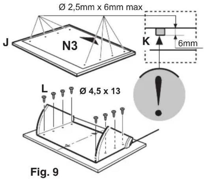
text_image
Ø 2,5mm x 6mm max J N3 K 6mm L Ø 4,5 x 13 Fig. 9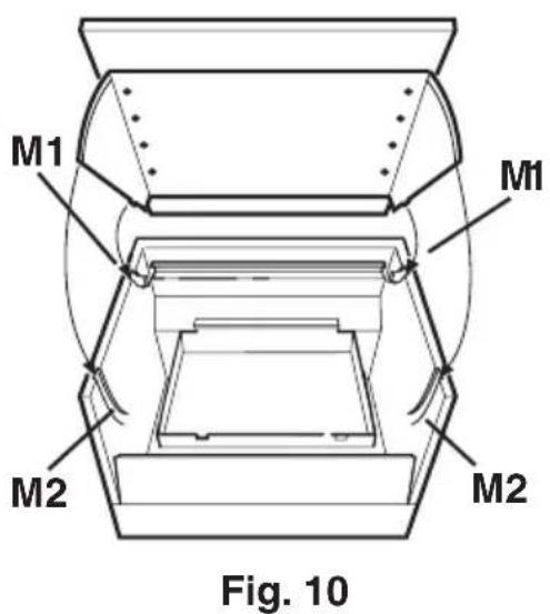
text_image
M1 M1 M2 M2 Fig. 10Installation de la hotte
text_image
R N1 Ø 5 x 45 R
text_image
S1 S2 Q T Ø 3,5 x 9,5 TFig. 12
Contents
Safety warnings 51
Description of the Appliance 53
Extraction mode 53
Recirculation mode 53
Control Panel 54
Maintenance and Care 55
Paper grease filter 55
Charcoal filter 56
Changing the light bulbs 57
Cleaning the hood 57
Special accessories....57
Something Not Working....58
Technical assistance service 59
Service and Spare Parts 59
Customer Care Department 60
Technical Details 61
Mounting accessories included 61
Electrical connection 62
Before beginning installation 63
Fixing a furniture door to the visor 65
Fixing the hood 66
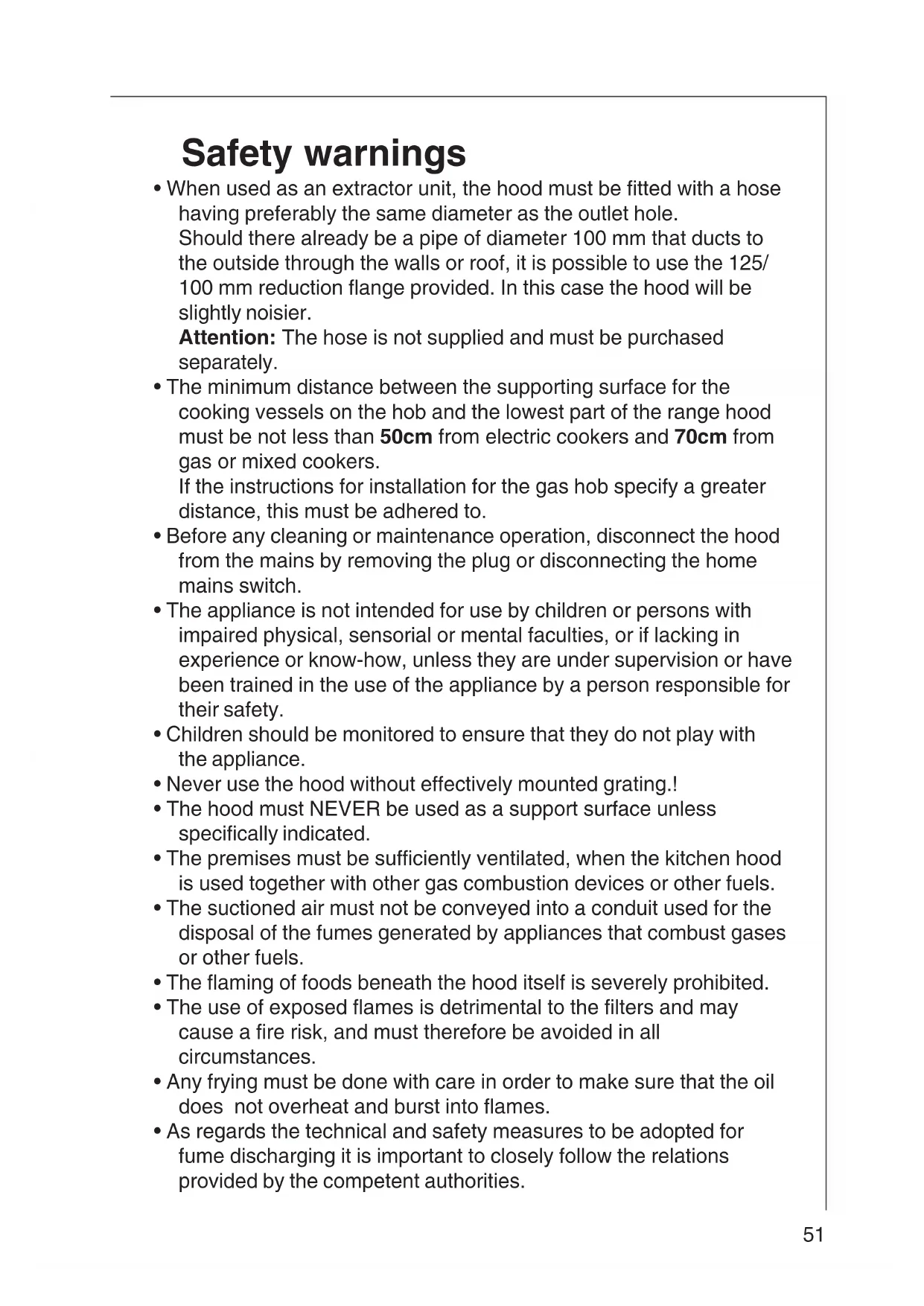
Safety warnings
- When used as an extractor unit, the hood must be fitted with a hose having preferably the same diameter as the outlet hole.
Should there already be a pipe of diameter 100 mm that ducts to the outside through the walls or roof, it is possible to use the 125/100 mm reduction flange provided. In this case the hood will be slightly noisier.
Attention: The hose is not supplied and must be purchased separately.
- The minimum distance between the supporting surface for the cooking vessels on the hob and the lowest part of the range hood must be not less than 50cm from electric cookers and 70cm from gas or mixed cookers.
If the instructions for installation for the gas hob specify a greater distance, this must be adhered to.
- Before any cleaning or maintenance operation, disconnect the hood from the mains by removing the plug or disconnecting the home mains switch.
- The appliance is not intended for use by children or persons with impaired physical, sensorial or mental faculties, or if lacking in experience or know-how, unless they are under supervision or have been trained in the use of the appliance by a person responsible for their safety.
- Children should be monitored to ensure that they do not play with the appliance.
- Never use the hood without effectively mounted grating.!
- The hood must NEVER be used as a support surface unless specifically indicated.
- The premises must be sufficiently ventilated, when the kitchen hood is used together with other gas combustion devices or other fuels.
- The suctioned air must not be conveyed into a conduit used for the disposal of the fumes generated by appliances that combust gases or other fuels.
- The flaming of foods beneath the hood itself is severely prohibited.
- The use of exposed flames is detrimental to the filters and may cause a fire risk, and must therefore be avoided in all circumstances.
- Any frying must be done with care in order to make sure that the oil does not overheat and burst into flames.
- As regards the technical and safety measures to be adopted for fume discharging it is important to closely follow the relations provided by the competent authorities.
- The hood must be regularly cleaned on both the inside and outside (AT LEAST ONCE A MONTH, it is in any event necessary to proceed in accordance with the maintenance instructions provided in this manual)..
- Failure to follow the instructions as concerns hood and filter cleaning will lead to the risk of fires.
- Do not use or leave the hood without the lamp correctly mounted because of the possible risk of electric shocks.
- We decline any responsibility for any problems, damage or fires caused to the appliance as the result of the non-observance of the instructions included in this manual.
This appliance is marked according to the European directive 2002/96/EC on Waste Electrical and Electronic Equipment (WEEE).
By ensuring this product is disposed of correctly, you will help prevent potential negative consequences for the environment and human health, which could otherwise be caused by inappropriate waste handling of this product.

The symbol on the product, or on the documents accompanying the product, indicates that this appliance may not be treated as household waste. Instead it should be taken to the appropriate collection point for the recycling of electrical and electronic equipment. Disposal must be carried out in accordance with local environmental regulations for waste disposal.
For more detailed information about treatment, recovery and recycling of this product, please contact your local council, your household waste disposal service or the shop where you purchased the product.
Description of the Appliance
- The cooker hood is designed to extract unpleasant odours from the kitchen, it will not extract steam.
- The hood is supplied as an extractor unit and can also be used in recirculation mode by fitting a charcoal filter.
Extraction mode
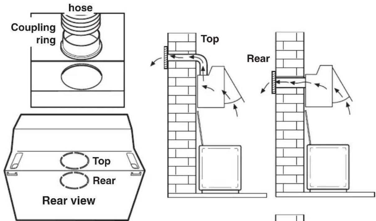
- In this mode fumes are extracted to the outside via a hose connected to the coupling ring. Fig. 1
Note: The coupling ring may be placed on the top or on the rear exhaust according to the needs. - In order to obtain the best performance the hose should have a diameter equal to the outlet hole.
text_image
hose Coupling ring Top Rear Rear view Top RearFig. 1
Recirculation mode
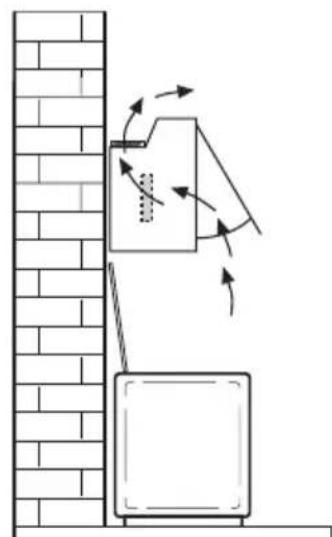
• The air is filtered through a charcoal filter and returned to the kitchen. Fig. 2
- You will need an original charcoal filter for the recirculation mode. (See Special Accessories).
Attention!
341 D: two charcoal filters
DE 3161: one charcoal filter
natural_image
Diagram showing airflow around a wall-mounted device with directional arrows (no text or symbols)Fig. 2
Control Panel
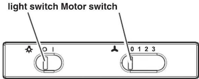
- Best results are obtained by using a low speed for normal conditions and a high speed when odours are more concentrated. Turn the hood on a few minutes before you start cooking. The hood should be left on after cooking for about 15 minutes or until all the odours have disappeared. The control switches are located on the unit's front panel:
- the light switch switches the hood lamp on and off - the motor switch switches the motor on and off, enabling you to select one of the different speeds.
The hood is also equipped with a micro-switch which can be found under the lower runner of the visor on the right hand side.
With this micro-switch, the appliance may be automatically switched on and off by opening and closing the pull-out panel, but only if the fan speed has already been set and the light switch is turned to "I".
text_image
light switch Motor switch 0 1 0 1 2 3Maintenance and Care
- Before performing any maintenance operation, isolate the hood from the electrical supply by switching off at the connector and removing the connector fuse.
Or if the appliance has been connected through a plug and socket, then the plug must be removed from the socket.
Paper grease filter
- The purpose of the grease filters is to absorb grease particles which form during cooking and it must always be used, either in the external evacuation or internal recycling function.
The paper grease filter is very thin (approx. 1 mm) and positioned on the inside of its related support grille.
The filter should be changed once a month.
- The grille should be cleaned with luke warm water and non-abrasive detergent when you change the filter.
- The grease filter can be ordered from your local Service Force Centre.
Opening the grille
Open the latch and remove the grille downwards. Fig. 3
Removing the filter
Remove the stops to take out the filter. Fig. 3
- Clean the inner housing using a hand hot solution only(never use caustic detergents, abrasive powders or brushes).
natural_image
Technical diagram showing mechanical assembly and assembly steps with no visible text or symbolsFig. 3
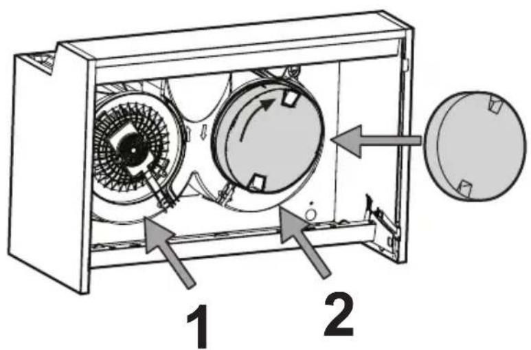
Charcoal filter
- The charcoal filter should only be used if you want to use the hood in recirculation mode. - The charcoal filter cannot be washed nor regenerated.
The charcoal filter should be replaced every 4 months under normal use.
Replacement filters are available from your local Service Force Centre.
Fitting - Fig. 4
Remove the grille.
Place the charcoal filter to cover the grill that protects the extraction motor so that the slots on the filter correspond to the pins on the sides of the motor protection grill.
Turn the filter clockwise in order to lock the filter into position.
Remount the grille.
• To remove proceed in the reverse order.
• Always specify the hood model code number and serial number when ordering replacement filters. This information is shown on the rating plate located on the inside of the unit.
- The charcoal filter can be ordered from your local Service Force Centre.
text_image
Technical diagram of an air conditioning unit with labeled components and directional arrows indicating flow or movement.Fig. 4 - 341 D: two charcoal filters
DE 3161: one charcoal filter

Warning
- Failure to observe the instructions on cleaning the unit and changing the filters will cause a fire hazard. You are therefore strongly recommended to follow these instructions.
- The manufacturer declines all responsibility for any damage to the motor or any fire damage linked to inappropriate maintenance or failure to observe the above safety recommendations.
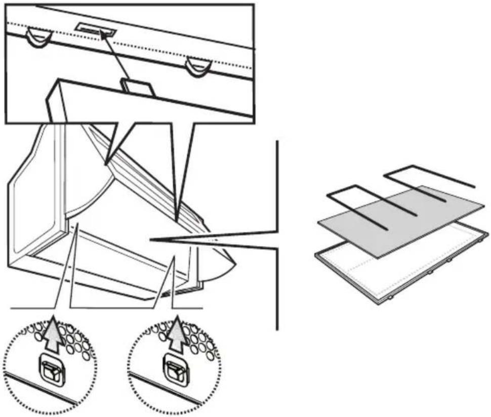
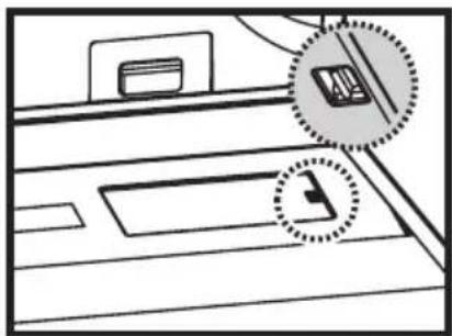
Changing the light bulbs
- Disconnect the cooker hood from the mains supply. Prior to touching the light bulbs ensure they are cooled down.
- Extract the extractable drawer.
- Remove the grille
Note: lamps are accessible also by removing the light shield, these are supplied with side lock/unlock plastic spring, grasp it to remove the light shield. Fig. 5
- Replace the old bulb with a new one of the same type.
- Refit the lamp cover/grille.
- If the light does not come on, make sure the bulb has been inserted correctly before contacting your local Service Force Centre.
natural_image
Diagram of a printer or printer with two circular annotations highlighting the components (no text or symbols present)Fig. 5
Cleaning the hood
- Clean the outside of the hood using a damp cloth and a solution of water and mild washing up liquid.
- Never use corrosive, abrasive or flammable cleaning products or products containing bleach.
- Never insert pointed objects in the motor's protective grid.
- Only ever clean the switch panel and filter grill using a damp cloth and mild washing up liquid.
- Clean all the plastic parts with a soft cloth soaked in warm water and neutral soap.
- It is extremely important to clean the unit and change the filters at the recommended intervals. Failure to do so will cause grease deposits to build up that could constitute a fire hazard.
Special accessories
Charcoal filter type 29 Attention!
341 D: two charcoal filters
DE 3161: one charcoal filter
Something Not Working
If your appliance fails to work properly please carry out the following checks.
| Symptom Solution | |
| The cooker hood Check will not start... the electricity supply. | that: The hood is connected to city supply.Check that a fan speed has been selected |
| The cooker hood Check is not working high enough | that: The fan speed is set for the task.The grease filters are clean.The kitchen is adequately vented to allow the entry of fresh air.If set up for recirculation, check that the charcoal filter is still effective.If set up for extraction, check that the ducting and outlets are not blocked. |
| The cooker hood has switched off tripped. during operation... Turn | the safety cut-out device has been off the hob and then wait for the device to reset.If the hood has been installed below the heights indicated in the installation instructions the motor will cut-out frequently which will damage the hood. |
If after all these checks, the problem persists, contact your local Service Centre, quoting the model and serial number.
Please note that it will be necessary to provide proof of purchase for any in-guarantee service calls.
In-guarantee customers should ensure that the above checks have been made as the engineer will make a charge if the fault is not a mechanical or electrical breakdown.
Technical assistance service
You are welcome to telephone our technical assistance service (see list of technical assistance centres) whenever you need information or in the unlikely event of a fault.
We reserve the right to change specifications and colours as a result of our policy of continuing technological development.
Service and Spare Parts
In the event of your appliance requiring service, or if you wish to purchase spare parts, contact your local Service Force Centre by telephoning: 08705 929 929
Your call will be automatically routed to the Service Centre covering your post code area. For the address of your local Service Force Centre and further information about Service Force, please visit the website at www.serviceforce.co.uk Please ensure that you have read the section "What to do if..." as the engineer will make a charge if the fault is not a mechanical or electrical breakdown even the appliance is under warranty. Please note that proof of purchase is required for in-guarantee service calls.
Help us to help you
Please determine your type of enquiry before writing or telephoning.
When you contact us we need to know:
- Your name • Clear and concise details of the fault
- Address and post code • Name and model of the appliance*
- Telephone number • E number*
- Serial number*
* This information can be found on the rating plate, which can be seen when the grease filters are removed.
If you require Customer Service in the Republic of Ireland please contact us at the address below:
AEG
Electrolux Group (Ire) Ltd
Long Mile Road
Dublin 12
Republic of Ireland
Tel: +353 (0) 1 4090751
Email: service.eid@electrolux.ie
If you require Customer Service in the Republic of Ireland please contact us at the address below:
AEG
Electrolux Group (Ire) Ltd
Long Mile Road
Dublin 12
Republic of Ireland
Tel: +353 (0) 1 4090751
Email: service.eid@electrolux.ie
CUSTOMER CARE DEPARTMENT
For general enquiries concerning your AEG appliance or for further information on AEG products, please contact our Customer Care Department by letter or telephone at the address below or visit our website at www.aeg.co.uk
Customer Services Department
Major Appliances
AEG Electrolux
Addington Way
Luton
Bedfordshire
LU4 9QQ
08705 350 350 (*)
* calls to this number may be recorded for training purposes
Technical Details
341 D DE 3161
Dimensions (in cm):
Height: 40 40
Width: 59,9 59,9
Depth: 27 (+21) 27 (+21)
Maximum absorbed power: 380 W 220 W
Motor: 2 x 150 W 140 W
Lighting: 2 x 40 W (E14) 2 x 40 W (E14)
Electrical connection: 220-240 V 220-240 V
Length of the cable: 150 cm 150 cm
Fuse rating: 5A T 5A T
Mounting accessories included
1 allen spanner (for TORX screws).
1 spacer
2 brackets
2 hooks
1 deflector
2 plastic washers for the spacer
2 wall plugs
1 screw 2.9x9.5 to affix the deflector/coupling ring on the outlet hole
4 screws 4.5 x 16 (to affix the cooker hood sideways)
8 screws 4.5 x 13 (to affix a wooden panel to the cabinet door).
2 screws 3.5 x 9.5 (to affix the spacer to the cooker hood)
2 screws 5 x 45 (fixing the hooks)
1 flange ∅ 120 mm
1 reduction flange ∅ 100-110-125
2 screws 5x18
2 screws 5x10 to fix the brackets
2 bushes to fix the brackets
Electrical connection
Safety warnings for the electrician
The mains power supply must correspond to the rating indicated on the plate situated inside the hood. If provided with a plug connect the hood to a socket in compliance with current regulations and positioned in an accessible area. If it not fitted with a plug (direct mains connection) or if the plug is not located in an accessible area apply a bi-polar switch in accordance with standards which assures the complete disconnection of the mains under conditions relating to over-current category III, in accordance with installation instructions.
IMPORTANT: Before re-connecting the hood circuit to the mains supply and checking the efficient function, always check that the mains cable is correctly assembled.
IMPORTANT! Power cable replacement must be undertaken by the authorized service assistance centre or similar qualified person.
Before beginning installation
- Warning! Do not connect the appliance to the mains until the installation is fully complete.
- Remove and keep the grille.
Note: This is to be mounted once installation is completed.
- In addition check whether near the installation area of the hood (in the area accessible also with the hood mounted) an electric connection to the mains is available and if it is possible to connect a fumes discharge device to the outside (Extraction mode only).
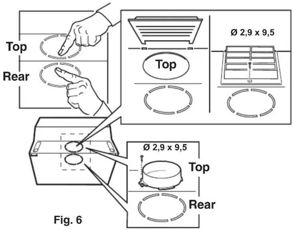
- Choose the exhaust hole to use- Fig. 6:
Only recirculation mode: use ONLY the top exhaust hole.
Check that this, once installation is completed, is not obstructed and that there is sufficient space so that the purified fumes and steam can return easily into the kitchen.
Press with decision to take away the prefractured part (Top or Rear) that closes the exhaust hole and remove it.
Install the connection ring on the open discharge outlet (bayonet attachment - (Extraction mode only) or the deflector. (recirculation mode only).
text_image
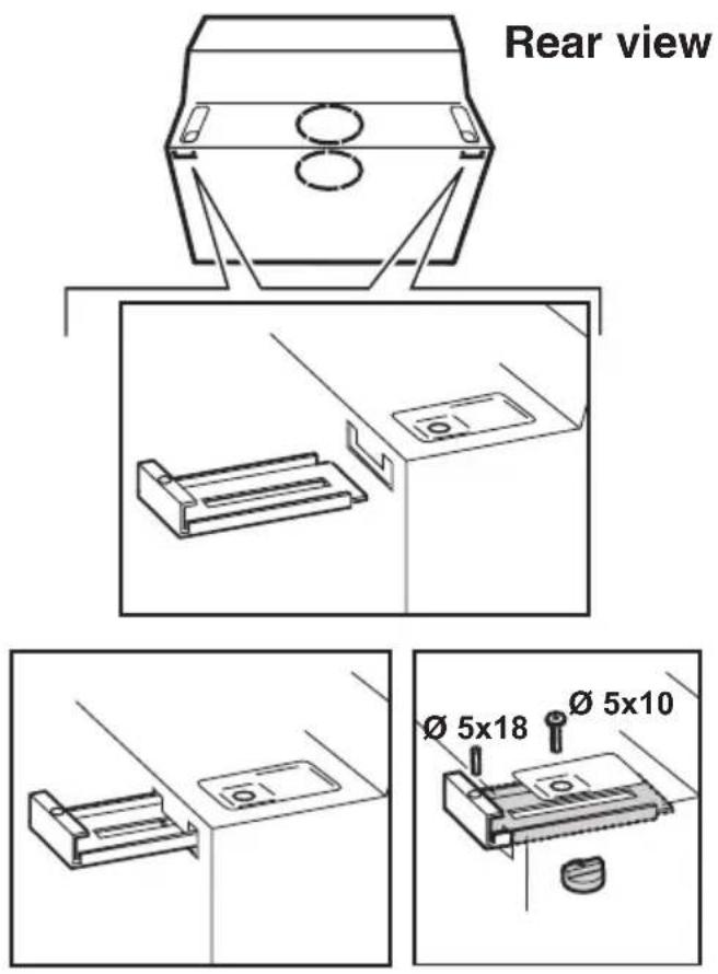
Top Rear Ø 2,9 x 9,5 Top Ø 2,9 x 9,5 Top Rear Fig. 6- Check that the side wall units between which to install the hood are sufficiently heavy for installing the hood.
Otherwise mount the brackets to use as additional supports:
a. Insert each bracket from the rear inside the hood through the opposite slots.
b. Fix the brackets with the screws and threaded bushes.
Screw the headless screws halfway.
They will serve to adjust the position of the hood at the moment of installation. Fig. 7
Note: the position of the brackets can be adjusted during installation, suitably loosening and retightening the screws that fix them to the hood.
text_image
Rear view Ø 5x18 Ø 5x10Fig. 7
Fixing a furniture door to the visor
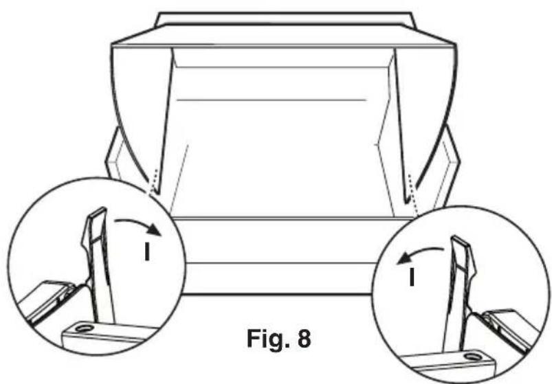
- Remove the visor (freeing the locking releases Fig. 8, I).
- Apply the drill holes diagram N3 on the rear of the furniture door (Fig. 9, J-the arrow on the diagram should face the upper border of the furniture door), perform blind holes as indicated (K-Fig. 9).
- Place the visor over the furniture door and affix with 8 screws (Fig. 9,L).
- Refit the cover on the cooker hood firstly in the upper track (Fig. 10-M1), then in the lower track (Fig. 10-M2).
natural_image
Technical line drawing of a mechanical component with two circular insets showing internal components (no text or symbols)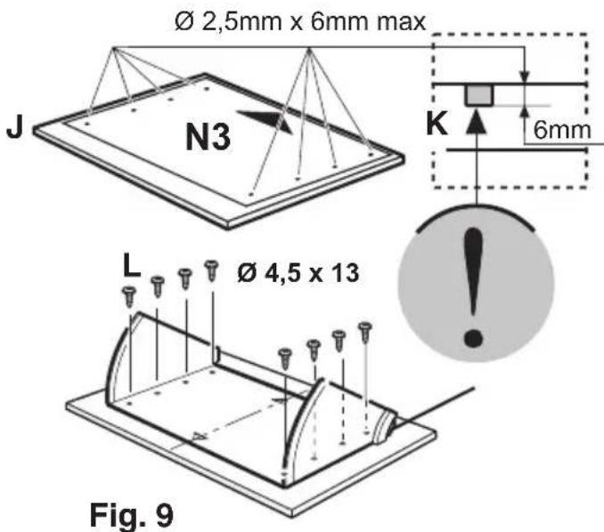
text_image
Ø 2,5mm x 6mm max J N3 K 6mm L Ø 4,5 x 13 Fig. 9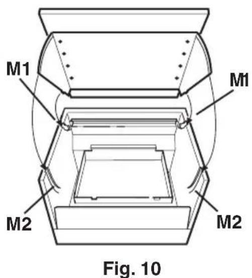
text_image
M1 M1 M2 M2 Fig. 10Fixing the hood
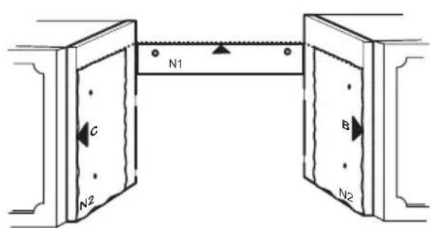
- Use template N2. Position the template on the front edges of the wall unit (right wall unit, B side) – (left wall unit, C side) WITHOUT CONSIDERING THE THICKNESS OF THE FRONT WALL UNIT DOORS, and make the holes as indicated. Fig. 11
- If the side wall units are not heavy enough ONLY:
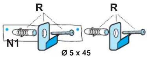
a. If necessary, fix the hood to the wall, putting template N1 on the wall so its upper edge coincides with the upper edge of template N2. Fig. 11-12
b. Make the holes as indicated.
Fix 2 hooks R to the wall with screws and dowels. Fig. 12
c. Hang the hood onto the hooks and adjust the position of the hood with headless screws S1 and adjusting the position of the hooking brackets with screws S2. Fig. 12
• Fix the hood to the side wall units with 4 screws P. Fig. 11
- Mount the lower corner Q (*) to the hood with two screws and plastic washers T. They will serve to cover possible spaces between the rear of the hood and the wall. Fig. 11-12
- Fit the grille.
text_image
N1 C N2 B N2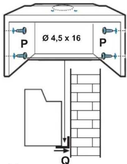
text_image
Ø 4,5 x 16 P P QFig. 11
text_image
R N1 Ø 5 x 45 R
text_image
S1 S2 Q T Ø 3,5 x 9,5 TFig. 12