C2 - Exercise bike Batavus - Free user manual and instructions
Find the device manual for free C2 Batavus in PDF.
| Product type | Exercise bike |
| Brand and model | Batavus C2 |
| Dimensions (L x W x H) | 102 cm x 55 cm x 146 cm |
| Weight | 37 kg |
| Maximum user weight | 135 kg |
| Power supply | 230 V / 115 V via transformer |
| Main functions | Manual program (8 levels), 10 training profiles, measurements of time, speed, distance, RPM, calories, heart rate, scan mode display |
| Heart rate measurement | Hand sensors, ear clip (optional) or wireless chest strap (optional) |
| Display | LCD screen with backlight, displays time, date, ambient temperature |
| Resistance | 8 adjustable levels via +/- keys |
| Training programs | Manual (M) and profiles (P) with 10 different profiles |
| Assembly | Requires 2 people, tools provided in assembly kit |
| Maintenance and cleaning | Wipe with a soft, absorbent cloth after each use; do not use detergent; regularly check tightness of screws and nuts |
| Safety | Consult a doctor before any exercise; do not use outdoors; flat and stable surface; do not ride with multiple people |
| Spare parts and repairability | Contact the seller or Batavus distributor for any defective parts; 24-month warranty for domestic use |
| Operating temperature | 10°C to 35°C |
| Storage temperature | -15°C to 40°C |
| Maximum humidity | 90% |
| Compliance | EU EMC directives (89/336/EEC), EN-957 standard, CE marking |
| Appliance class | Domestic use |
Frequently Asked Questions - C2 Batavus
User questions about C2 Batavus
0 question about this device. Answer the ones you know or ask your own.
Ask a new question about this device
Download the instructions for your Exercise bike in PDF format for free! Find your manual C2 - Batavus and take your electronic device back in hand. On this page are published all the documents necessary for the use of your device. C2 by Batavus.
USER MANUAL C2 Batavus
OWNER'S MANUAL P. 2-10
MANUALE D'USO P. 38-47
MANUAL DEL USUARIO P. 48-55
BRUKSANVISNING S. 56-63
KÄYTTÖOHJE S. 64-71
text_image
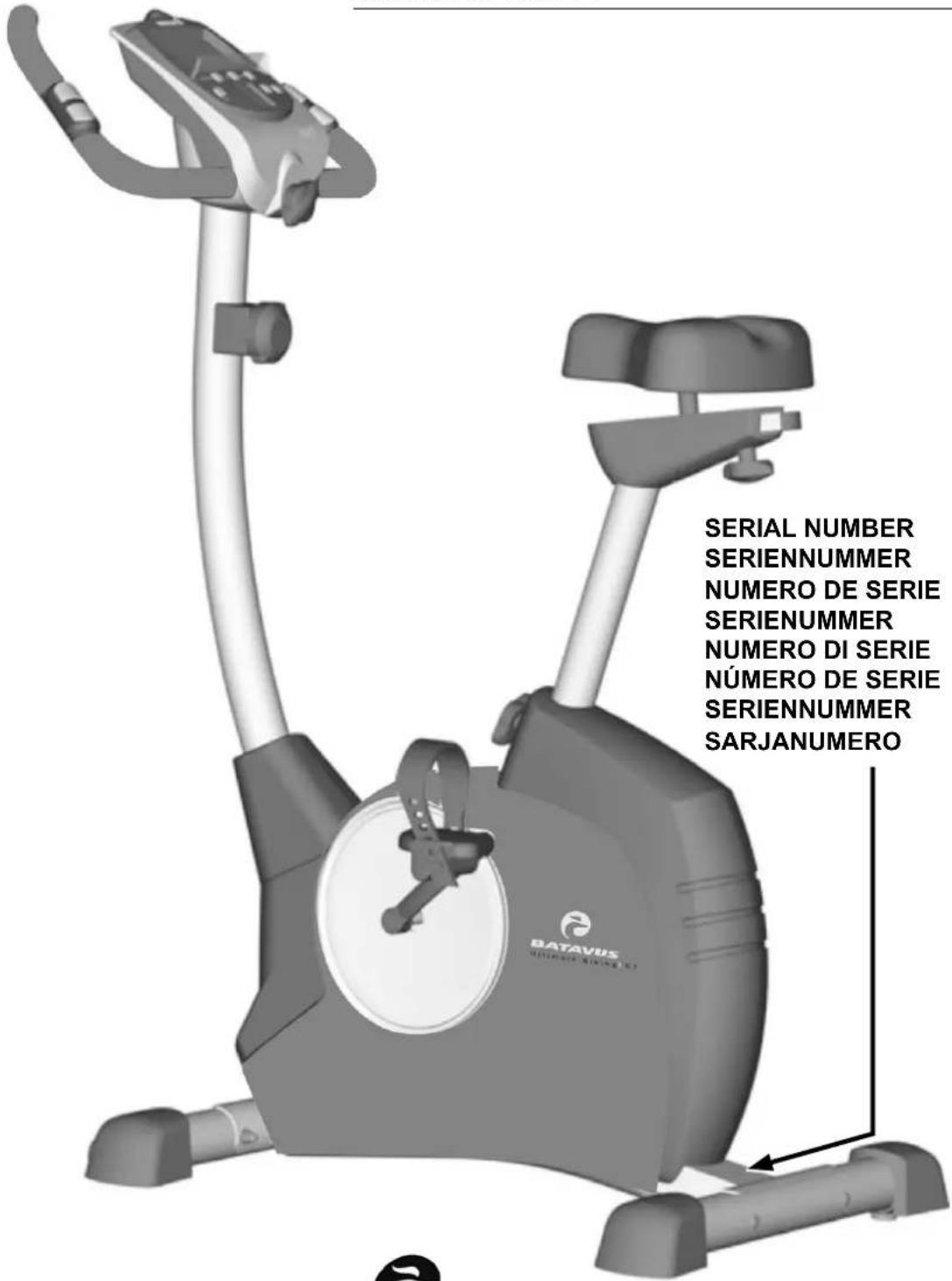
SERIAL NUMBER SERIENNUMMER NUMERO DE SERIE SERIENUMMER NUMERO DI SERIE NUMERO DE SERIE SERIENUMMER SARJANUMEROBATAVUS
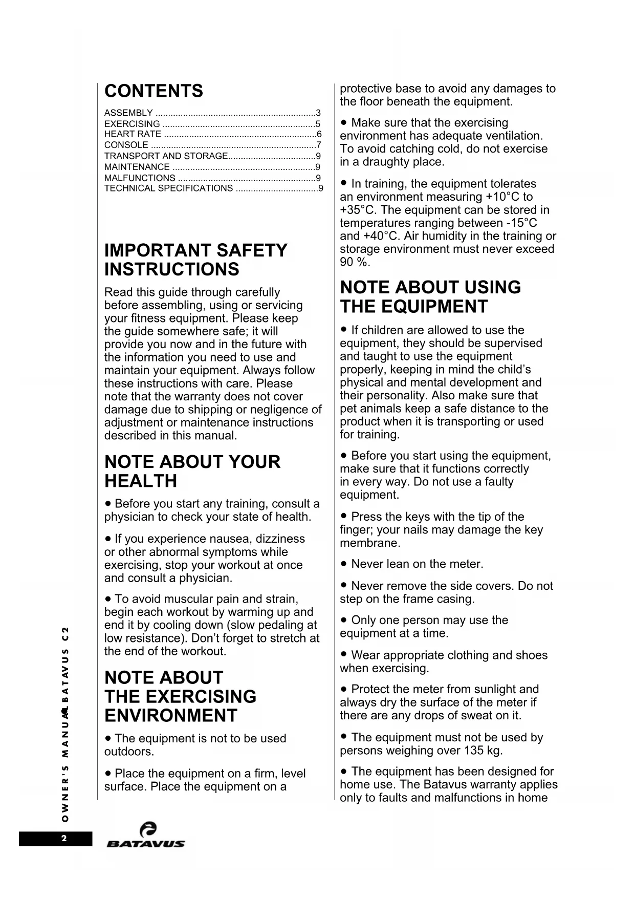
CONTENTS
ASSEMBLY 3
EXERCISING 5
HEART RATE 6
CONSOLE 7
TRANSPORT AND STORAGE....9
MAINTENANCE 9
MALFUNCTIONS 9
TECHNICAL SPECIFICATIONS 9
IMPORTANT SAFETY INSTRUCTIONS
Read this guide through carefully before assembling, using or servicing your fitness equipment. Please keep the guide somewhere safe; it will provide you now and in the future with the information you need to use and maintain your equipment. Always follow these instructions with care. Please note that the warranty does not cover damage due to shipping or negligence of adjustment or maintenance instructions described in this manual.
NOTE ABOUT YOUR HEALTH
- Before you start any training, consult a physician to check your state of health.
- If you experience nausea, dizziness or other abnormal symptoms while exercising, stop your workout at once and consult a physician.
- To avoid muscular pain and strain, begin each workout by warming up and end it by cooling down (slow pedaling at low resistance). Don't forget to stretch at the end of the workout.
NOTE ABOUT THE EXERCISING ENVIRONMENT
- The equipment is not to be used outdoors.
- Place the equipment on a firm, level surface. Place the equipment on a
protective base to avoid any damages to the floor beneath the equipment.
- Make sure that the exercising environment has adequate ventilation. To avoid catching cold, do not exercise in a draughty place.
- In training, the equipment tolerates an environment measuring +10°C to +35°C. The equipment can be stored in temperatures ranging between -15°C and +40°C. Air humidity in the training or storage environment must never exceed 90%.
NOTE ABOUT USING THE EQUIPMENT
- If children are allowed to use the equipment, they should be supervised and taught to use the equipment properly, keeping in mind the child's physical and mental development and their personality. Also make sure that pet animals keep a safe distance to the product when it is transporting or used for training.
- Before you start using the equipment, make sure that it functions correctly in every way. Do not use a faulty equipment.
- Press the keys with the tip of the finger; your nails may damage the key membrane.
- Never lean on the meter.
- Never remove the side covers. Do not step on the frame casing.
- Only one person may use the equipment at a time.
- Wear appropriate clothing and shoes when exercising.
- Protect the meter from sunlight and always dry the surface of the meter if there are any drops of sweat on it.
- The equipment must not be used by persons weighing over 135 kg.
- The equipment has been designed for home use. The Batavus warranty applies only to faults and malfunctions in home
use (24 months). Further information on warranty terms can be obtained from your national Batavus distributor. Please note that the warranty terms may vary from one country to another.
- Do not attempt any servicing or adjustments other than those described in this guide. Everything else must be left to someone familiar with the maintenance of electromechanical equipments and authorised under the laws of the country in question to carry out maintenance and repair work.
SAVE THIS INSTRUCTION MANUAL
ASSEMBLY
Start by unpacking the equipment. Two people are needed for the assembly.
Assembly kit (contents marked with * in the spare part list): keep the assembly tools, as you may need them e.g. for adjusting the equipment
If necessary, please contact your dealer with the model, equipment serial no. and spare part no. of the missing part. You'll find a spare part list at the back of this guide. The packaging includes a silicate bag for absorbing moisture during storage and transportation. Please dispose of the bag once you have unpacked the equipment. The directions left, right, front and back are defined as seen from the exercising position. Allow at least 100 cm of clearance around the equipment. We also recommend opening the package and assembling the product on a protective base.
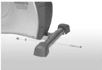
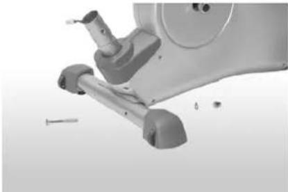
REAR AND FRONT SUPPORT
natural_image
Close-up of a medical or laboratory device with a rod and mechanical lever (no visible text or symbols)Mount the rear foot tube to the base frame using the screws, the washers and the cap nuts.
natural_image
Close-up of a white exercise machine foot with visible joints and a small screw, no text or symbols present.Mount the front foot tube to the base frame in the same way. Make sure that the rollers for the foot caps face forward and down during assembly
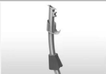
FRONT TUBE
natural_image
3D rendered image of a mechanical tool or connector with a black handle and metallic end (no text or symbols visible)Push the console cap, which will later be mounted beneath the console, and the tube cover for the handlebar shaft onto the handlebar shaft. Then, push the foam ring for the tube cover onto the handlebar shaft and push upward.
natural_image
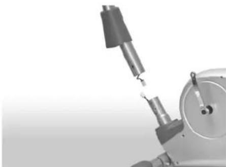
Close-up of a robotic arm with a mechanical tool inserted, showing no visible text or symbols.Connect the top cable to the bottom cable protruding from the frame tube of the base frame.
natural_image
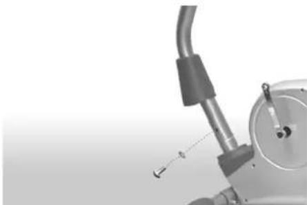
Mechanical assembly diagram showing a pipe fitting with a curved handle and shaft (no text or symbols)Place the handlebar shaft onto the frame tube on the base frame and fasten it using the screws and the washers. CAUTION: Do not pinch the cable! Push the tube cover together with the housing foam ring downward onto the housing.
HANDLEBAR
natural_image
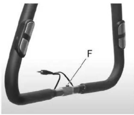
Close-up of a black curved pipe with attached cable and connector, labeled 'F' (no text or symbols beyond label)
text_image
H E GAssemble the handlebar tube together with the handlebar clamp, the screw, the washer, the spacer sleeve and the hand wheel for adjusting the handlebars. To do this, place the handlebar tube into the mount (E) on the handlebar shaft. CAUTION: The pin (F) for the handlebar tube must be inserted into the groove (G). Then push the handlebar clamp over the handlebar tube and first loosely insert the lower screw with the washer. The handlebar clamp should uniformly wrap around the handlebar tube. CAUTION: Do not pinch the cable! Insert the spacer sleeve into the upper hole and tighten. Next, push the cable for the hand pulse sensors through the opening (H) beneath the mounting plate and thread it upward out of the handlebar shaft.
CONSOLE
text_image
J i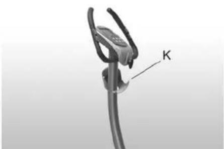
natural_image
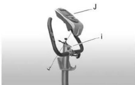
Close-up of a mechanical clamp or clip with a labeled component 'K' on a curved metal rod (no other text or symbols visible)To assemble the console, you must first connect the top cable and the cable for the hand pulse sensors to the console cables. Then push the console downward onto the mounting plate (i) on the handlebar shaft. CAUTION: Do not pinch the cable! Then, fasten the console using the screws. Do not tighten the screws too much. If you wish, you may insert the book holder into the slot (J) on the console. Push the console cap upward beneath the console until it latches into place. Make sure that the latching pins (K) seat properly.
SEAT
natural_image
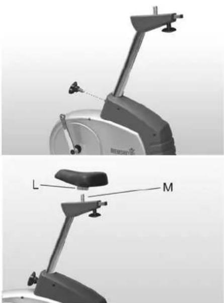
Technical illustration of a stationary exercise machine with labeled parts L and M (no text or symbols beyond labels)Insert the seat support. Insert the hand wheel for adjusting the seat and latch the pin of the hand wheel into a hole in the seat support. Then tighten the hand wheel. To attach the seat to the seat support, push the previously assembled clamp (L, beneath the seat) onto the mounting tube (M) on the seat holder. Align the seat and screw it tight in the desired position using the clamping screw. You can now set the horizontal distance between the handlebars and the seat using the hand wheel for setting the seat depth.
PEDALS
natural_image
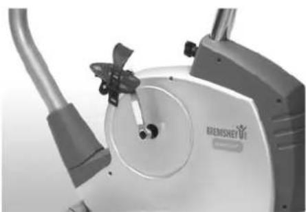
Close-up of a white exercise machine with attached lever and control knob (no visible text or symbols)Screw the pedals into the crank arms. Screw the left pedal (marked L for left-hand thread) into the left crank arm. Use the wrench and rotate it counterclockwise. Then screw the right pedal (marked R for right-hand thread) tightly clockwise into the right crank arm. Now attach the pedal straps to the pedals and adjust as desired.
TRANSFORMER
natural_image
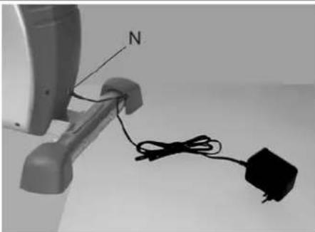
Close-up of a cable being inserted into a device with a labeled 'N' and a secondary plug (no text or symbols beyond labels)Insert the small connector into the receptacle (N) on the unit housing. Then connect the transformer to a 230 volt power outlet. The unit is now ready to use.
Before connecting the equipment to a power source, make sure that local voltage matches that indicated on the type plate: the equipment operates at either 230 V or 115 V (North American version). NOTE! The equipment must be connected to a grounded wall socket. Do not use extension wires when connecting the equipment to the power source. Make sure the power cord does not run underneath the equipment.
DANGER: Always switch off the power and unplug this appliance from the electrical outlet immediately after using.
WARNING: To reduce the risk of burns, fire, electric shock, or injury to persons:
1) An appliance should never be left unattended when plugged in. Unplug from outlet when not in use, and before carrying out any maintenance or repair procedures.
2) Do not operate under blanket or other combustive material. Excessive heating can occur and cause fire, electric shock, or injury to persons.
SAFETY NOTICE FOR UNITS WITH ELECTRIC POWER
- Do not use your home exercise unit if there is any sort of damage to the power cord or to the unit.
- Keep the power cord away from hot objects.
- Do not use your exercise unit out of doors or in damp locations.
- Do not route the power cord beneath a carpet and do not place any objects on the cord.
- Disconnect the plug from the power outlet before you move the unit, perform any needed maintenance or open the housing.
- Do not alter (for example, lengthen) the cord between the transformer and the unit.
EXERCISING
If the product is not stable, adjust the stabilizing screws under the rear support appropriately.
EXERCISE LEVEL
Working out using an exercise cycle is excellent aerobic exercise, the principle being that the exercise should be suitably light, but of long duration. Aerobic exercise is based on improving the body's maximum oxygen uptake, which in turn improves endurance and fitness. The ability of the body to burn fat as a fuel is directly dependent on its oxygen uptake capacity. Aerobic exercise should above all be pleasant. You should perspire, but you should not get out of breath during the workout. You must, for example, be able to speak and not just pant while pedaling. You should exercise at least three times a week, 30 minutes at a time, to reach a basic fitness level. Maintaining this level requires a few exercise sessions each week. Once the basic condition has been reached, it is easily improved, simply by increasing the number of exercise sessions. Exercise is always rewarding for weight loss, because it is the only way of increasing the energy spent by the body. This is why it is always worthwhile to combine regular exercise with a healthy diet. A dieter should exercise daily - at first 30 minutes or less at a time, gradually increasing the daily workout time to one hour.
You should start slowly at a low pedaling speed and low resistance, because strenuous exercise may subject the heart and circulatory system to excessive strain. As fitness improves, resistance and pedaling speed can be increased gradually. Exercise efficiency can be measured by monitoring the pulse. The pulse meter helps you monitor your pulse easily
during exercise, and thus to ensure that the exercise is sufficiently effective but not overstrenuous.
HEART RATE
No matter what your goal, you'll get the best results by training at the right level of effort, and the best measure is your own heart rate.
First find your maximum heart rate i.e. where the rate doesn't increase with added effort. C2's meter calculates your approximate maximum pulse level using the following formula:
220 - AGE
The maximum varies from person to person. The maximum heart-rate diminishes on average by one point per year. If you belong to a risk group, ask a doctor to measure your maximum heart rate for you.
We have defined three different heart-rate zones to help you with targeted training.
BEGINNER ● 50-60 % of maximum heart-rate.
Also suitable for weight-watchers, convalescents and those who haven't exercised for a long time. Three sessions a week of at least a half-hour each is recommended. Regular exercise considerably improves beginners' respiratory and circulatory performance and you will quickly feel your improvement.
TRAINER ● 60-70 % of maximum heart-rate.
Perfect for improving and maintaining fitness. Even reasonable effort develops the heart and lungs effectively, training for a minimum of 30 minutes at least three times a week. To improve your condition still further, increase either frequency or effort, but not both at the same time!
ACTIVE TRAINER ● 70-80 % of maximum heart-rate.
Exercise at this level suits only the fittest and presupposes long-endurance workouts.
● The heart rate is measured in three ways:
A) Using the handgrip heart rate sensors
B) Using an ear clip with cable (available as an optional extra)
c) Using a chest strap (wireless, telemetric), optional
The chest strap and receiver/adapter are available as optional extras.
Do not use more than one measuring system at the same time.
MEASURING PULSE WITH HAND SENSORS
C2 measures pulse with sensors which are located in the hand supports and which measure the pulse each time the user touches both sensors simultaneously.
For reliable pulse measurement, the skin must be in continuous contact with the sensors and the skin in contact with the sensors should be slightly moist. Too dry or too moist skin will impair hand pulse measurement. Please note also that active use of the upper body muscles during exercise may interfere with hand pulse measurement: active muscles transmit similar electronic signals as the heart muscle. Therefore, we recommend that arms be kept relaxed during pulse measurement.
EAR PULSE MEASUREMENT
- Fit the ear sensor wire plug into the connecting point of the meter.
- Attach the ear sensor to the earlobe.
If the sensor does not immediately start measuring your pulse or if the earlobe is cold, rub the earlobe with the fingers to speed up circulation. Physiological differences between different people may also cause disturbances in pulse measurement. In these cases, try measuring on the inside surface of the ear or on the tip of your finger. If measuring disturbances appear while training, test the functioning of the sensor while stationary. Strong, unintentional swaying while training may also disturb measurement. If pulse values rise above 150 beats/min., earlobe measurement may be affected by the speeding up of circulation. Sometimes a strong light source, e.g. a fluorescent tube, in the immediate vicinity of the user may cause disturbances in pulse measurement. In this case, test the functioning of the sensor by turning the ear sensor the other way round on the earlobe. Pulse reading can also be affected, if the battery power of the meter is too low. Clean the ear sensor after use with a damp cloth.
TELEMETRIC HEART RATE MEASUREMENT
This equipment has a built in pulse receiver, which is compatible with a telemetric Batavus Pro Check pulse transmitter.
NOTE! If you are fitted with a pacemaker, please consult a physician before using a wireless heart rate monitor.
If you want to measure your heart rate this way during your workout, moisten the grooved electrodes on the transmitter belt with water. Fasten the transmitter just below the chest with the elastic belt, firmly enough so that the electrodes remain in contact with the skin while training, but
not so tight that normal breathing is prevented. If you wear the transmitter and belt over a light shirt, moisten the shirt slightly at the points where the electrodes touch the shirt. The transmitter automatically transmits the heart-rate reading to the meter up to a distance of about 1 meter. The heart-rate value is displayed in the meter. Follow your heart rate during the training.
REMARKS ON TELEMETRIC MEASUREMENT
If the electrode surfaces are not moist, the heart rate reading will not appear on the display. If the electrodes are dry, they must be moistened again. Allow the electrodes to warm up properly to ensure accurate heart-rate measurement. If there are several telemetric heart rate measurement equipments next to each other, the distance between them should be at least 1,5 m. Similarly, if there is only one receiver and several transmitters in use, only one person with a transmitter should be within transmission range. The transmitter is switched to an active state only when it is being used for measurement. Sweat and other moisture can, however, keep the transmitter in an active state and waste battery energy. Therefore it is important to dry the electrodes carefully after use. When selecting training attire, please note that some fibers used in clothes (e.g. polyester, polyamide) create static electricity, which may prevent reliable heart rate measurement.
Please note that a mobile phone, television and other electrical appliances form an electro-magnetic field around them, which will cause problems in heart rate measurement.
CONSOLE
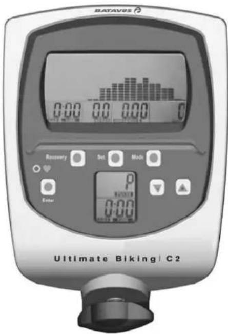
text_image
BAYAVUS 0:00 0.0 0.00 0 Recovery Det Mod Enter Ultimate Biking | C2BUTTONS
1. ENTER
Selects control panel functions and resets the training data to zero
2. SET
Sets values
3. +/-
Adjusts the training intensity (Level), training values and profile selection
4. SELECT
Confirms set values
5. RECOVERY
After finishing your training session, press this button to start recovery pulse measurement
FUNCTIONS
1. CALENDAR, TIME OF DAY AND ROOM TEMPERATURE
If you are not training and you have not pressed a button, the control panel switches into the Sleep mode after about four minutes. The time of day, date, day of the week and room temperature are shown on the display.
2. DISPLAY CHANGE (SCAN)
The display changes every 6 seconds:
- The main display A shows: Scan -- Speed -- Time -- Distance -- Calories -- Pulse
- While you are exercising, display B shows: RPM (revolutions), resistance (level) and the program profile.
3. TIME
The training time counts up, starting at 00:00, and runs to 99:59 minutes. Then the time begins again at 00:00. The colon (:) blinks once per second.
4. SPEED
The speed is displayed up to 99.9 km/h.
5. REVOLUTIONS
The crank arm revolutions are displayed in rpm (revolutions per minute).
6. DISTANCE
The distance is displayed in kilometers (km) and, if not preset, counts upward from 0.01 to 99.99.
If the distance is preset, this function counts down to 0.00 km. The total distance is added from all training sessions and shown on the display even if the current data have been erased using the Reset button. The total distance is only erased when the batteries are replaced.
7. CALORIES
Calories can be set to count up or down just like time or distance and are calculated during training. A maximum of 9999 calories are displayed per training session.
NOTE ON MEASURING CALORIES:
In this unit, energy consumption is calculated based on average values. Only the revolutions are used to calculate the values. However, because each person has different capabilities for producing energy (known as efficiency), the energy consumption displayed can, by necessity, only be an approximation of the actual consumption and cannot be used for therapeutic purposes. The energy consumption during a training session is displayed in kcal (kilocalories). To convert this into joules, use this formula: 1 kcal = 4.187 kJ.
8. PULSE RATE RANGES
While training using pulse rates, the control panel computes three pulse rate ranges in accordance with your maximum pulse rate based on your personal data.
When you begin your training session, the display switches from the preset pulse to the actual pulse rate. The \% number of the heart rate range in which you are currently training blinks next to the pulse rate.
Example: If you wish to train in the 75% range, but the currently displayed range is lower or higher, you must decrease or increase your performance appropriately so that your pulse decreases or increases. You achieve this by changing the resistance or the pedaling speed. To adjust the resistance, please use the +/- buttons on the control panel.
If you wish to train using values other than the preset values, ignore the \% numbers and concentrate only on your actual pulse rate.
NOTE: Before the control panel can display the pulse rate or the pulse ranges, it needs at least 10 seconds for calculation purposes.
9. INTENSITY (LEVEL)
The training intensity is shown on Display B as a bar diagram (levels 1 -- 8) during training.
10. PROGRAMS
The control panel contains the following:
• M: A manual program (8 levels)
● P: A program with profiles in levels (10 different profiles)
SWITCHING ON AND PROGRAMMING
When you switch on the control panel, the Calendar mode is displayed.
DATA ENTRY
If you do not wish to make any changes to, for example, the time or date, press the ENTER button until the training time of 00:00 appears on Display A.
At the same time, M for the manual program appears on Display B.
You can switch to the programming selection of P = program profiles using the + button.
A. TRAINING WITH THE MANUAL PROGRAM M
-
Press the SELECT button.
Display B then shows the intensity as a flat bar diagram and a number (1 -- 8). Alternately, the speed and intensity (1 -- 8) are displayed.
Without entering training data such as Time / Distance, you may now start training. Select the intensity levels using the +/-buttons.
For training using the manual program with preset data, select the range using the ENTER button. -
Set the values using the SET button (Figure 7). The values are always adjusted upward.
- Press the ENTER button until the time display is selected again. Select the time. Then start training.
B. TRAINING USING PROGRAM PROFILES ("P")
- After changing from M to P, press the SELECT button. Using the +/- buttons, select the program 1 -- 10. Confirm using the SELECT button. The level profile is shown on Display B.
- You can now increase the base intensity (Level) using the +/- buttons. If desired, use the ENTER button to switch to training value entry mode. If you do not wish to enter values, you may begin training immediately.
SETTING THE TIME OF DAY TIME AND CALENDAR
After plugging the unit in, or by pedaling and pressing the ENTER button, you can set these values. The year 2005 will blink.
- Set the year using the SET button.
- Confirm by pressing the ENTER button. The number for the month M will blink.
- Set the month using the SET button.
- Press the ENTER button. The time of day (hours) D will blink.
- Set the time using the SET button.
- Press the ENTER button. The minutes will blink.
- Set using the SET button.
- Press the ENTER button. You can now enter the training data.
ADDITIONAL NOTES:
- Quick start
With the transformer connected, start pedaling to switch the control panel from the Sleep mode into the input mode. - You can enter values on Display A when one of the bars is displayed on the left edge.
- Adjustment (Target Setting) is only possible if the Park symbol P is visible on Display A.
- The resistance (Level) can be adjusted using the +/- buttons during training.
- If you have set several functions to count down, a signal sounds when the first function reaches zero. Press the + button to switch the sound off. If you continue training, the function automatically begins counting upward from zero.
TRANSPORT AND STORAGE
Please follow these instructions when carrying and moving the equipment about, because lifting it incorrectly may strain your back or risk other accidents:
The device is easy to move by pushing along on the integrated transport wheels. Tilt the device from the front and push along the floor on the wheels at the front support. We recommend that you use a protective base when transporting the equipment.
To prevent the equipment malfunctioning, store in a dry place with as little temperature variation as possible and protected from dust.
MAINTENANCE
The equipment requires very little maintenance. Check, however, from time-to-time that all screws and nuts are tight.
- After exercising, clean the equipment with a soft, absorbent cloth. Do not use solvents. Sweat may cause corrosion: we recommend therefore that you protect all metal surfaces outside the plastic covers with teflon.
- Never remove the equipment's protective casing.
MALFUNCTIONS
NOTE! Despite continuous quality control, defects and malfunctions caused by individual components may occur in the equipment. In most cases it's unnecessary to take the whole device in for repair, as it's usually sufficient to replace the defective part. Always give the model, serial number of your equipment and in case of malfunctions also conditions of use, nature of malfunction and any error code.
When you encounter unusual behavior from the device, contact your local Batavus dealer for service.
If you require spare parts, always give the model, serial number of your equipment and the spare part number for the part you need. The spare part list is at the back of this manual. Use only spare parts mentioned in the spare part list.
TECHNICAL SPECIFICATIONS
Length.... 102 cm
Width 55 cm
Height....146 cm
Weight....37 kg
The C2 meets the requirements of the EU's
EMC Directives on electromagnetic compatibility (89/336/EEC). This product therefore carries the CE label.
The C2 meets EN precision and safety standards (EN-957).
Due to our continuous policy of product development, Batavus reserves the right to change specifications without notice.
NOTE! The instructions must be followed carefully in the assembly, use and maintenance of your equipment. The warranty does not cover damage due to negligence of the assembly, adjustment and maintenance instructions described herein. Changes or modifications not expressly approved by Batavus will void the user's authority to operate the equipment!
We wish you many enjoyable trainings!
INHALT
MONTAGE 12
BENUTZUNG 14
TRAINIEREN MIT Batavus 14
HERZFREQUENZ 15
COCKPIT 16
natural_image
Close-up of a stationary exercise machine with adjustable arm and sensor (no visible text or symbols)natural_image
Close-up of a stationary exercise machine with visible legs and feet, no text or symbols presentnatural_image
Close-up of a metallic mechanical component with a curved handle and black base (no text or symbols visible)natural_image
Close-up of a robotic arm with a metallic tool inserted, showing mechanical components and motion (no text or symbols visible)natural_image
Close-up of a mechanical device with a curved pipe and attached lever, showing a small component (no text or symbols visible)natural_image
Close-up of a black curved cable with a labeled force 'F' and a small cable, no text or symbols present.
text_image
H E Gnatural_image
Exterior view of a modern stationary exercise machine (no visible text or symbols)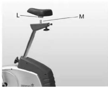
text_image
L Mnatural_image
Close-up of a white electric bike with attached lever and cable (no visible text or symbols)natural_image
Close-up of a cable being inserted into a device with a labeled 'N' and a secondary plug (no text or symbols beyond labels)natural_image
Close-up of a medical or laboratory device with a rod and lever mechanism (no visible text or symbols)natural_image
Close-up of a mechanical exercise machine with visible legs, arms, and a screw (no text or symbols)natural_image
3D rendered image of a metallic tool or connector with a handle and lever (no text or symbols visible)natural_image
Close-up of a mechanical tool or device with a metallic component and a spring-like extension (no visible text or symbols)natural_image
Close-up of a mechanical device with a curved pipe and attached lever (no visible text or symbols)natural_image
Close-up of a black cable with a labeled component 'F' and a small plug, no text or symbols present.
text_image
H E Gnatural_image
Two technical diagrams of a stationary exercise machine, showing front and side views with labeled parts (no text or symbols beyond labels)natural_image
Close-up of a BEKSHEY electric vehicle charging station with visible branding and mechanical components (no readable text or symbols)natural_image
Close-up of a cable being inserted into a device with a labeled 'N' and a secondary plug (no text or symbols on the device itself)A. EXERCICE AVEC LE PROGRAMME MANUEL "M"
natural_image
Close-up of a medical device with attached mechanical components (no visible text or symbols)natural_image
Close-up of a mechanical exercise device with visible legs, feet, and adjustment knobs (no text or symbols)natural_image
Close-up of a metallic mechanical device with a curved handle and black base (no visible text or symbols)natural_image
Close-up of a robotic arm with a tool inserted, showing mechanical components and a circular housing (no text or symbols visible)natural_image
Close-up of a mechanical device with a curved pipe and lever mechanism (no visible text or symbols)natural_image
Close-up of a black flexible hose with attached cable and connector, labeled 'F' (no text or symbols beyond label)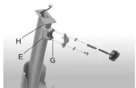
text_image
H E Gnatural_image
Close-up of a mechanical clamp or bracket with a labeled arrow pointing to the letter 'K' (no other text or symbols visible)natural_image
Two views of a stationary exercise machine with labeled parts (L and M), no text or symbols present.natural_image
Close-up of a Siemens air conditioner unit with attached tubing and control panel (no visible text or symbols)natural_image
Close-up of a cable being inserted into a device labeled 'N', with a separate black plug attached (no text or symbols visible)2. WEERGAVENWISSELING (SCAN)
Om de 6 seconden wisselt de weergave:
A. TRAINING MET HET MANUELE PROGRAMMA "M"
natural_image
Close-up of a medical or exercise equipment device with a screw and adjustment lever (no visible text or symbols)natural_image
Close-up of a mechanical device with visible joints and a screw, no text or symbols presentnatural_image
3D rendered image of a metallic tool or connector with a curved handle and black base (no text or symbols visible)natural_image
Close-up of a mechanical assembly with a tool interacting with a cylindrical component (no visible text or symbols)natural_image
Close-up of a mechanical device with a curved pipe and attached lever (no visible text or symbols)natural_image
Close-up of a black cable with a labeled component 'F' and a small connector (no text or symbols beyond the label)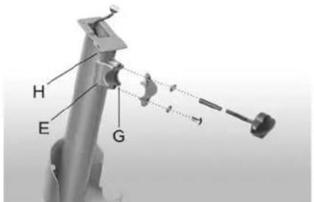
text_image
H E Gnatural_image
Mechanical diagram showing two views of a stationary exercise machine with labeled parts (no text or symbols present)natural_image
Close-up of a white electric vehicle (no visible text or symbols)natural_image
Close-up of a cable being inserted into a device with a black plug and labeled 'N' (no text or symbols beyond the label)SENSORI NEL MANUBRIO
natural_image
Close-up of a mechanical device with a lever and adjustment knob (no visible text or symbols)natural_image
Close-up of a white exercise machine foot with visible joints and adjustment knobs (no text or symbols)natural_image
3D rendered image of a mechanical tool or connector with a curved handle and black base (no text or symbols visible)natural_image
Close-up of a robotic arm with a metallic tool inserted, showing mechanical components and a circular housing (no text or symbols visible)natural_image
Close-up of a mechanical device with a curved handle and lever mechanism (no visible text or symbols)natural_image
Close-up of a black flexible hose with a cable and labeled component 'F' (no text or symbols beyond label)
text_image
H E Gnatural_image
Two technical diagrams of a stationary exercise machine, showing front and side views with labeled parts (no text or symbols present)natural_image
Close-up of a Siemens BEAMS machine with attached cable and adjustment knob (no visible text or symbols)natural_image
Close-up of a cable being inserted into a device with a labeled point 'N' (no text or symbols beyond the label)TRANSPORT OCH FÖRVARING ....63
UNDERHÅLL 63
STÖRNINGAR VID ANVÄNDNING 63
TEKNISKA DATA 63
BRUKSANVISNING
natural_image
Close-up of a medical or laboratory device with a metallic rod and attached lever (no visible text or symbols)natural_image
Close-up of a stationary exercise machine with visible legs, wheels, and a screw (no text or symbols)natural_image
3D rendered image of a mechanical device with a lever and clamped parts (no text or symbols visible)natural_image
Close-up of a robotic arm with a metallic tool and mechanical components (no visible text or symbols)natural_image
Close-up of a mechanical component with a curved pipe and attached lever (no visible text or symbols)natural_image
Close-up of a black flexible hose with attached cable and connector, labeled 'F' (no text or symbols beyond label)
text_image
H E Gnatural_image
Close-up of a mechanical clamp or bracket with a labeled arrow pointing to the letter 'K' (no other text or symbols visible)natural_image
Two views of a BEACHSOL stationary bike with labeled components (L and M), no text or symbols present.natural_image
Close-up of a BEMCHETY electric vehicle (no visible text or symbols on body)natural_image
Close-up of a cable being inserted into a device with a black plug, labeled 'N' (no text or symbols on the device itself)A. TRÄNING MED DET MANUELLA M- PROGRAMMET
natural_image
Close-up of a medical or rehabilitation device with a metallic tool and screw base (no visible text or symbols)natural_image
Close-up of a stationary exercise machine with visible legs, feet, and screw base (no text or symbols)natural_image
Close-up of a metallic mechanical component with a curved handle and black base (no text or symbols visible)natural_image
Close-up of a mechanical device with a lever and adjustment knob (no visible text or symbols)natural_image
Mechanical assembly diagram showing a lever mechanism with a curved handle and shaft (no text or symbols)natural_image
Close-up of a black cable with a labeled component 'F' and a connector, no readable text or symbols beyond the label.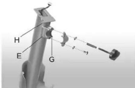
text_image
H E Gnatural_image
Close-up of a mechanical clamp or bracket with a labeled component 'K' pointing to it (no other text or symbols visible)natural_image
Close-up of a stationary exercise machine with adjustable arm and head (no visible text or symbols)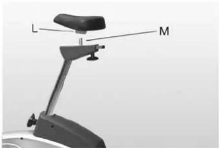
natural_image
Mechanical device with labeled parts L and M, no visible text or symbols beyond labelsnatural_image
Close-up of a white BEEMSHEY electric shaver with attached cable and valve (no visible text or symbols)natural_image
Close-up of a cable being inserted into a device with a compass needle labeled 'N' (no text or symbols on the device itself)text_image
Technical diagram of a mechanical assembly with numbered components and labeled parts
BATAVUS
Austria
DoWi GmbH
Ziehrerstrasse 80
8041 Graz
Tel. +43 316 71 64 12
Fax +43 316 71 64 35
www.dowi.at
Benelux
Batavus B.V.
Postbus 60001
1320 AA Almere
Nederland
Tel. +31 36 546 00 50
Fax +31 36 546 00 55
www.Batavus.nl
Finland
Batavus Oy Ltd
PL 750
20361 Turku
Tel. +358 2 513 31
Fax +358 2 513 3323
Germany
Batavus GmbH
Heidenfelder Str. 5
97525 Schwebheim
Tel. +49 9723 9345 0
Fax +49 9723 9345 19
www.Batavus.de
Great Brital
Bolton Stirland International Ltd.
Boland House
Nottingham South
Industrial Lane
Wilford
Tel. +44 115 98 22844
Fax +44 115 98 17784
www.bsfitness.co.uk
USA / Canada
Accell Fitness North America Inc.
130 Hayward Ave, Suite 2
N2C 2E4
Kitchener, ON Canada
Tel. 1-888-388-6887
Fax: 1-519-576-2521
www.accellfitness.com