C1 - Exercise bike Batavus - Free user manual and instructions
Find the device manual for free C1 Batavus in PDF.
Frequently Asked Questions - C1 Batavus
User questions about C1 Batavus
0 question about this device. Answer the ones you know or ask your own.
Ask a new question about this device
Download the instructions for your Exercise bike in PDF format for free! Find your manual C1 - Batavus and take your electronic device back in hand. On this page are published all the documents necessary for the use of your device. C1 by Batavus.
USER MANUAL C1 Batavus
OWNER'S MANUAL P. 2-8
IMPORTANT SAFETY INSTRUCTIONS
Read this guide through carefully before assembling, using or servicing your fitness equipment. Please keep the guide somewhere safe; it will provide you now and in the future with the information you need to use and maintain your equipment. Always follow these instructions with care. Please note that the warranty does not cover damage due to shipping or negligence of adjustment or maintenance instructions described in this manual.
NOTE ABOUT YOUR HEALTH
- Before you start any training, consult a physician to check your state of health.
- If you experience nausea, dizziness or other abnormal symptoms while exercising, stop your workout at once and consult a physician.
- To avoid muscular pain and strain, begin each workout by warming up and end it by cooling down (slow pedaling at low resistance). Don't forget to stretch at the end of the workout.
NOTE ABOUT THE EXERCISING ENVIRONMENT
- The equipment is not to be used outdoors.
- Place the equipment on a firm, level surface. Place the equipment on a
protective base to avoid any damages to the floor beneath the equipment.
- Make sure that the exercising environment has adequate ventilation. To avoid catching cold, do not exercise in a draughty place.
- In training, the equipment tolerates an environment measuring +10°C to +35°C. The equipment can be stored in temperatures ranging between -15°C and +40°C. Air humidity in the training or storage environment must never exceed 90%.
NOTE ABOUT USING THE EQUIPMENT
- If children are allowed to use the equipment, they should be supervised and taught to use the equipment properly, keeping in mind the child's physical and mental development and their personality. Also make sure that pet animals keep a safe distance to the product when it is transporting or used for training.
- Before you start using the equipment, make sure that it functions correctly in every way. Do not use a faulty equipment.
- Press the keys with the tip of the finger; your nails may damage the key membrane.
- Never lean on the meter.
- Never remove the side covers. Do not step on the frame casing.
- Only one person may use the equipment at a time.
- Wear appropriate clothing and shoes when exercising.
- Protect the meter from sunlight and always dry the surface of the meter if there are any drops of sweat on it.
- The equipment must not be used by persons weighing over 135 kg.
- The equipment has been designed for home use. The Batavus warranty applies only to faults and malfunctions in home
use (24 months). Further information on warranty terms can be obtained from your national Batavus distributor. Please note that the warranty terms may vary from one country to another.
- Do not attempt any servicing or adjustments other than those described in this guide. Everything else must be left to someone familiar with the maintenance of electromechanical equipments and authorised under the laws of the country in question to carry out maintenance and repair work.
SAVE THIS INSTRUCTION MANUAL
ASSEMBLY
Start by unpacking the equipment. Two people are needed for the assembly.
Assembly kit (contents marked with * in the spare part list): keep the assembly tools, as you may need them e.g. for adjusting the equipment
If necessary, please contact your dealer with the model, equipment serial no. and spare part no. of the missing part. You'll find a spare part list at the back of this guide. The packaging includes a silicate bag for absorbing moisture during storage and transportation. Please dispose of the bag once you have unpacked the equipment. The directions left, right, front and back are defined as seen from the exercising position. Allow at least 100 cm of clearance around the equipment. We also recommend opening the package and assembling the product on a protective base.
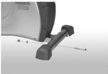
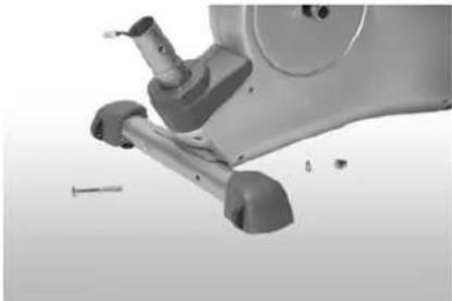
REAR AND FRONT SUPPORT
natural_image
Close-up of a medical or surgical device with a metallic tool and alignment pins (no visible text or symbols)Mount the rear foot tube to the base frame using the screws, the washers and the cap nuts.
natural_image
Close-up of a mechanical device with visible joints and a screw, no text or symbols presentMount the front foot tube to the base frame in the same way. Make sure that the rollers for the foot caps face forward and down during assembly
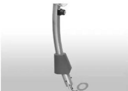
FRONT TUBE
natural_image
Close-up of a metallic cylindrical device with a circular end cap and connector (no visible text or symbols)Push the tube cover from below onto the handlebar shaft. Push the foam ring for the tube cover onto the handlebar shaft and push upward.
natural_image
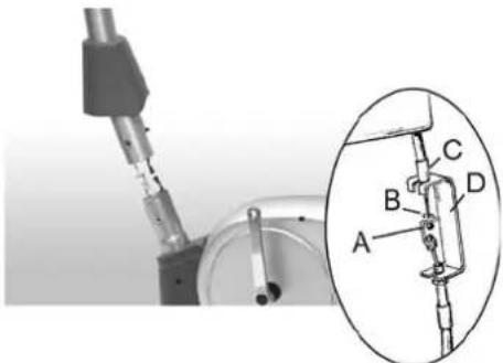
Mechanical assembly diagram showing a shaft and housing with labeled parts A, B, C, D (no text or symbols beyond labels)To mount the adjustment unit, adjust the brake wire to position 1 so that the ball (A) protrudes as far as possible from the end piece (C). Connect the wire coming from the top to the wire coming out of the frame. To do this, first hook the ball (A) into the wire eyelet (B) and then latch the end piece (C) into the holder (D). Connect the cable connectors to each other.
natural_image
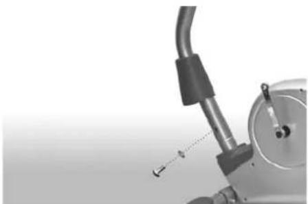
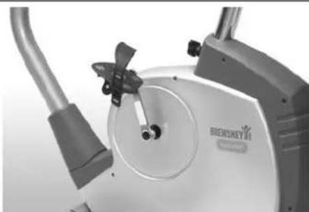
Close-up of a mechanical device with a curved pipe and attached lever, showing a small tool or component (no visible text or symbols)Place the handlebar shaft onto the frame tube on the base frame and fasten it using the screws and the washers. CAUTION: Do not pinch the cable! Push the tube cover together with the housing foam ring downward onto the housing.
HANDLEBAR
natural_image
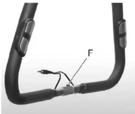
Close-up of a black flexible hose with a cable and labeled component 'F' (no text or symbols beyond label)
text_image
J H E GAssemble the handlebars using the handlebar clamp, the screw, the washers, the spacer sleeve and the hand wheel for adjusting the handlebars. Place the handlebar tube into the holding fixture (E) on the handlebar shaft. CAUTION: The pin (F) must be inserted into the groove (G)! Push the handlebar clamp over the handlebar tube and loosely insert the screw with the washer. The handlebar clamp should wrap around the tube uniformly. Insert the hand wheel for adjusting the handlebars together with the washer and the spacer sleeve into the upper hole and tighten. Push the cable from the hand pulse sensors through the opening (H) beneath the mounting plate (J) and thread it upward out of the handlebar shaft.
CONSOLE
natural_image
Close-up of a mechanical device with lever and handle (no visible text or symbols)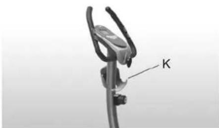
natural_image
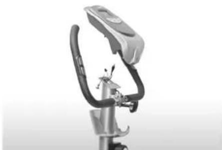
Close-up of a mechanical device with a labeled component 'K' (no other text or symbols visible)Insert the batteries on the back side of the console. Connect the cable connectors coming out of the handlebar shaft to the console and place the console from above onto the mounting plate on the handlebar shaft. CAUTION: Do not pinch the cable! Fasten the console using the screws. Do not tighten the screws too much. Push the console cap upward and latch it in the console bottom section. Make sure that the latching pins (K) seat properly.
SEAT
natural_image
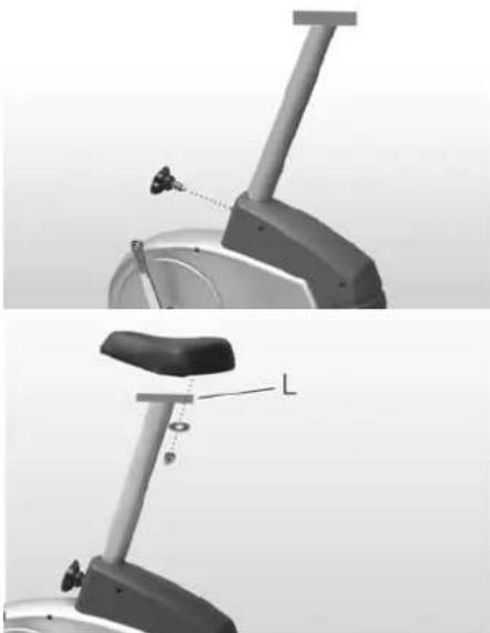
Mechanical diagram showing two views of a stationary exercise bike with labeled components (no text or symbols present)Insert the seat support. Screw in the hand wheel for adjusting the seat and latch the pin of the hand wheel into a hole in the seat support. Tighten the hand wheel. Fasten the seat to the triangular mounting plate (L) of the seat support using the nuts and the washers.
PEDALS
natural_image
Close-up of a Siemens BEMSKY electric vehicle (no visible text or symbols on body)Screw the pedals into the threads of the crank arms. Screw the left pedal (marked L for left-hand thread) into the left crank arms. Use the wrench and rotate it counterclockwise. Screw the right pedal (marked R for right-hand thread) tightly clockwise into the right crank arm. Now attach the pedal straps to the pedals.
EXERCISING
If the product is not stable, adjust the stabilizing screws under the rear support appropriately.
EXERCISE LEVEL
Working out using an exercise cycle is excellent aerobic exercise, the principle being that the exercise should be suitably light, but of long duration. Aerobic exercise is based on improving the body's maximum oxygen uptake, which in turn improves endurance and fitness. The ability of the body to burn fat as a fuel is directly dependent on its oxygen uptake capacity. Aerobic exercise should above all be pleasant. You should perspire, but you should not get out of breath during the workout. You must, for example, be able to speak and not just pant while pedaling. You should exercise at least three times a week, 30 minutes at a time, to reach a basic fitness level. Maintaining this level requires a few exercise sessions each week. Once the basic condition has been reached, it is easily improved, simply by increasing the number of exercise sessions. Exercise is always rewarding for weight loss, because it is the only way of increasing the energy spent by the body. This is why it is always worthwhile to combine regular exercise with a healthy diet. A dieter should exercise daily - at first 30 minutes or less at a time, gradually increasing the daily workout time to one hour.
You should start slowly at a low pedaling speed and low resistance, because strenuous exercise may subject the heart and circulatory system to excessive strain. As fitness improves, resistance and pedaling speed can be increased gradually. Exercise efficiency can be measured by monitoring the pulse. The pulse meter helps you monitor your pulse easily during exercise, and thus to ensure that the exercise is sufficiently effective but not overstrenuous.
HEART RATE
No matter what your goal, you'll get the best results by training at the right level of effort, and the best measure is your own heart rate.
First find your maximum heart rate i.e. where the rate doesn't increase with added effort. C1's meter calculates your approximate maximum pulse level using the following formula:
220 - AGE
The maximum varies from person to person. The maximum heart-rate diminishes on average by one point per year. If you belong to a risk group, ask a doctor to measure your maximum heart rate for you.
We have defined three different heart-rate zones to help you with targeted training.
BEGINNER ● 50-60 % of maximum heart-rate.
Also suitable for weight-watchers, convalescents and those who haven't exercised for a long time. Three sessions a week of at least a half-hour each is recommended. Regular exercise considerably improves beginners' respiratory and circulatory performance and you will quickly feel your improvement.
TRAINER ● 60-70 % of maximum heart-rate.
Perfect for improving and maintaining fitness. Even reasonable effort develops the heart and lungs effectively, training for a minimum of 30 minutes at least three times a week. To improve your condition still further, increase either frequency or effort, but not both at the same time!
ACTIVE TRAINER ● 70-80 % of maximum heart-rate.
Exercise at this level suits only the fittest and presupposes long-endurance workouts.
- The heart rate is measured in three ways:
A) Using the handgrip heart rate sensors
B) Using an ear clip with cable (available as an optional extra)
c) Using a chest strap (wireless, telemetric), optional
The chest strap and receiver/adapter are available as optional extras.
Do not use more than one measuring system at the same time.
MEASURING PULSE WITH HAND SENSORS
C1 measures pulse with sensors which are located in the hand supports and which measure the pulse each time the user touches both sensors simultaneously.
For reliable pulse measurement, the skin must be in continuous contact with the sensors and the skin in contact with the sensors should be slightly moist. Too dry or too moist skin will impair hand pulse measurement. Please note also that active use of the upper body muscles during exercise may
interfere with hand pulse measurement: active muscles transmit similar electronic signals as the heart muscle. Therefore, we recommend that arms be kept relaxed during pulse measurement.
EAR PULSE MEASUREMENT
- C1 the ear sensor wire plug into the connecting point of the meter.
- Attach the ear sensor to the earlobe.
If the sensor does not immediately start measuring your pulse or if the earlobe is cold, rub the earlobe with the fingers to speed up circulation. Physiological differences between different people may also cause disturbances in pulse measurement. In these cases, try measuring on the inside surface of the ear or on the tip of your finger. If measuring disturbances appear while training, test the functioning of the sensor while stationary. Strong, unintentional swaying while training may also disturb measurement. If pulse values rise above 150 beats/min., earlobe measurement may be affected by the speeding up of circulation. Sometimes a strong light source, e.g. a fluorescent tube, in the immediate vicinity of the user may cause disturbances in pulse measurement. In this case, test the functioning of the sensor by turning the ear sensor the other way round on the earlobe. Pulse reading can also be affected, if the battery power of the meter is too low. Clean the ear sensor after use with a damp cloth.
TELEMETRIC HEART RATE MEASUREMENT
This equipment can be equipped with a pulse receiver, which is compatible with a telemetric Batavus Pro Check pulse transmitter.
NOTE! If you are fitted with a pacemaker, please consult a physician before using a wireless heart rate monitor.
If you want to measure your heart rate this way during your workout, moisten the grooved electrodes on the transmitter belt with water. Fasten the transmitter just below the chest with the elastic belt, firmly enough so that the electrodes remain in contact with the skin while training, but not so tight that normal breathing is prevented. If you wear the transmitter and belt over a light shirt, moisten the shirt slightly at the points where the electrodes touch the shirt. The transmitter automatically transmits the heart-rate reading to the meter up to a distance of about 1 meter. The heart-rate value is displayed in the meter. Follow your heart rate during the training.
REMARKS ON TELEMETRIC MEASUREMENT
If the electrode surfaces are not moist, the heart rate reading will not appear on the display. If the electrodes are dry, they must be moistened again. Allow the electrodes to warm up properly to ensure accurate heart-rate measurement. If there are several telemetric heart rate measurement equipments next to each other, the distance between them should be at least 1,5 m. Similarly, if there is only one receiver and several transmitters in use, only one person with a transmitter should be within transmission range. The transmitter is switched to an active state only when it is being used for measurement. Sweat and other moisture can, however, keep the transmitter in an active state and waste battery energy. Therefore it is important to dry the electrodes carefully after use. When selecting training attire, please note that some fibers used in clothes (e.g. polyester, polyamide) create static electricity, which may prevent reliable heart rate measurement.
Please note that a mobile phone, television and other electrical appliances form an electro-magnetic field around them, which will cause problems in heart rate measurement.
CONSOLE
text_image
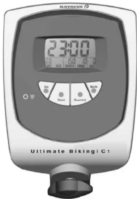
BAYAVUS 2:30:00 0.0 15.0 10.0 Set Reset Recovery Mode Ultimate Biking | C1BUTTONS
1. ENTER
Press Enter to select console functions. When you have finished an entry, press Enter to confirm your entry and move to the next function.
2. + -
These buttons are used to set values for the Time, Distance, Calories and Pulse functions. The console must be in the Stop function. If you are not training, the symbol P automatically appears
at the top left of the display. Values are always set from zero upwards in increments of 1. If you press and hold the button, the value changes rapidly. If the set value is too high, press the Reset button briefly to reset the value to zero again.
3. RESET
Press this button briefly to reset the values for the current function. Pressing and holding the button will reset values for all functions. Only the total distance will be saved.
4. RECOVERY
When you have finished training, press this button to begin recovery pulse measurement.
FUNCTIONS
1. SPEED
The rotations of the crank arm are shown on the display. The display changes between the rotations per minute (rpm) and the speed (km/h) every 6 seconds.
The speed is displayed up to 99.9 km/h.
2. TIME
The training time counts upward, starting at 00:00, and runs to 99:99 minutes. Then the time begins again at 00:00. The colon (:) blinks once per second.
3. DISTANCE
The distance is displayed in kilometers (km) and, if not preset, counts upward from 0.00 to 99.99 in increments of 0.01 kilometers.
If the distance is preset, this function counts down to 0.00 km. The total distance is added from all training sessions and shown on the display if the current data have not been erased using the Reset button. The total distance is only erased when the batteries are replaced.
4. CALORIES
Calories can be set to count up or down just like time or distance and are calculated during training. A maximum of 9999 calories are displayed per training session.
NOTES ON MEASURING CALORIES:
In this unit, energy consumption is calculated based on average values. Only the revolutions are used to calculate the values. However, as each person has different capabilities for producing energy (known as efficiency), the energy consumption displayed can, by necessity, only be an approximation of the actual consumption and cannot be used for therapeutic purposes. The energy consumption during a training session is displayed in kcal (kilocalories). To convert this into joules, use this formula: 1 kcal = 4.187 kJ.
5. PULSE PROGRAM
Values are set just like before for time and distance.
Before the console can display the pulse rate or the pulse ranges, it needs at least 10 seconds for calculation purposes.
The automatic display changing function switches off when you press the Enter button to enter values. When you start training, the SCAN function is activated again. Then, one of the functions is shown in the top field of the display using large numbers, alternating every 6 seconds.
The room temperature is automatically shown on the display in the Sleep mode.
INPUT SEQUENCE
When training with preset values or with the pulse rate ranges, the sequence is as follows:
The SCAN function must not be active. The symbol P appears on the display. Use the Enter button to select the Time function. If you leave the setting at 00:00, the time will count up during training. If you select a time using the Set button, the time will count down. Confirm the entry using the Enter button. The console will switch to the next function. The input sequence here is just like what you did for the time. Confirm the entries using the Enter button and start training.
GENERAL INFORMATION:
You cannot operate the unit until you insert the batteries into the console.
If you have set several functions to count down, a signal sounds when the first function reaches zero. If you continue training, the function automatically begins counting upward from zero. If there is no input or you are not training, the console automatically switches to the Sleep mode after four minutes.
RECOVERY PULSE MEASUREMENT
Measure your recovery pulse after training. The measurement can only be started if the pulse measurement is activated and the pulse value is shown on the display.
Start the recovery pulse measurement by 1.
pressing RECOVERY.
- The measurement takes 60 seconds.
- After the measurement is finished, the display shows the result F1-F6 (F1 = best result). Please note that your results are in a relation to the pulse level in the beginning of the measurement, and that your results are personal and cannot directly be compared with any other person's results. In order to improve the reliability of recovery pulse measurement, always try to standardize the measurement situation as accurately as possible; start measuring at the same heart rate level as precisely as possible.
- To switch back to the main display by pressing RECOVERY.
TRANSPORT AND STORAGE
Please follow these instructions when carrying and moving the equipment about, because lifting it incorrectly may strain your back or risk other accidents:
The device is easy to move by pushing along on the integrated transport wheels. Tilt the device from the front and push along the floor on the wheels at the front support. We recommend that you use a protective base when transporting the equipment.
To prevent the equipment malfunctioning, store in a dry place with as little temperature variation as possible and protected from dust.
MAINTENANCE
The equipment requires very little maintenance. Check, however, from time-to-time that all screws and nuts are tight.
- After exercising, clean the equipment with a soft, absorbent cloth. Do not use solvents. Sweat may cause corrosion: we recommend therefore that you protect all metal surfaces outside the plastic covers with teflon.
- Never remove the equipment's protective casing.
MALFUNCTIONS
NOTE! Despite continuous quality control, defects and malfunctions caused by individual components may occur in the equipment. In most cases it's unnecessary to take the whole device in for repair, as it's usually sufficient to replace the defective part. Always give the model, serial number of your equipment and in case of malfunctions also conditions of use, nature of malfunction and any error code.
When you encounter unusual behavior from
the device, contact your local Batavus dealer for service.
If you require spare parts, always give the model, serial number of your equipment and the spare part number for the part you need. The spare part list is at the back of this manual. Use only spare parts mentioned in the spare part list.
TECHNICAL SPECIFICATIONS
Length....98 cm Width....55 cm Height....146 cm Weight....32 kg
The C1 meets the requirements of the EU's EMC Directives on electromagnetic compatibility (89/336/EEC). This product therefore carries the CE label.
The C1 meets EN precision and safety standards (EN-957).
Due to our continuous policy of product development, Batavus reserves the right to change specifications without notice.
NOTE! The instructions must be followed carefully in the assembly, use and maintenance of your equipment. The warranty does not cover damage due to negligence of the assembly, adjustment and maintenance instructions described herein. Changes or modifications not expressly approved by Batavus will void the user's authority to operate the equipment!
We wish you many enjoyable trainings!
INHALT
MONTAGE 10
BENUTZUNG 12
TRAINIEREN MIT Batavus 12
HERZFREQUENZ 13
COCKPIT 14
natural_image
Mechanical device with attached lever and screw base (no visible text or symbols)natural_image
Close-up of a mechanical device with visible joints and a screw, no text or symbols presentnatural_image
Close-up of a metallic cylindrical device with a circular base and connector (no visible text or symbols)natural_image
Mechanical assembly diagram showing a shaft and lever with labeled parts A, B, C, D (no text or symbols present)natural_image
Close-up of a mechanical device with a curved handle and attached lever, showing alignment lines (no text or symbols visible)natural_image
Close-up of a black flexible hose with attached cable and connector (no text or symbols visible)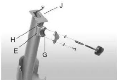
text_image
J H E Gnatural_image
Two-panel image showing a mechanical device with a clamp and labeled component 'K' (no text or symbols on the device itself)natural_image
Two technical diagrams of a stationary exercise bike, showing front and side views with no text or symbols.natural_image
Close-up of a BEKSNEY electric exercise machine (no visible text or symbols on body)natural_image
Close-up of a medical or fitness device with adjustable arm and shaft (no visible text or symbols)natural_image
Close-up of a mechanical exercise machine with visible legs and joints (no text or symbols)natural_image
Close-up of a metallic cylindrical device with a circular base and attached sensor (no visible text or symbols)natural_image
Mechanical assembly diagram showing a shaft and lever with labeled parts A, B, C, D (no text or symbols beyond labels)natural_image
Close-up of a mechanical device with a curved pipe and attached lever, showing a dimension line (no text or symbols)text_image
F J H E Gnatural_image
Two-panel image showing a mechanical device with a clamp and labeled component 'K' (no text or symbols on the devices themselves)natural_image
Two technical diagrams of a stationary exercise machine, showing front and side views with no visible text or symbols.natural_image
Close-up of a DHMCHET exercise machine with attached cable and lever (no visible text or symbols)natural_image
Close-up of a medical or rehabilitation device with a metallic tool and screwdriver (no visible text or symbols)natural_image
Close-up of a mechanical exercise machine with visible legs, wheels, and a screw (no text or symbols)natural_image
Close-up of a metallic cylindrical device with a small circular component attached (no visible text or symbols)natural_image
Mechanical assembly diagram showing a lever mechanism with labeled parts A, B, C, D (no text or symbols beyond labels)natural_image
Close-up of a mechanical device with a curved pipe and attached lever, showing a small scale indicator (no text or symbols visible)natural_image
Close-up of a mechanical device with lever and handle (no visible text or symbols)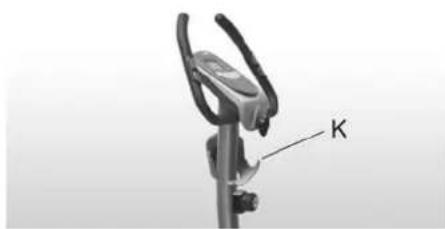
natural_image
Mechanical clamp device with labeled component 'K' (no text or symbols on the device itself)natural_image
Close-up of a RheMISHEY electric vehicle (no visible text or symbols on body)natural_image
Close-up of a medical or robotic device with a screw and shaft, no visible text or symbolsnatural_image
Close-up of a stationary exercise machine with visible joints and a screw, no text or symbols presentnatural_image
Close-up of a metallic cylindrical device with a small circular component attached (no visible text or symbols)natural_image
Mechanical assembly diagram showing a lever and shaft assembly with labeled parts A, B, C, D (no text or symbols present)natural_image
Close-up of a mechanical device with a curved pipe and attached lever, showing a small scale indicator (no text or symbols visible)natural_image
Close-up of a black cable with a fuse and connector, labeled 'F' (no text or symbols beyond label)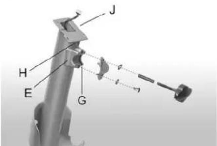
text_image
J H E Gnatural_image
Close-up of a mechanical device with a curved handle and lever mechanism (no visible text or symbols)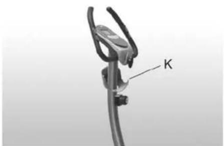
natural_image
Close-up of a mechanical clamp or bracket with a labeled component 'K' (no other text or symbols visible)natural_image
Mechanical assembly diagram showing two views of a stationary bike with labeled component 'L' (no text or symbols beyond basic labels)natural_image
Close-up of a BEEMSHEY 10 electric bike with attached cable and lever (no visible text or symbols)SENSORI NEL MANUBRIO
natural_image
Mechanical device with attached lever and adjustment knob (no visible text or symbols)natural_image
Close-up of a mechanical device with visible joints and components, no text or symbols presentnatural_image
Close-up of a metallic cylindrical device with a looped end, no visible text or symbolsnatural_image
Mechanical assembly diagram showing a shaft and lever with labeled parts A, B, C, D (no text or symbols beyond labels)natural_image
Close-up of a mechanical device with a curved pipe and attached lever (no visible text or symbols)natural_image
Close-up of a black cable with a labeled component 'F' and a small plug, no text or symbols present.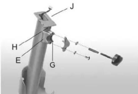
text_image
J H E Gnatural_image
Two-panel image showing a bicycle climbing device with a labeled component 'K' (no text or symbols on the device itself)natural_image
Mechanical diagram showing two views of a stationary exercise bike with labeled arm and foot (no text or symbols present)natural_image
Close-up of a BEMSHELEY U5 electric vehicle charging station (no visible text or symbols)TRANSPORT OCH FÖRVARING ....55
UNDERHÅLL 55
STÖRNINGAR VID ANVÄNDNING 55
TEKNISKA DATA 55
BRUKSANVISNING
natural_image
Close-up of a medical or rehabilitation device with adjustable arm and screw, no visible text or symbolsnatural_image
Close-up of a mechanical device with visible joints and a screw, no text or symbols presentnatural_image
Close-up of a metallic cylindrical device with a small circular component attached (no visible text or symbols)natural_image
Mechanical assembly diagram showing a shaft and housing with labeled parts A, B, C, D (no text or symbols beyond labels)natural_image
Close-up of a mechanical component with a curved pipe and a dashed line indicating a dimension (no text or symbols visible)natural_image
Close-up of a black cable with connectors and a labeled component 'F' (no text or symbols beyond the label)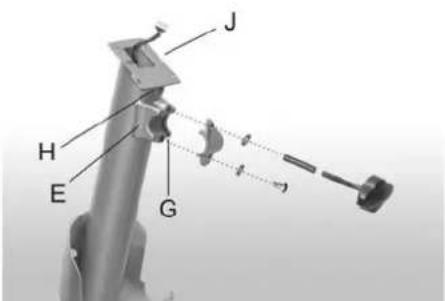
text_image
J H E Gnatural_image
Two identical diagrams of a bicycle bike climbing mechanism, showing hand positioning and labeled component 'K' (no text or symbols beyond labels)natural_image
Technical illustration of a stationary exercise machine with labeled components (no text or symbols present)natural_image
Close-up of a BEAMSHEY-branded exercise machine with attached cable and control lever (no visible text or symbols)natural_image
Close-up of a medical or rehabilitation device with a metallic tool and screw, no visible text or symbolsnatural_image
Close-up of a stationary exercise machine with visible legs and feet, no text or symbols presentnatural_image
3D rendering of a medical or laboratory device with a metallic rod and attached clip (no visible text or symbols)natural_image
Mechanical assembly diagram showing a shaft and housing with labeled components A, B, C, D (no text or symbols beyond labels)natural_image
Close-up of a robotic arm with a tool and mechanical components, no visible text or symbolsnatural_image
Close-up of a black cable with a labeled component 'F' and a small connector (no text or symbols beyond the label)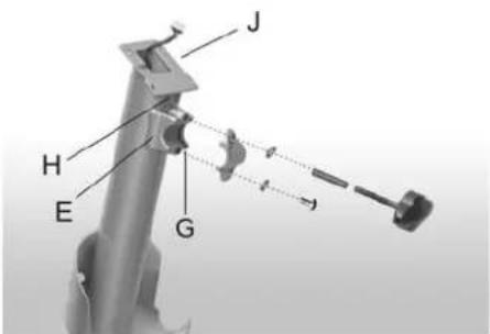
text_image
J H E Gnatural_image
Two-panel image showing a bicycle leaping mechanism with a labeled component 'K' (no text or symbols on the diagram itself)natural_image
Mechanical diagram showing two views of a stationary exercise bike with labeled lever (no text or symbols present)natural_image
Close-up of a BEEMSHEY electric vehicle (no visible text or symbols)text_image
Technical diagram of a mechanical assembly with numbered components and labeled parts
BATAVUS
Austria
DoWi GmbH
Ziehrerstrasse 80
8041 Graz
Tel. +43 316 71 64 12
Fax +43 316 71 64 35
www.dowi.at
Benelux
Batavus B.V.
Postbus 60001
1320 AA Almere
Nederland
Tel. +31 36 546 00 50
Fax +31 36 546 00 55
www.Batavus.nl
Finland
Batavus Oy Ltd
PL 750
20361 Turku
Tel. +358 2 513 31
Fax +358 2 513 3323
Germany
Batavus GmbH
Heidenfelder Str. 5
97525 Schwebheim
Tel. +49 9723 9345 0
Fax +49 9723 9345 19
www.Batavus.de
Great Brital
Bolton Stirland International Ltd.
Boland House
Nottingham South
Industrial Lane
Wilford
Tel. +44 115 98 22844
Fax +44 115 98 17784
www.bsfitness.co.uk
USA / Canada
Accell Fitness North America Inc.
130 Hayward Ave, Suite 2
N2C 2E4
Kitchener, ON Canada
Tel. 1-888-388-6887
Fax: 1-519-576-2521
www.accellfitness.com