360CB - Heating DOVRE - Free user manual and instructions
Find the device manual for free 360CB DOVRE in PDF.
Frequently Asked Questions - 360CB DOVRE
User questions about 360CB DOVRE
0 question about this device. Answer the ones you know or ask your own.
Ask a new question about this device
Download the instructions for your Heating in PDF format for free! Find your manual 360CB - DOVRE and take your electronic device back in hand. On this page are published all the documents necessary for the use of your device. 360CB by DOVRE.
USER MANUAL 360CB DOVRE
Installieconditions 4
Algemeen. 4
Schoorsteen 4
Declaration of conformity 3
Safety 4
Installation requirements..4
General 4
Flue or chimney 4
Ventilation of the area 5
Floor and walls 6
Product description 6
Installation 8
Preparation 8
Fitting the legs (350CB and 360CB only) 8
Fitting the handle holder 8
Preparing the connection to chimney. 9
Fitting the side panel (350CB3 and 360CB3
only) 10
Installing and connecting. 11
Use 11
First use. 11
Fuel 11
Lighting 11
Burning wood.12
Extinguishing the fire 13
Removing ashes 13
Fog and mist. 14
Solving problems 14
Maintenance 14
Chimney. 14
Cleaning and maintenance. 14
Appendix 1: Technical data 17
Appendix 2: Measurements. 18
Appendix 3: Distance from combustible
material 23
Appendix 4: Diagnostic diagram. 26
Index 27
Introduction
Dear user,
In buying this DOVRE heating appliance, you have chosen a high quality product. This product is part of a new generation of energy saving and environmentally friendly heating appliances. These appliances make optimal use of convection heat as well as thermal radiation (radiant heat).
- Your DOVRE appliance has been manufactured with state-of-the-art production equipment. In the unlikely event of a malfunction, you can always rely on DOVRE for support and service.
The appliance is not to be modified; always use original parts.
The appliance is intended for use in a living room. It must be connected hermetically to a well-functioning chimney.
We advise you to let an authorized and compete 60CB and 360CB3 have been produced in installation company install the appliance. conformity with EN 13240.
DOVRE cannot be held liable for any problems or damage resulting from incorrect installation.
Observe the following safety rules when installing and using the appliance.
In this manual, you can read how the DOVRE heating appliance can be installed, used and maintained T. C safely. Should you require additional information or technical data, or should you experience an installation problem, please contact your supplier first.
© 2012 DOVRE NV
Due to continuous product improvement, specifications of the appliance supplied may vary from the description in this brochure without prior notice.
DOVRE N.V.
Nijverheidsstraat 18 Tel: +32 (0) 14 65 91 91
B-2381 Weelde Fax: +32 (0) 14 65 90 09
Belgium E-mail: info@dovre.be

Safety
Please note: All safety regulations must be complied with strictly.
Carefully read the instructions for installation, use and maintenance before you start using the appliance.
The appliance must be installed in accordance with the laws and requirements of your country.
All local regulations and the regulations relating to national and European standards must be observed when installing the appliance.
Read the instructions for installation, use and maintenance supplied with the appliance.
It is preferable to have the appliance installed by an authorized and competent installation company. They will be aware of the applicable regulations and requirements.
The appliance is designed for heating purposes. All surfaces, including the glass and the connecting tube, can get very hot (over 100^ ! For operation, use a so-called "cold hand" or an oven glove.
Don't place any curtains, clothes, laundry or other combustible materials on or near the appliance.
Don't use flammable or explosive substances near the appliance when it is in use.
Avoid a chimney fire by having the chimney swept regularly. Never burn wood with an open door.
In the case of a chimney fire: close all air of the appliance and alert the fire brigade.
If the glass in the appliance is broken or cracked, it must be replaced before you can use the appliance again.
Make sure there is adequate ventilation in the room where the appliance is installed. The combustion will be incomplete in case of insufficient ventilation, which results in toxic gases being produced and spread through the room. See the chapter "Installation requirements" for more information on ventilation.
Installation requirements
General
The appliance must be connected tightly to a well-functioning chimney.
For the connection measurements: see the appendix "Technical data".
Ask the fire brigade and/or your insurance company about any specific requirements and regulations.
Flue or chimney
The flue or chimney is needed for:
Disposing of the combustion gases through natural draught.
The warm air in the flue or chimney is lighter than the outside air so it rises.
The intake of air, needed for the combustion of fuel in the appliance.
open A poorly functioning flue or chimney can cause smokers to escape into the room when the door is opened.
mamage caused by smoke emissions into the room is not covered by the warranty.
Do not connect multiple appliances (such as a boiler for central heating) to the same flue, unless local or national regulations allow this.
Ask your installer for advice regarding the flue. Refer to the European norm EN13384 for a correct calculation for the flue.
The flue must satisfy the following requirements:
The flue or chimney must be made of fire resistance material, preferably ceramics or stainless steel.
The flue or chimney must be airtight and well cleaned and guarantee sufficient draught.
i
A draught/vaccuum of 15 - 20 Pa during normal operation is ideal.
Starting from the flue spigot, the flue must run a vertically as possible. Changes in direction and horizontal pieces disrupt the outward flow of combustion gases and may cause the deposit of soot.
The interior measurements should not be too big prevent the combustion gases from cooling down too much, thereby reducing the draught.
The flue or chimney must ideally have the same diameter as the connection collar.
i
For the nominal diameter: see the appendix "Technical data". If the smoke channel is well insulated, the diameter may be slightly bigger (up to 2x the section of the connection collar)
For good combustion, the appliance needs air (oxygen). That air is supplied via adjustable air inlets from the area where the appliance is installed.
The combustion will be incomplete in case of insufficient ventilation, which results in toxic gases being produced and spread through the area.
The section (area) of the smoke channel must constant. Wider segments and (in particular) narrower segments disrupt the outward flow of combustion gases.
- When using a cover plate or exhaust hood: measure that the cover does not restrict the flue out and that the cap does not impede the outward of combustion gases.
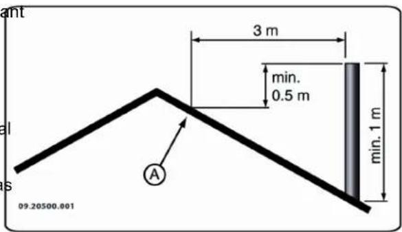
The chimney must end in a zone that is not affected by surrounding buildings, adjacent trees, other obstacles.
The chimney part outside the house must be insulated.
The chimney must be at least 4 metres high.
As a rule of thumb: 60cm above the ridge of the roof.
If the ridge of the roof is more than 3 metres away from the flue: stick to the measurements in the following figure. A = the highest point of the roof within a distance of 3 metres.
As a rule of thumb, the air supply should be 5.5cm^2 /kW Extra ventilation is needed when:
The appliance is in an area that is well insulated.
There is mechanical ventilation, for example a central extraction system or an extraction hood in an open kitchen.
You can provide extra ventilation by having a flow ventilation louvre installed in the outside wall.
Make sure that other air consuming appliances (such as tumble-driers, other heating appliances or a bath room fan) have their own supply of outside air, or are switched off when you use the appliance.
Floor and walls
The floor on which the appliance is placed must sufficient load bearing capacity. For the appliance weight: see the appendix "Technical data".

Protect a flammable floor from heat radiation by means of a fireproof protective plate. See the appendix "Distance from combustible material".

Remove combustible material such as linoleum, carpets/rugs and similar materials below the fireproof protective plate.

Keep enough distance between the appliance and combustible materials such as wooden walls and furniture.

The connecting tube radiates heat too. Ensure that there is sufficient distance or a shield between the connecting tube and combustible material.
The rule of thumb for a single-walled tube is a distance of 3x the diameter. If a lining shell is fitted around the tube, a distance of 1x the diameter is permissible.
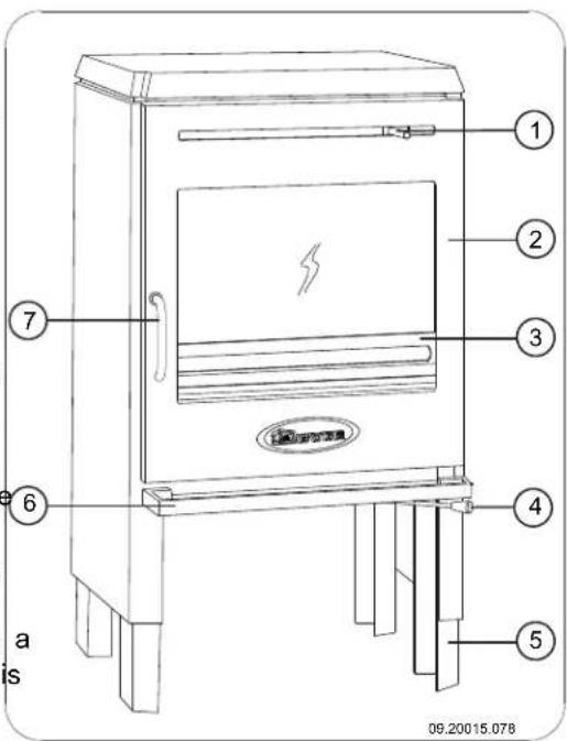
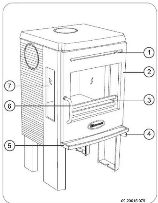
Product description
Model 350CB and 360CB

Carpets and rugs must be at least 80 cm away Air slide for secondary combustion air, air-wash air from the fire.

Protect a flammable floor from possible falling. 3. Fire basket ash in front of the fire with the aid of a fireproof
protective plate. The protective plate must comply with national standards.
-
Air slide for primary combustion air
-
Adjustable leg

For the dimensions of the fireproof protective plate: see the appendix "Distance from combustible material".
-
Ashtray
-
Bolt

For further requirements in connection with fireFeatures of model 350CB and 360CB
The appliance is supplied with height-adjustable legs.
The appliance can be connected to the chimney at the rear, at the upper side or at the side.
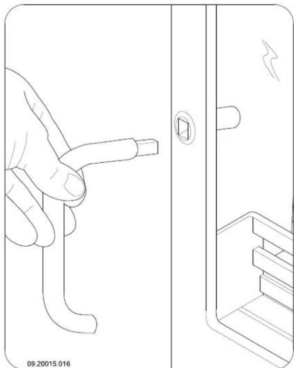
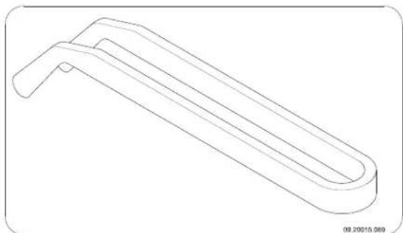
The appliance is supplied with a detachable handle.
In order to open the door, insert the detachable handle into the door; see the following figure.
In order to prevent the handle becoming warm during use, the handle can be placed in the holder underneath the appliance's ash tray.
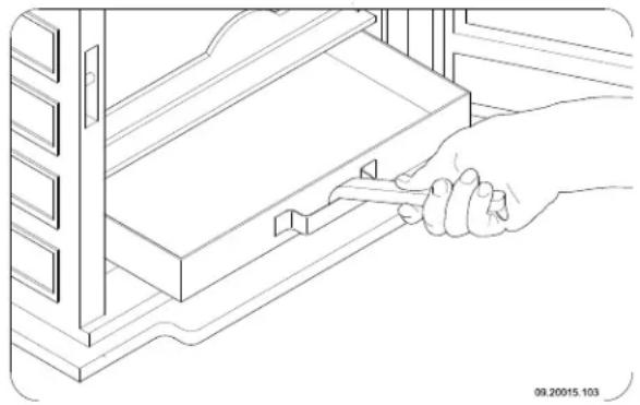
In order to remove the ash pan, the appliance is². Door fitted with a cast-iron detachable handle, the so-3. Fire basket called "cold hand"; see the following figure.
3. Fire basket
The appliance is supplied with a scraper for removing excess ash.
Model 350CB3 and 360CB3
-
Air slide for secondary combustion air, air-wash air
-
Air slide for primary combustion air
- Ashtray
- Bolt
- Side glass
Features of model 350CB3 and 360CB3
These models have the same features as models 350CB and 360CB, with the exception of the following points:
The appliance is not height-adjustable.
You can replace the side glass (7) with a side panel. In this case, the minimum distance between the side and combustible material decreases from 80 cm to 40 cm. The side panel is supplied as standard.
Model 350CB3/WB
Features of model 350CB3/WB
This model has the same features as model 350CB3.
The appliance is installed with a log compartment that is shut off by a door.
Installation
Preparation
- Please check the appliance for damage caused during transport or any damage or defects immediately after delivery.
If you detect damage caused during transport or any other damage or defects, do not use the appliance and notify the supplier.
- Remove the removable parts (fire-resistant inner plates, fire basket, ash pan, fire grate) from the appliance before you start installing the appliance.
i By removing removable parts, it is easier to move the appliance and to avoid damage.
Note the location of those removable parts, so that you have no difficulties in installing the parts in the right place later on.
-
Open the door.
-
Remove the fire-resistant inner plates.
i Cast iron inner plates protect the combustion chamber and dissipate heat to the environment.
Fitting the legs (350CB and 360CB only)
If desired, you can fit the appliance with height-adjustable legs. Fit the legs to the appliance; see the following figure.
theTilt the appliance on its back.
- Fit the height-adjustable legs (A) to the desired height using the bolts M6 (C) and washer (B) provided.
- Fit the appliance on the newly-fitted legs in the original position.
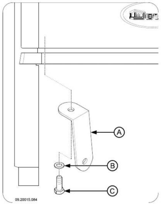
Fitting the handle holder
Fit the handle holder provided (A) to the base of the appliance using the washer (B) and the bolt M8 (C); see the following figure.
Preparing the connection to chimney
When connecting the appliance to the chimney you have the choice of connecting via either the upper side, the side or the rear. See the paragraphs "Connecting to the top side or on the side" and "Connecting to the rear".
The appliance is not supplied with a flue gas opening.
Sealant and materials supplied.
i
For Germany, the appliance is supplied with a connection collar with a diameter of 130~mm
When connecting to the upper side an opening has to be made in the heat shield. At the spot when the opening has to be made an incision has been made in the heat shield.
Preparation for connection at the rear side
Make the necessary opening in the heat shield.
- Unhook the heat shield from the appliance.
- Make the opening in the heat shield by cutting the pre-cut section out of the heat shield using plate shears.
- Replace the heat shield back onto the appliance.
Connecting to the upper side, re side or on the side
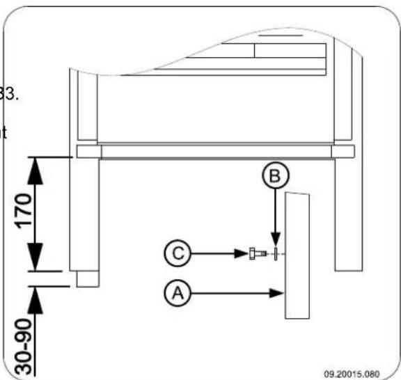
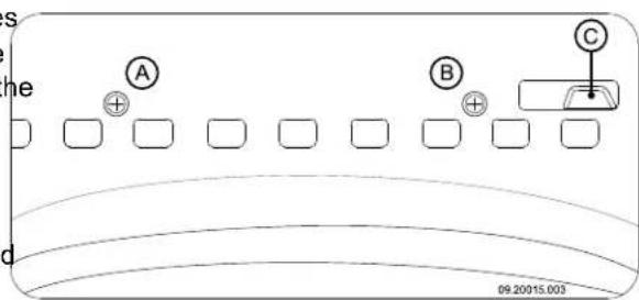
First make the flue gas opening in the appliance by removing the connection cover. Use the equipment provided: the tension piece, the washer, the nut and bolt; see following figure.
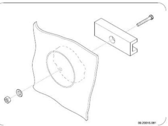
- In the centre of the connection cover, drill a hole with a diameter of 10mm
- Place the tension piece and the bolt on the inner side of the connection cover.
- Slide the washer over the bolt and tighten the nut onto the bolt.
On enamelled appliances, place a piece of cardboard measuring a minimum of 20~cm by 20cm between the washer and the appliance to protect against chipping of the enamel.
ndertighten the nut by hand.Use a small amount of grease to make it easier to turn the nut.
Using a ring spanner, tighten the nut so that the connection cover breaks out.
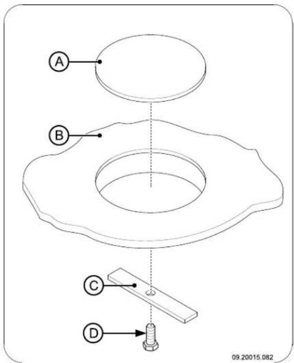
- Once made a flue gas opening can be closed off again with the supplied shut-off cover (A). Use the mounting plate (C) and bolt M6x25 (D) to fit the cover to the appliance (B); see the following figure.
7. Fit the connection collar (C) to the flue gas opening (D) using the two brackets supplied (E) and the fixing materials (A) and (B); see the following figure.
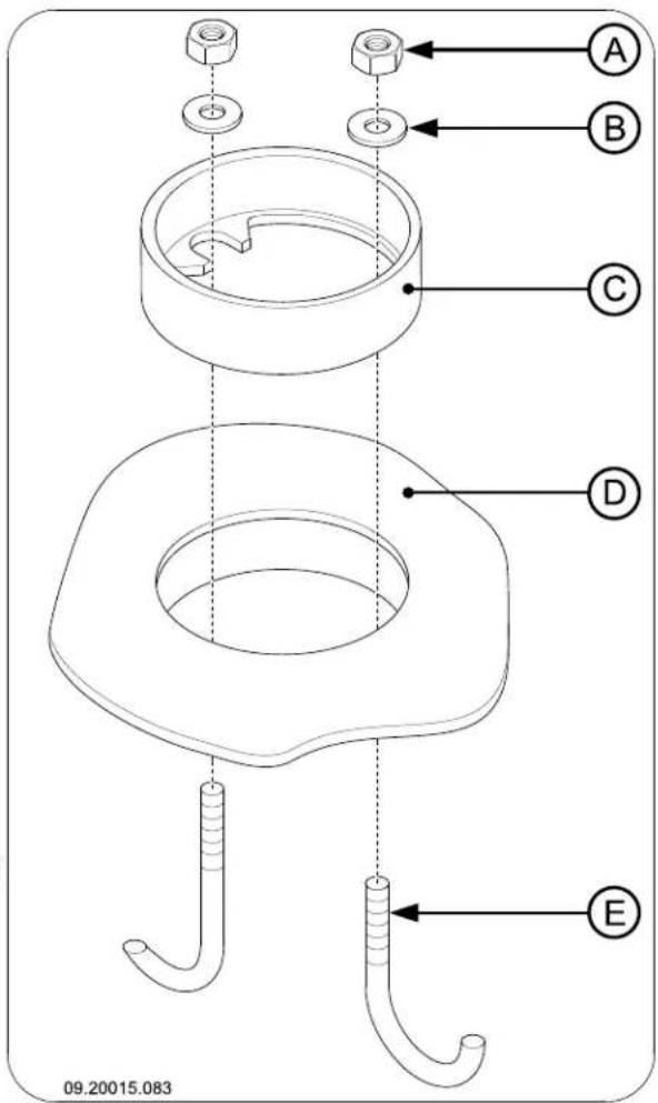
8. Use the supplied stove sealant to seal the connection collar and the cover to the appliance.
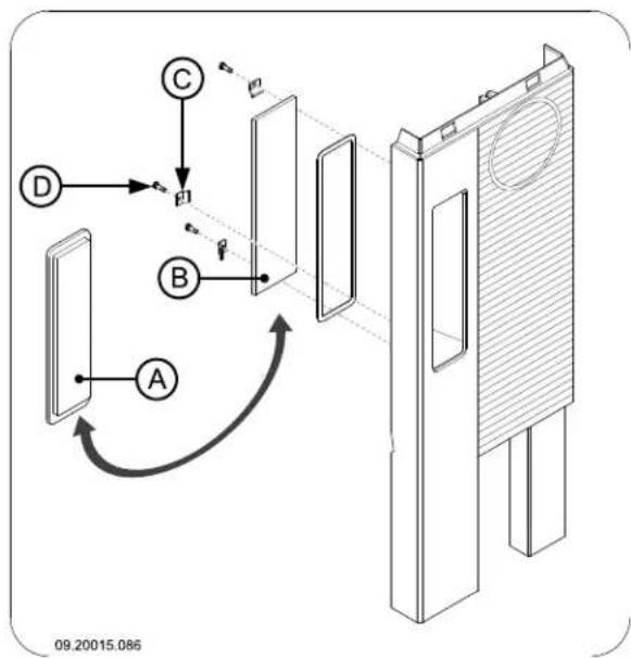
Fitting the side panel (350CB3 and 360CB3 only)
If required, you can replace the side glass with a closed side panel that is supplied as standard; see the following figure for installation instructions.
In this case, the minimum distance between the side and combustible material decreases from 80 cm to 40 cm.
Installing and connecting
-
Install the appliance in the right place, and make sure it is level.
-
Connect the appliance hermetically to the flue.
-
In the case of connection to outside air: connect the outside air supply to the connector you have fitted to the appliance.
-
Install all the parts you removed in the right places in the appliance.

Never use the appliance without the fireresistant inner sheets.
The appliance is now ready for use.
Use
First use
When you use the appliance for the first time, make Lighting an intense fire and keep it going for a good few hours.
This will cure the heat-resistant paint finish. This may you can check whether the flue has enough draught result in some smoke and odours. You could open by lighting a ball of paper above the baffle plate. A cold windows and doors for a while in the area where tflce often does not have enough draught and
appliance is located.
Fuel
This appliance is only suitable for the burning of natural wood; sawn and chopped wood that is
sufficiently dry.
Do not use other fuels, as they can lead to serious damage to the appliance.
You are not allowed to use the following fuels, as they pollute the environment and because they heavily soil the appliance and flue, which may lead to a chimney fire:
Treated wood, such as scrap wood, painted wood, impregnated wood, preserved wood, plywood and chipboard.
Plastics, scrap paper and domestic waste.
Wood
Hardwood, such as from oaks, beeches, birches and fruit trees, is the ideal fuel for your stove. This type of wood burns slowly with calm flames. Softwood contains more resins, burns faster and gives off more sparks.
Use dried wood that contains no more than 20% moisture. The wood must have dried for at least 2 years.
Saw the wood to size and split it when it is still fresh. Fresh wood is easier to split, and split wood dries more easily. Store the wood under a roof where the wind has wind free access.
Do not use damp wood. Damp logs do not produce heat as all of the energy is used in the evaporation of the moisture. This will result in a lot of smoke and soot deposits on the door of the appliance and in the chimney. The water vapour will condense in the appliance and can leak away through chinks in the appliance, causing black stains on the floor. It may also condense in the chimney and form creosote. Creosote is a highly flammable compound and may cause a chimney fire.
Lighting
a you can check whether the flue has enough draught by lighting a ball of paper above the baffle plate. A cold tflae often does not have enough draught and
consequently, some smoke may escape into the room instead of up the chimney. By lighting the fire in the way described here, you can avoid this problem.
-
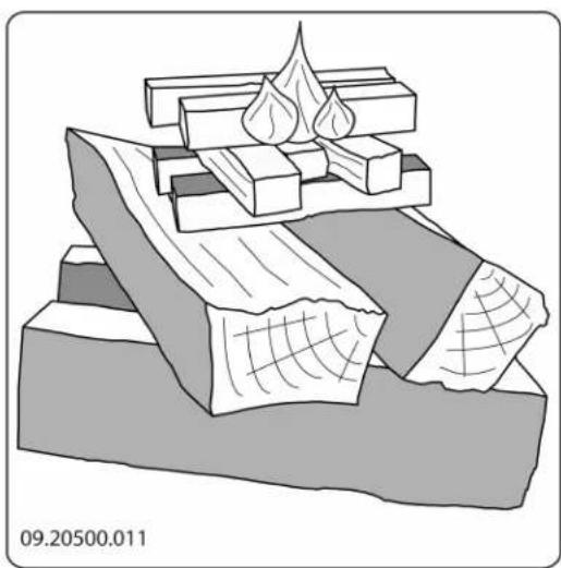
Stack two layers of medium sized logs crosswise1. Slowly open the door of the appliance.
-
Stack two layers of kindling crosswise on top of 2. Spread out the charcoal bed evenly across the the logs. bottom of the fire compartment.
-
Place a firelighter cube in the lower layer of kindling and light the cube according to the instructions on the packaging.
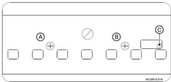
- Close the door of the appliance and open the primary air inlet and the secondary air inlet of appliance. The primary air inlet is open if the operating knob has been pulled out. The secondary air inlet is open if air slider (C) has slid left; see following figure.
- Let this fire develop into a good blaze until there glowing bed of charcoal. You can then add fuel and adjust the appliance, see the chapter "Stokin with wood".
Burning wood
After you have followed the instructions for lighting
- Spread out the charcoal bed evenly across the bottom of the fire compartment.
- Stack a few logs on the charcoal bed.
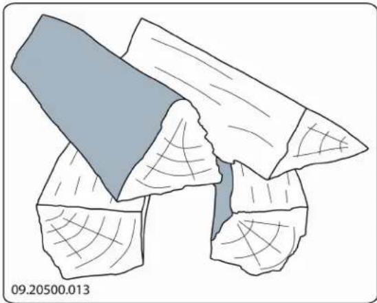
Open stacking
If the logs are stacked openly, the wood will burn quickly as the oxygen can reach each log easily. If you want to use the stove for a short while, make an open stack.
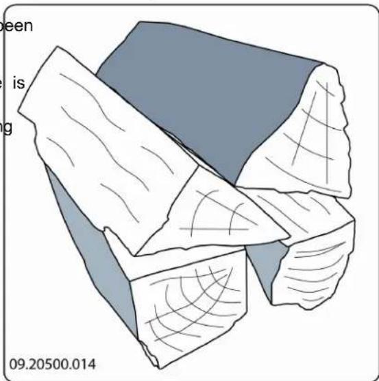
Compact stacking
If the logs are stacked tightly, the wood will burn more slowly as the oxygen can only reach some logs easily. If you want to burn wood for a longer period, make a compact stack.
-
Close the door of the appliance.
-
Close the primary air inlet and leave the secondary air inlet open. After

Fill the appliance up to one third capacity.
Advice

Never burn wood with an open door.

Regularly burn wood with intense roaring fires
If you frequently have low intensity fires, tar and creosote may be deposited in the chimney Tar and creosote are highly combustible substances. Thicker layers of these substances might catch fire when the temperature in the chimney increases suddenly and steeply. Therefore it is necessary for the fire to regularly burn very intensely, so that layers of tar and creosote disappear.
Low intensity fires also cause tar deposits on the stove window and door. When the outside temperature is not very low it is better to burn wood intensely for a few hours instead of having a low intensity fire for long period of time.
Control the air supply with the secondary air inlet

The secondary air inlet not only supplies air to the fire but to the glass as well, so that it does not get dirty so quickly.
- Open the primary air inlet for the time being if the supply by the secondary air inlet is inadequate or you want to fan the fire.
It is better to add a small amount of logs regularly than to add many logs at the same time.
Extinguishing the fire
Do not add fuel and just let the fire go out. If a fire damped down by reducing the supply of air, harmful substances will be produced and released. Therefore, let the fire go out naturally. Keep an eye on the fire until it has gone out. When the fire has died completely, all air inlets can be closed.
Removing ashes
After the wood has been burnt, a relatively small amount of ashes is left over. This bed of ashes is a good insulating layer for the bottom of the fire compartment and improves combustion. Therefore, you can leave a thin layer of ashes on the bottom of the fire compartment.
However, the air supply through the bottom of the fire compartment must not be impeded and no ash should be allowed to accumulate behind a cast iron inner plate. Therefore, remove any excess ash frequently.
eY: Open the door of the appliance.
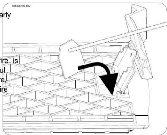
- Use the supplied scraper to open the de-ashing grate; see the following figure.
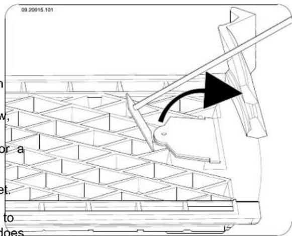
- Using the scraper, sweep the redundant ashes
the through the de-ashing grate into the ashtray or ifunderneath; see the following figure.
- Close the ash removal port.
- Remove the ash pan using the cast-iron "cold hand" and empty the ash pan; see the following figure.
- Install the ashtray and close the appliance door.
Fog and mist
Fog and mist hinder the flow of flue gases through subject to wear. Check the fire-resistant inner plates flue. Smoke can blow back and cause a stench. If it is frequently and replace them when necessary. not strictly necessary, it is better not to use the stove See the chapter "Installation" for instructions on in foggy and misty weather. removing and installing the inner plates.
Solving problems
Refer to the appendix "Diagnostic diagram" to solve any problems in using the appliance.
Maintenance
Follow the maintenance instructions in this chapter to keep the appliance in good condition.
Chimney
In many countries, people are legally required to have their chimney checked and maintained.
At the beginning of the heating season: have the chimney swept by an expert.
During the heating season and after the chimney has not been used for a long time: have the chimney checked for soot deposits.
After the heating season: seal off the chimney with a ball of paper.
Cleaning and maintenance

Do not clean the appliance when it is still warm.
Clean the exterior of the appliance with a dry lint-free cloth.
At the end of the heating season, you can clean the interior of the appliance thoroughly:
If necessary, first remove the fire-resistant inner plates.
If necessary, clean the air supply ducts.
- Remove the baffle plate at the top of the appliance and clean it. See the chapter "Installation" for instructions on removing and installing the baffle plate.
Checking fire-resistant inner plates
The fire-resistant inner plates are consumables and subject to wear. Check the fire-resistant inner plates frequently and replace them when necessary.
See the chapter "Installation" for instructions on removing and installing the inner plates.

The insulating vermiculite inner plates may develop hairline cracks, but that does not affect their performance adversely.

Cast-iron inner plates go a long way if you frequently remove the ash that may pile up behind them. If accumulated ash behind a cast-iron plate is not removed, the plate cannot dissipate the heat anymore to its surroundings and that may cause the plate to warp or crack.

Never use the appliance without the fire-resistant inner plates.
Removing the baffle plate
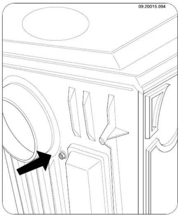
The baffle plate is secured with a bolt located between the rear connection and the secondary air duct. The bolt is fixed to the baffle plate.
- Remove the nut on the rear side; see the following figure.
-
Pull the baffle plate forwards so that the bolt comes free from the rear side.
-
Remove the baffle plate via the front door.
i
As the baffle plate has notches on both sides of it, the baffle plate can be taken along the ridges on the side walls and removed from the appliance without a problem.
Cleaning glass
Dirt clings less easily to well-cleaned glass. Proceed as follows:
-
Remove dust and loose soot with a dry cloth.
-
Clean the glass with stove window cleaner: a. Apply stove window cleaner to a kitchen sponge, rub down the entire glass surface give the cleaning agent time to react.
b. Remove the dirt with a moist cloth or kitchen tissue.
-
Clean the glass again with a normal glass cle product.
-
Rub the glass clean with a dry cloth or knife tissue.
Do not use abrasive or aggressive products to clean the glass.
Wear household gloves to protect your hands.
If the glass in the appliance is broken or cracked, it must be replaced before you can use the appliance again.
Make sure that no stove window cleaner runs between the glass and the cast-iron door.
Lubrication
Although cast-iron is slightly self-lubricating, you will still have to lubricate moving parts frequently.
Lubricate the moving parts (such as guide systems, hinge pins, latches and air slides) with heat resistant grease that is available in the specialist trade.
Adjusting the air slider
If the air slider (C) of the secondary air inlet does not move easily, you can adjust the air slider using the two screws (A) and (B) in the front plate; see following figure.
Touching up the finish
Small areas of damaged paint finish can be touched up with a spraying can of special heat-resistant paint finish available from your supplier.
Checking the seal
Check whether the sealing rope of the door is still nging in good condition and works well. The sealing rope is subject to wear and needs to be replaced in time.
Check the appliance for air leaks. Close any chinks with stove sealant.

Let the sealant harden fully before you start a fire in the appliance, because otherwise any moisture in the sealant will form bubbles in the sealant and cause a new air leak.
Appendix 1: Technical data
| Model | 350CB and 350CB3 | 360CB and 360CB3 | 350CB3/WB |
| Nominal output 6 kW 8 kW 6 kW | |||
| Flue connection (diameter) 125 mm 125 mm | 125 mm | ||
| Flue connection Germany (diameter) 130 mm | 130 mm 110 mm | ||
| Weight +/- 95 kg +/- 130 kg +/- 130 kg | |||
| Recommended fuel | Wood | Wood | Wood |
| Fuel property, max. length | 30 cm | 40 cm | 30 cm |
| Mass flow of flue gases | 6.6 g/s | 8.2 g/s | 6.6 g/s |
| Temperature increase measured in measuring section | 298 K | 297 K | 298 K |
| Temperature measured downstream from the spigot | flue 442 | 438 | 442 |
| Minimum draught | 12 Pa 10 Pa | 12 Pa | |
| CO emission (13%2) | 0,10 % | 0,10 % | 0,10 % |
| NOx emission (13%2) | 125 mg/Nm3 | 90 mg/Nm3 | 125 mg/Nm3 |
| CnHm emission (13%2) | 82 mg/Nm3 | 113 mg/Nm3 | 82 g/Nm3 |
| Particulate emission | 10 mg/Nm3 | 39 mg/Nm3 | 10 mg/Nm3 |
| Particulate emission in accordance with NS3059 | 3.58 gr/kg | 7.86 gr/kg | 3.58 gr/kg |
| Efficiency | 77 % | 75 % | 77 % |
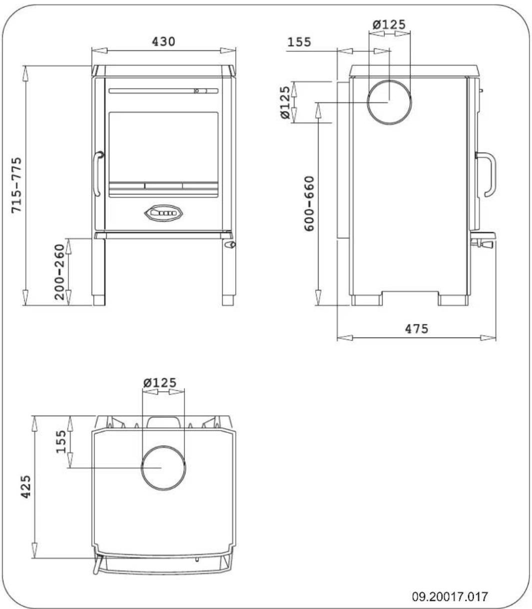
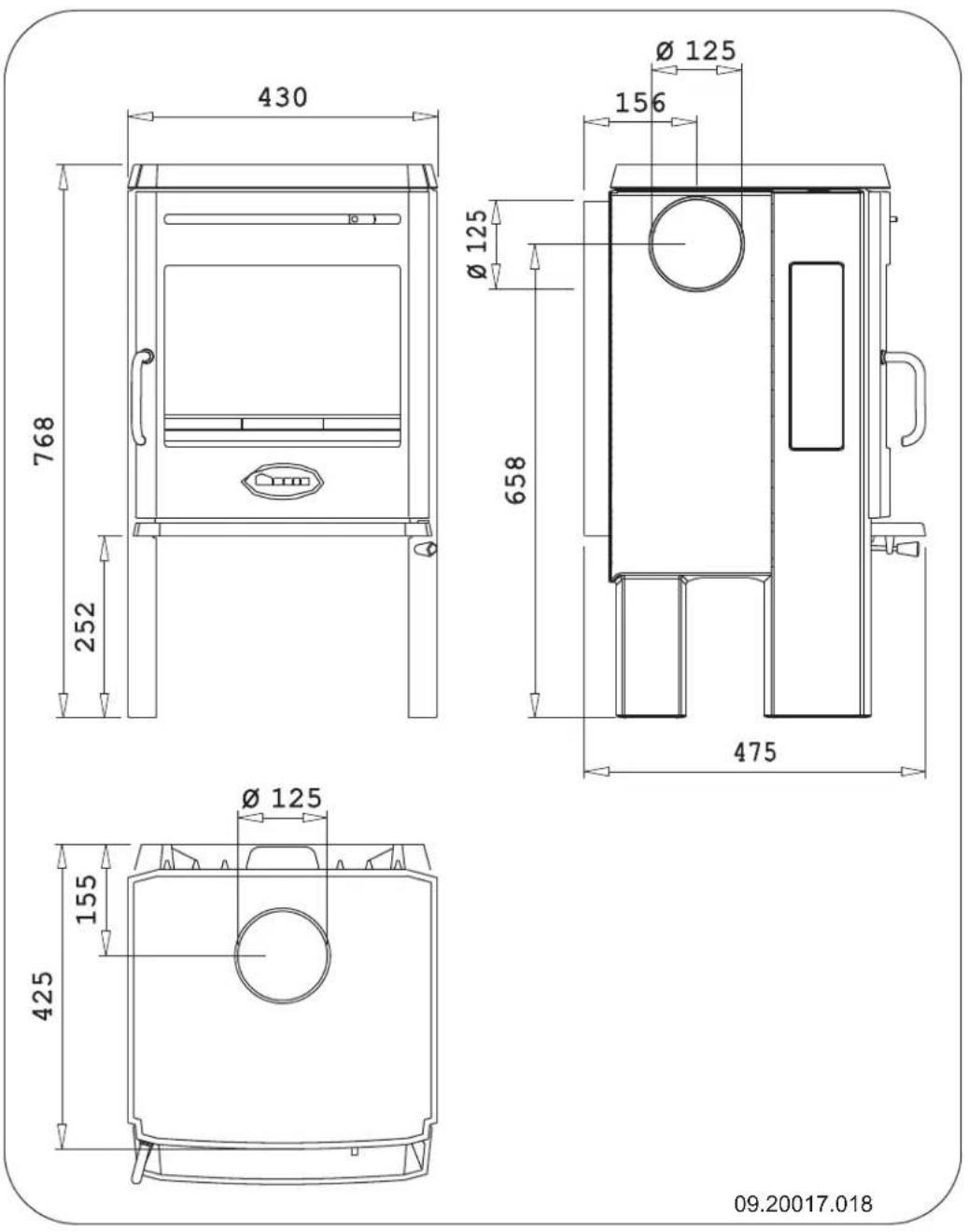
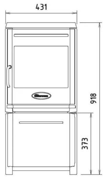
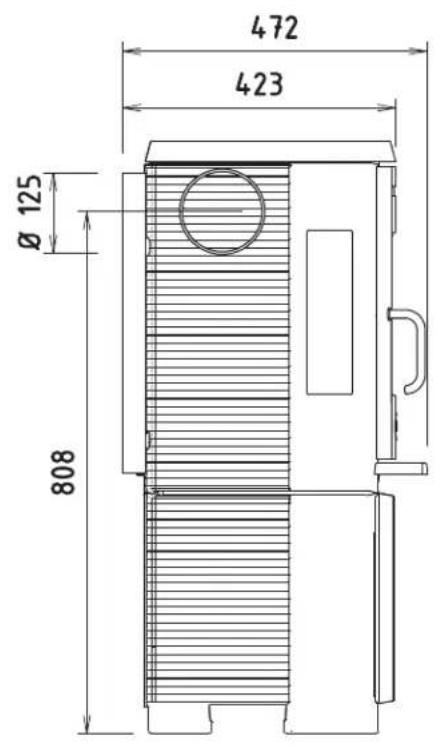
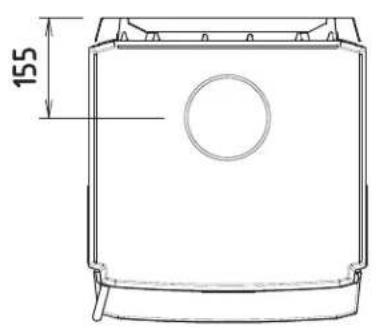
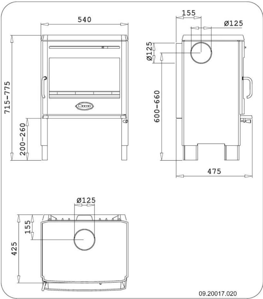
Appendix 2:Measurements
350CB
350CB3
350CB3/WB
09.20017.019
360CB
360CB3
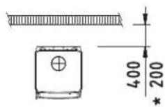
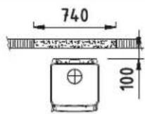
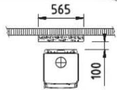
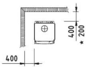
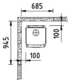
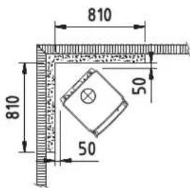
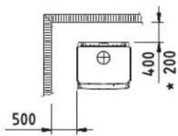
Appendix 3: Distance from combustible material
350CB, 350CB3, 350CB3/WB - Minimum distances in millimetres
09.20017.036
| * Protective (insulated) connection pipe | |
| Combustible material | |
| Incombustible material, thickness 100 mm | |
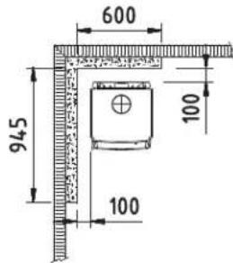
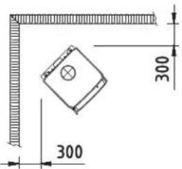
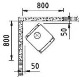
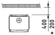
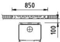
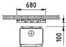
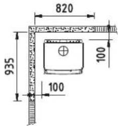
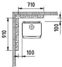
360CB en 360CB3 - Minimum distances in millimetres
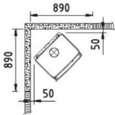
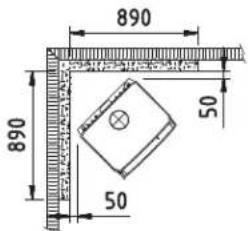
09.20017.037
| * Protective (insulated) connection pipe | |
| Combustible material | |
| Incombustible material, thickness 100 mm | |
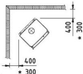
350CB, 350CB3, 350CB3/WB, 360CB and 360CB3 - Fireproof protective plate dimensions
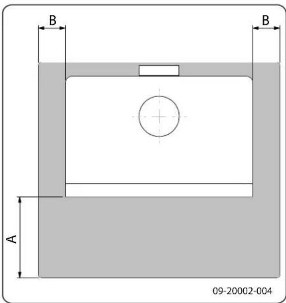
Minimal dimensions of fireproof protective plate
| A (mm) | B (mm) | |
| Din 18891 500 300 | ||
| Germany 500 300 | ||
| Finland 400 100 | ||
| Norway 300 100 |
Appendix 4: Diagnostic diagram
| Problem | ||||||
| ● | Wood does not keep burning | |||||
| ● | Gives off insufficient heat | |||||
| ● | Smoke emissions into the room when adding wood | |||||
| ● | Fire in appliance is too intense, is hard to adjust | |||||
| ● | Deposit on the glass | |||||
| Possible cause Possible | solution | |||||
| ● | ● | ● | ● | Insufficient draught | A cold flue usuallyfails to create sufficient draught. Follow the instructions for lighting in the "Use" chapter; open a window. | |
| ● | ● | ● | ● | Wood too damp Use wood with no more | more than 20% moisture. | |
| ● | ● | ● | ● | Pieces of wood too big | Use smallpieces of kindling. Use split logs no larger than 30 cm in circumference. | |
| ● | ● | ● | ● | ● | Wood stacked up incorrectly | Stackup the wood in a way that allows an adequate air flow between the logs (open stacking, see "Burning wood") |
| ● | ● | ● | ● | Chimney does not work properly | Check whether the chimney meets the requirements: at least 4 metres high, right diameter, well insulated, smooth inside, not too many bends, no obstructions in chimney (bird'snest, too much soot deposit), hermetically tight (no chinks). | |
| ● | ● | ● | ● | Chimney stack incorrect Sufficiently high | high above the roof, no obstacles in its vicinity | |
| ● | ● | ● | ● | ● | Air inlets set incorrectly Open the air | inletscompletely. |
| ● | ● | ● | ● | Appliance connected to chimney incorrectly | Connection should be hermetically tight. | |
| ● | ● | ● | ● | Vacuum in area where appliance is installed | Switch off extraction systems. | |
| ● | ● | ● | ● | Insufficient supply of fresh air | Provide an adequate air supply; if necessary use connection to outside air. | |
| ● | ● | ● | ● | Adverse weather conditions? Inversion (reversed air flow in chimney because of a high outside temperature) extreme wind velocities | We recommend you don't use the appliance in the case of inversion. Install an extra hood on the flue to increase the draught if need be. | |
| ● | Draught in the living room | Avoid draught in the living room, do not place the appliance near a door or heating air ducts. | ||||
| ● | Flames touch the glass | Make sure the wood does not lie too close to the glass. Slide the primary air inlet cover closer to the "Closed" position. | ||||
| ● | Appliance isleaking air Check the door seals and the appliance joints. | |||||
Index
A
Adding fuel 13
Adding wood smoke emissions into the room. 26
Air inlets.12 adjusting 15
Air leak 15.
Air supply for fire 13
Ash pan open.14
Ashes remove.13
B
Baffle plate removing.14.
Burning wood 12
add fuel. 13
adding logs. 12
appliance is hard to adjust. 26
fire is too intense. 26
insufficient heat. 14, 26
C
Carpet. 6
Chimney height 5
sweep 14
Chinks in appliance. 15
Clean glass. 15
Cleaning appliance. 14
Combustible material distance from 23
Connecting to the chimney 9
Connection measurements 18
Connection collar fitting 10
Connection cover removing 9
Connection to chimney rear side 9
Control air supply. 13
Cover on flue 5
Creosote 13
D
Damp wood 11
De-ashing grate removal. 13
Door sealing rope 15
Draught 17
Drying of wood. 11
E
Efficiency. 17
F
Filling height. 13
Finishing coat, maintenance 15
Fire extinguishing 13 lighting. 11
Fire-resistant inner plates maintenance. 14
Fire-resistant inner sheets warning 11
Fire going out. 13
Fire safety distance from combustible material 23
floor. 6
furniture 6
walls. 6
Floors fire safety. 6 load bearing capacity 6
Flue
connection diameter 17
connection to 11
maintenance 14
requirements 4
Flue gas mass flow. 17
Flue gas opening shutting off. 9
Fog,do not burn wood 14
Fuel
adding 13.
adding wood.13
necessary amount 14
suitable.11
unsuitable 11
G
Glass
clean.15
deposit 26
H
Handle holder
fitting.8.
Heat shield
making opening.9
removing 9
Heat, insufficient.14
Heat,insufficient.26
Hood on the flue. 5
1
Installation
measurements 18
K
Kindled fire 11
Kindling 26
L
Legs
fitting.8
Lighting 11
Load bearing capacity of floor 6
Lubricant. 15
Lubricate 15
M
Maintenance
chimney. 14
clean glass 15
cleaning the appliance. 14
fire-resistant inner plates 14
lubrication.15.
sealing 15
Measurements..18.
Mist, do not burn wood 14
N
Nominal output. 14, 17
0
Open
ash pan 14
P
Paint finish 11
Particulate emission. 17
Prevent a chimney fire 13
Primary air inlet. 12
R
Removal of ashes. 13
Remove ashes 13
s
Scaper for removing ash 7
Screens
clean 15
deposit 26.
Sealing rope for door 15
Secondary air inlet. 12
Side glass
replacing. 10
Side panel
fitting. 10
Smoke
on first use. 11
Smoke emissions into the room 4, 26
Softwood 11
Solving problems 14, 26
Stacking logs. 12
Storing wood 11
Stove window cleaner. 15
Suitable fuel 11
Supply of outside .air 5
connection to 11
Sweep chimney. 14
T
Tar. 13
Temperature 17
Temperature increase
measuring section 17
U
Unsuitable fuel.11
V
Ventilation.5
rule of thumb.5.
Ventilation louvre.5
W
Walls
fire safety.6.
Warning
chimney fire.4..11.13
combustible materials 4
fire-resistant inner plates..11.
glass broken or cracked 4, 15
hot surface 4
regulations 4
stove window cleaner. 15
terms and conditions for insurance 4
ventilation 4-5
Weather conditions, do not burn wood.
Weight 17
Wood 11
damp 11
does not keep burning 26
drying 11
right sort 11
storing 11
Table des matieres
Introduction 3
Plaque latereale montage. 10
Raccordement dimensions
Pose dimensions 18
Calor, insufficient 14, 26