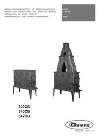
300CB - Heating DOVRE - Free user manual and instructions
Find the device manual for free 300CB DOVRE in PDF.
Frequently Asked Questions - 300CB DOVRE
User questions about 300CB DOVRE
0 question about this device. Answer the ones you know or ask your own.
Ask a new question about this device
Download the instructions for your Heating in PDF format for free! Find your manual 300CB - DOVRE and take your electronic device back in hand. On this page are published all the documents necessary for the use of your device. 300CB by DOVRE.
USER MANUAL 300CB DOVRE
Installiecondities 4
Declaration of conformity.2
Safety 3
Installation requirements 3
General.3
Chimney (flue).3.
Ventilation of the area.4
Floors and walls.4
Product description.5
Installation 5.
Preparation 5
Mounting the legs and ash drawer.. 6
Mounting the handle and operating knob.... 7
Preparing the connection to the flue 7
Installing and connecting .8
Use 8
First use. 8
Fuel 8
Lighting.8.
Burning wood 9
Controlling combustion air 9
Extinguishing the fire 10
Removing ash 10
Fog and mist 10
Solving problems 10
Maintenance 10
Chimney 10
Cleaning and other regular maintenance 11
300CB spare parts. 11
Appendix 1: Technical Data. 12
Appendix 2: Dimensions 13
Appendix 3: Distance from combustible
material 16
Appendix 4: Diagnosis diagram. 18
Index 19
Introduction
Dear user,
In buying this DOVRE heating appliance, you have chosen a high quality product. This product is part of a new generation of energy-efficient and environmentally-friendly heating appliances. These appliances make optimum use of convection heat as well as thermal radiation (radiant heat).
- Your DOVRE appliance has been manufactured with state-of-the-art production equipment. In the unlikely event of a malfunction, you can always rely on DOVRE for support and service.
The appliance should not be modified; please always use original parts.
The appliance is intended for use in a living room. It should be connected hermetically to a well-functioning chimney.
We advise you have the appliance installed by agence withEN 13240. authorized and competent installer.
DOVRE cannot be held liable for any problems or damage resulting from incorrect installation. Weelde 16-04-2013
Observe the following safety regulations when installing and using the appliance.
In this manual, you can read how the DOVRE heatingGehem
appliance can be installed, used and maintained safely. Should you require additional information or technical data, or should you experience an installation problem, please first contact your supplier.
© 2012 DOVRE NV
Due to continuous product improvement, the supplied appliance specifications may vary from the description in this brochure without prior notice.
DOVRE N.V.
Please note: All safety regulations must be complied with strictly.
Please read carefully the instructions supplied with the appliance for installation, use and maintenance, before using the appliance.
The appliance must be installed in accordance with the laws and requirements of your country.
All local regulations and the regulations relating to national and European standards must be observed when installing the appliance.
The appliance should preferably be installed by an authorized installer. Installers will be aware of the applicable regulations and requirements.
The appliance is designed for heating purposes. All surfaces, including the glass and connecting tube, can get very hot (over 100^ ! For operation, use a so-called "cold hand" or an oven glove.
Safety distances from flammable materials must be adhered to strictly.
Don't place any curtains, clothes, laundry or other combustible materials on or near the ap- ance.
Don't use flammable or explosive substances near the appliance when it is in use.
Avoid a chimney fire by having the chimney swept regularly. Never burn wood with the door open.
In the case of a chimney fire: close all air in of the appliance and alert the fire brigade.
If the glass in the appliance is broken or cracked, it must be replaced before you can use the appliance again.
Make sure there is adequate ventilation in the room where the appliance is installed. If ventilation is insufficient, combustion will be incomplete resulting in toxic gases being produced and spread through the room. See the chapter "Installation requirements" for more information on ventilation.
Installation requirements
General
The appliance must be connected tightly to a well-functioning chimney.
For the connection measurements: see the appendix "Technical data".
Ask the fire brigade and/or your insurance company about any specific requirements and regulations.
Chimney (flue)
The flue or chimney is needed for:
- Removal of combustion gases via natural draught.
As the warm air in the flue or chimney is lighter C)! than the outside air, it rises.
Air intake, needed for the combustion of fuel in the appliance.
A poorly-functioning flue or chimney can cause smoke to escape into the room when the door is opened. Damage caused by smoke emissions into the room is not covered by the warranty.
Do not connect multiple appliances (such as a boiler for central heating) to the same flue, unless local or national regulations allow this. In the event of two connections ensure that the difference in height between the connections is no less than 200mm .
Ask your installer for advice regarding the flue. Refer to the European norm EN13384 for a correct calculations for the flue.
The flue must satisfy the following requirements:
The flue or chimney must be made of fire-resistant material, preferably ceramics or stainless steel.
The flue or chimney must be airtight and well-cleaned and guarantee sufficient draught.
i
A draught/vacuum of 15 - 20Pa during normal operation is ideal.
-
Starting from the flue spigot, the flue must run as vertically as possible. Changes in direction and horizontal pieces disrupt the outward flow of comFor good combustion, the stove needs air (oxygen). combustion gases and may cause soot deposits. This air is supplied via adjustable air inlets from the To prevent combustion gases from cooling down area in which the stove is installed.
-
To prevent combustion, guess from cooling down too much, which reduces the draught, ensure that The combustion will be incomplete in case of the interior diameter is not too big. insufficient ventilation, which results in toxic
The flue or chimney should ideally have the same gases being produced and spread through the diameter as the connection collar.
For the nominal diameter: see the appendix As a rule of thumb, the air supply should be "Technical data". If the smoke channel is well 5.5cm^2/kW . Extra ventilation is needed when:
insulated, the diameter may be slightly bigger. The stove is in an area that is well-insulated. (up to 2x the section of the connection collar).
The section (area ) of the smoke channel must be constant. Wider segments and (in particular) narrower segments disrupt the outward flow of combustion gases. You can provide extra ventilation by having a ven
When using a cover plate or exhaust hood : make sure that the cover does not restrict the flue out. Take sure that other air consuming appliances (such as tumble-driers, other heating appliances or a bathroom fan) have their own supply of outside air, or
The flue must end in a zone that is not affected by surrounding buildings, trees or other obstacles.
The flue outside the house must be insulated.
The chimney must be at least 4 metres high.
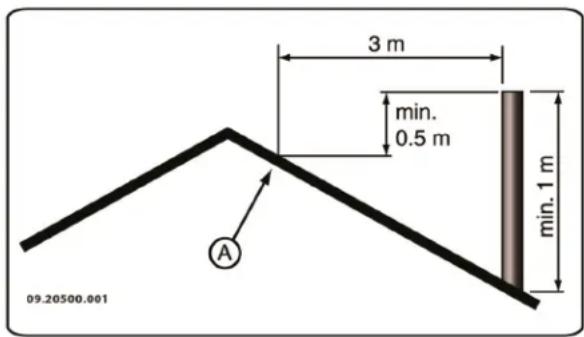
As a rule of thumb: 60cm above the ridge of thence, see the appendix "Technical data".
If the ridge of the roof is more than 3 metres away from the flue: stick to the measurements in the following figure. A = the highest point of the roof within a distance of 3 metres.
The floor on which the appliance is placed must have sufficient bearing capacity. For the weight of the appli
Hence, see the appendix "Technical data".
Protect flammable flooring from heat radiation by means of a fireproof protective plate. See the appendix "Distance from combustible material".
Floors and walls
Remove combustible material such as linoleum, carpets/rugs and similar materials below the fireproof protective plate.
Keep sufficient distance between the appliance and combustible materials such as wooden walls and furniture.
The connecting tube also radiates heat. Ensure that there is sufficient distance or a shield between the connecting tube and combustible material.
The rule of thumb for a single-walled tube is a distance of 3x the diameter. If a lining shell is fitted around the tube, a distance of 1x the diameter is permissible.

Carpets and rugs must be at least 80 cm away from the fire.

Use a fireproof floor plate to protect a flammable floor from any ash which may fall in fit of the stove. The protective plate must comply with national standards.

For the dimensions of the fireproof protective plate: see the appendix "Distance from combustible material".

For further requirements in connection with fire safety: see the appendix "Distance from combustible material".
Product description
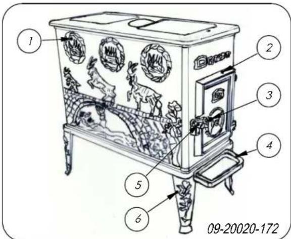
- Flue gas connection
- Door
- Air control scraper
- Ashtray
- Latch
- Leg
Features of the appliance
The appliance can be connected to the chimney the side, at the rear or at the upper side.
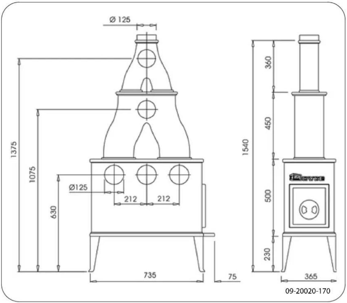
- Attachments are available for the appliance with the designation 400 - 200 which function as heat exchangers. See "Appendix 2: Dimensions of attachments. The stove can be connected at the side or on the upper side using these attachment
Preparation
Please check the appliance for damage caused during transport or any damage or defects immediately after delivery.

If you detect damage caused during transport or any other damage or defects, do not use the appliance and notify the supplier.

remove the detachable parts (vermiculite interior plates, baffle plate) from the appliance before you call it.

By removing removable parts, it is easier to move the appliance and to avoid damage.

Note the location of the removable parts, so that you can re-position the parts in the correct place later on.
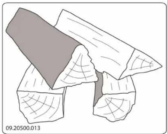
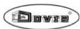
Removing inner plates

Vermiculite inner plates are light and tend to be ochrous in colour on delivery. They insulate the combustion chamber to boost combustion. Cast iron inner plates protect the combustion chamber and dissipate heat to the surroundings.
Top of inner plates
- Slide the inner plate at the top of the appliance forwards (1); see following figure.
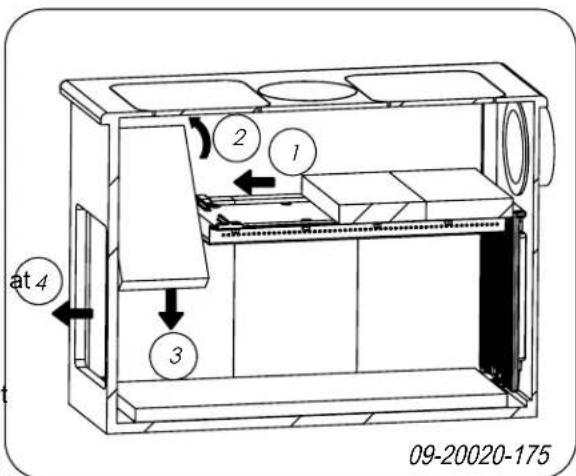

- Push the plate upwards so that you can tip it diagonally (2).
- Lower the plate to the bottom in the space (3).
- Remove the plate from the appliance using the door (4).
- Repeat instructions (1) to (4) for the two remaining plates.
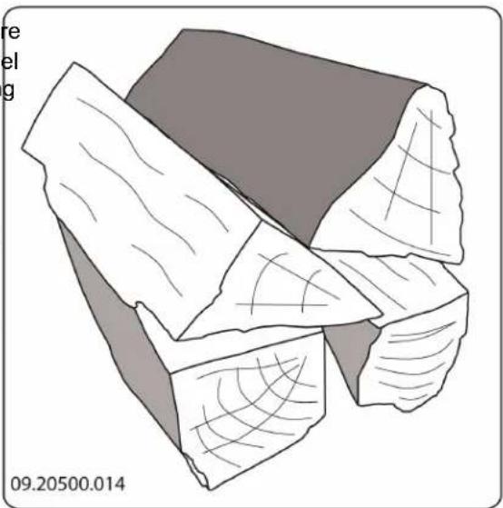
Sides of inner plates
- For both sides, slide the front inner plate forwards as far as possible (1); see following figure.
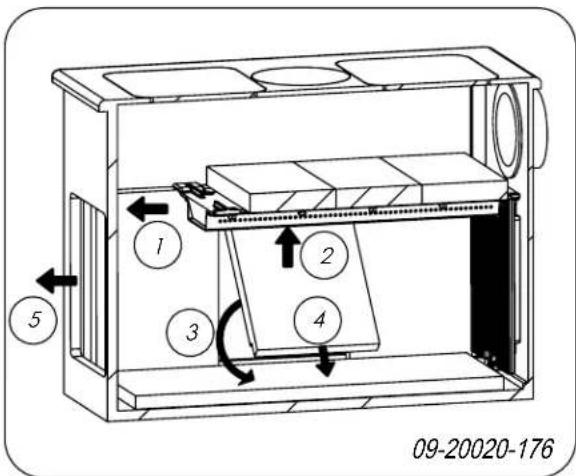
- Detach the baffle plate at the back by unscrewing the M8 screw (13mm) (2).
- Lift up the baffle plate from the back.
- Tip and lower the baffle plate (3).
- Remove the plate from the appliance using the door (4).
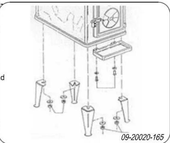
Mounting the legs and ash drawer
Fit the legs to the appliance; see the following figure.
- Push the second plate up a bit (2) and tip it diagonally (3) and (4).
- Remove the plate from the appliance through the door (5).
- Remove the third plate in the same way as the second one by repeating instructions (2) and (3).
- Slide the first plate into the position of the second plate and remove it in the same way.
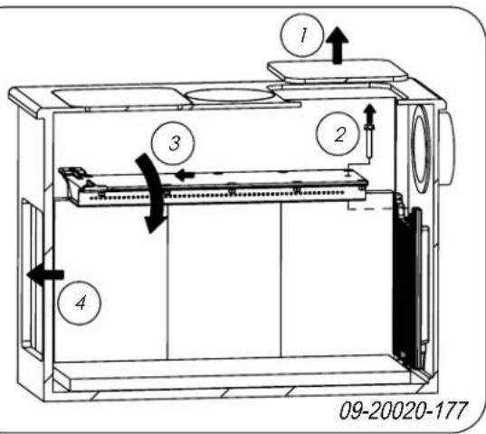
Baffle plate (chimney pipe plate)
- Take off the back cover (1); see following figure. You now have access to the combustion area from above.
- Tip the stove from the side.
-
Fit the four legs on the bottom plate using the washers and the M8 nuts that are found on the bottom plate.
-
Mount the ash drawer under the bottom plate below the door using the M8x12 screws
-
Set the appliance upright on the mounted legs.
Support the appliance when placing it upright to the flue from the the side, upper side or the rear. so that not all the weight is not on the legs.
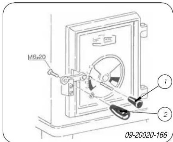
Mounting the handle and operating knob
Secure the handle using the M6x20 screw supplied(2) to the front piece and the operating knob for the air regulator (1); see following figure. 4
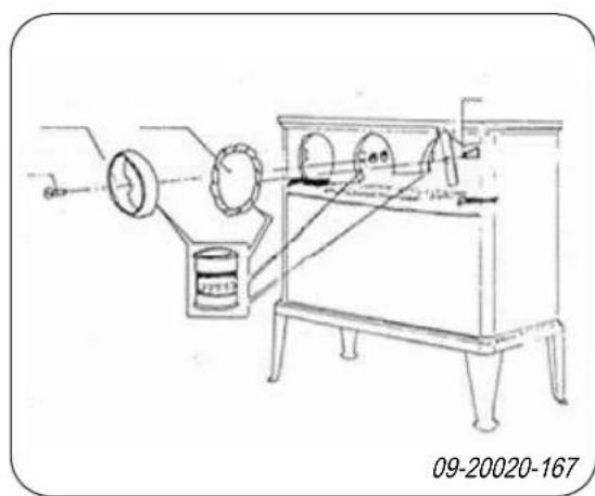
Connecting to the side, upper side or the rear
First of all, choose whether to connect the appliance to the flue from the the side, upper side or the rear.
- Mount the sealing collar (300-8) on the flue opening with the two screws and M8 nuts; see following figure.
- Apply sufficient sealant to the seal (300-7).
- Close off the other connection options with the (2) sealing covers and clamping plates supplied using air M6 screws.
- Use enough sealant
Preparing the connection to the flue
When connecting the appliance to the chimney you have the choice of connecting via either the side, the rear or the upper side. See the paragraph 'Connect to the side, upper side or rear'. It is also possible to make a connection using the 400-200 attachment that can be ordered separately; see the paragraph 'Connecting using attachments'.
Connecting using attachments
The 400 and 200 attachments increase the heat exchange area of the stove thereby making it more efficient. By using the optional attachments (sold separately), you can make side and upper connections.
ng Remove the covers on the upper side of the stove.
to
at Place the attachment onto the opening.
- Use the supplied stove sealant for sealing the attachment and the appliance.
The appliance is not supplied with a flue gas opa- ning.
Sealant and materials supplied.
Follow the instructions given in the paragraph 'Connecting to the side, upper side or rear' section to create the flue opening and to mount the collar connection supplied.
Installing and connecting
- Position the stove in the correct place, and make sure it is level.
- Connect the stove to the fuel hermetically.
- Re-position all removed parts in the correct places in the stove.
Never use the appliance without the ver-miculite inner plates.
The appliance is now ready for use.
Use
First use
When you use the stove for the first time, make an intense fire and keep it going for a good few hours. This will cure the heat-resistant paint finish. This may
result in some smoke and odours. You could open windows and doors for a while in the area in which the stove is located.
Fuel
This stove is only suitable for burning natural wood, sawn and chopped wood that is sufficiently dry.
Do not use other fuels, as they can cause serious damage to the stove.
You are not allowed to use the following fuels, as they place a firelighter cube in the lower layer of kind-pollute the environment and because they heavily soil ling and light the cube according to the instructions the appliance and flue, which may lead to a chimney on the packaging.
You can check whether the flue has sufficient draught by lighting a ball of paper above the baffle plate. A cold flue often has insufficient draught and consequently, some smoke may escape into the room instead of up the chimney. You can avoid this problem by lighting the fire as described below.
- Stack two layers of medium sized logs crosswise.
- Stack two layers of kindling crosswise on top of the logs.
fire:
Treated wood, such as scrap wood, painted wood, impregnated wood, preserved wood, plywood and chipboard.
Plastics, scrap paper and domestic waste.
Wood
Hardwood, such as oak, beech, birch and fruit tree wood is the ideal fuel for your stove. This type of wood burns slowly with calm flames. Softwood contains more resins, burns faster and sparks more.
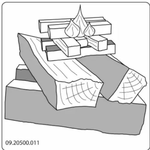
- Close the appliance door and completely open the compact stacking air slider in the door.
- Allow the fire develop into a good blaze until there is glowing bed of charcoal. You can then add fuel and adjust the appliance, see the chapter "Stoking with wood".
Burning wood
After you have followed the instructions for lighting :
- Slowly open the stove door.
- Spread the charcoal evenly across the bottom of the stove base.
- Stack a few logs on the charcoal.
Open stacking
If the logs are stacked openly, the wood will burn quickly as the oxygen can reach each log easily. If you want to use the stove for a short while, make open stack.
If the logs are stacked tightly, the wood will burn more slowly as the oxygen can only reach some logs easily. If you want to burn wood for a longer period, make a compact stack.
- Close the door of the appliance.
- Control the fire with the air slider in the door.

Fill the appliance half-way at most.
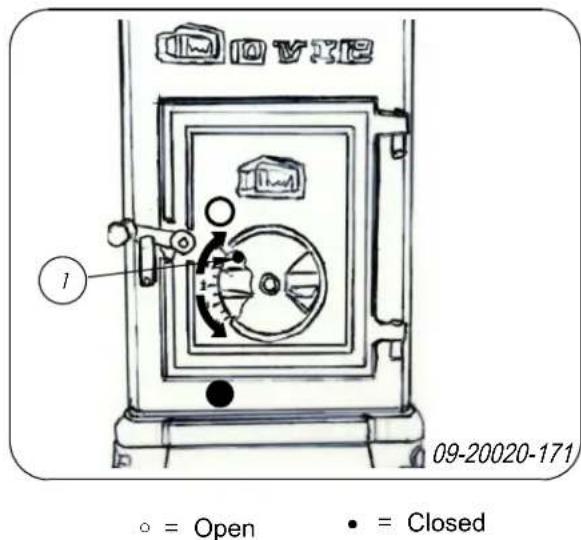
Controlling combustion air
The appliance has various features for air control; see following figure.
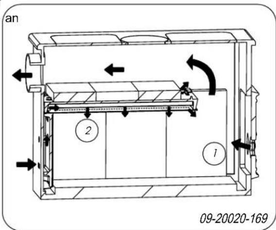
The main air vent (1) regulates the fire.
The baffle plate has permanent vents (2) that allow afterburning.
Advice

Never burn wood with an open door.

Stoke the fire regularly and thoroughly.
stances will be released. For this reason, the fire should be allowed to go out naturally. Keep an eye on the fire until it has gone out. All air inlets can be closed once the fire has died completely.
Removing ash
After the wood has been burnt, a relatively small amount of ashes is left over. This bed of ashes is a good insulating layer for the stove base plate and improves combustion. It is good to leave a thin layer of ashes on the stove base plate.
The flow of air through the fire plate must not be obstructed, however, and no ash may be allowed to accumulate behind a vermiculite inner plate. Remove the excess ash regularly.
You can remove the excess ash with the aid of a small shovel.
Fog and mist
Fog and mist hinder the flow of flue gases through the flue. Smoke can blow back and cause a stench. If it is not strictly necessary, it is better not to use the stove in foggy and misty weather.
If you frequently burn at a low setting, tar and creosote may be deposited in the flue. Tar are creosote are highly combustible substances.
Thicker layers of these substances may catchRefer to the appendix "Diagnostic diagram" to resolve fire if the temperature in the chimney increases any problems in using the stove.
suddenly. By burning the fire at a high intensity on a regular basis, any layers of tar and cre- osote will disappear.
Burning at a low intensity can also cause tarFllow the maintenance instructions in this chapter to be deposited on the stove window and door. keep the stove in good condition.
When the outside temperature is not very low,
it is better to burn wood intensely for a few hours instead of having a low intensity fire f long period of time.
Chimney
In many countries, you are required by law to have your chimney checked and maintained.
Control the air supply using the air vent in the
Always open the door carefully.
- Close the door immediately after adding fuel.
- Topping up with a few logs regularly is better than adding many logs in one go.
At the beginning of the heating season: have the chimney swept by an expert.
During the heating season and after the chimney has not been used for a long time: have the chimney checked for soot deposits.
After the heating season: seal off the chimney with a ball of paper.
Extinguishing the fire
Do not add fuel and just let the fire go out. If a fire is damped down by reducing the air supply, harmful
Cleaning and other regular Touching-up the paint finish maintenance Small areas of damaged paint finish can

Do not clean the stove when it is still warm.
finish available from your supplier.
Clean the exterior of the stove with a dry lint-free Checking the seal cloth.
Check whether the door sealing rope is still in good You can clean the stove interior thoroughly at the end condition and works well. The sealing rope is sub- of the heating season: ject to wear and will need to be replaced over time
- First remove any vermiculite inner plates. See the Check the appliance for air leaks. Close any chapter "Installation" for instructions on removing chinks with stove sealant. and installing the inner plates.
If necessary, clean the air supply ducts.
If the stove has a detachable baffle plate, remove the baffle plate at the top of the appliance and clean it. 300
Check the appliance for air leaks. Close any chinks with stove sealant.
Allow the sealant to harden fully before lighting the stove, as any moisture in the sealant will form bubbles, resulting in a new air leak.
Check whether the door sealing rope is still in good condition and works well. The sealing rope is subject to wear and will need to be replaced over time

Checking fire-resistant inner plates
The fire-resistant inner plates are consumables and subject to wear. Check the fire-resistant inner plates frequently and replace them when necessary.
See the chapter "Installation" for instructions on removing and installing the inner plates.

The insulating vermiculite or chamotte inner plates may develop hairline cracks, but this does not affect their performance adversely.

Cast-iron inner plates last a long time if you remove frequently the ash that can accumulate behind them. If accumulated ash behind the cast-iron plate is not removed, the plate will no
longer be able to dissipate the heat to the surPos. Part number Description Quantity roundings and this may cause the plate to warp 03.77520.000upper side inner plate 3 or crack. 2 03.77521.000side inner plate 6

Never use the stove without the fire-resistant inner plates.
Lubrication
Although cast-iron is slightly self-lubricating, you will still need to lubricate moving parts frequently.
Lubricate the moving parts (such as guide systems, hinge pins, latches and air slides) with heat resistant grease that is available in the specialist trade.
Appendix 1: Technical Data
| Model 300CB 340CB 342CB | |||
| Nominal output 9 kW 10 kW 10.5 kW | |||
| Flue connection (diameter) 125 mm 125 mm | 125 mm | ||
| Weight 115 kg 160 kg 180 kg | |||
| Recommended fuel | Wood | Wood | Wood |
| Fuel property, max. length | 60 cm | 60 cm | 60 cm |
| Mass flow of flue gasses | 5.8 g/s | 7.0 g/s | 7.5 g/s |
| Temperature increase measured in the measuring section | 301 °C | 208 °C | 196 °C |
| Temperature measured at appliance exit | 384 °C | 306 °C | 280 °C |
| Minimum draught | 12 Pa | 12 Pa | 12 Pa |
| CO emission (13%2) | 0.08 % | 0.10 % | 0.10 % |
| NOx emission (13%2)D | 84 mg/Nm3 | 76 mg/Nm3 | 82 mg/Nm3 |
| CnHm emission (13%2) | 52 mg/Nm3 | 142 mg/Nm3 | 127 mg/Nm3 |
| Particulate emission | 21 mg/Nm3 | 32 mg/Nm3 | 27 mg/Nm3 |
| Efficiency | 79.9 % | 83.1 % | 83.5 % |
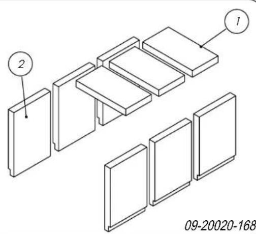
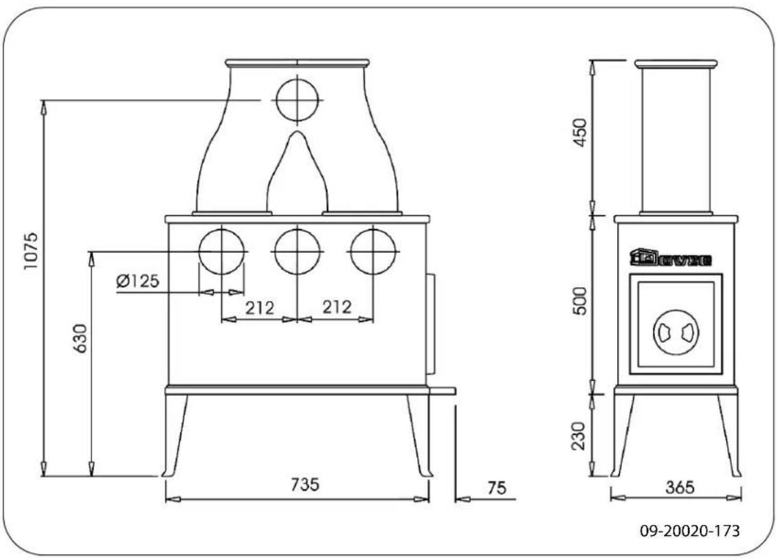
Appendix 2: Dimensions
300CB
Appendix 3: Distance from combustible material
300CB/340CB/342CB - Minimum distances in millimetres
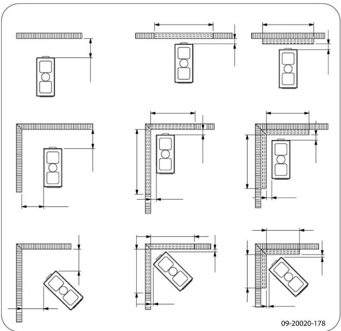
| Combustible material | |
| Incombustible material, thickness 100 mm |
300CB - Dimensions of fireproof floor plate
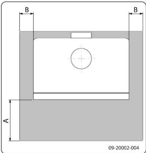
Minimum dimensions of fireproof floor plate
| A (mm) | B (mm) | |
| Din 18891 500 300 | ||
| Germany 500 300 | ||
| Finland 400 100 | ||
| Norway 300 100 |
Appendix 4: Diagnosis diagram
| Problem | |||||
| ● | Wood will not stay lit | ||||
| ● | Gives off insufficient heat | ||||
| ● | Smoke emissions into the room when adding wood | ||||
| ● | Fire in stove is too intense, is hard to adjust | ||||
| Deposit on the glass | |||||
| possible cause possible | solution | ||||
| ● | ● | ● | Insufficient draught | A cold flue usually failsto create sufficient draught. Follow the instruc-tionsfor starting a fire in the 'Use' section; open a window. | |
| ● | ● | ● | Wood too damp Use wood with no more than 20%moisture. | ||
| ● | ● | ● | Logs too large | Use small piecesof kindling. Use split logs no larger than 30 cm in cir-cumference. | |
| ● | ● | ● | ● | Wood stacked incorrectly | Stackthe logs in a way that allows adequate air flow between the logs (open stacking, see "Burning wood") |
| ● | ● | ● | Chimney does not work properly | Check whether the chimney meets the requirements: at least 4 metres high, correct diameter, well-insulated, smooth inside, not too many bends, no obstructions in chimney (bird'snest, too much soot deposit), hermetically tight (no chinks). | |
| ● | ● | ● | Chimney stack incorrect Sufficiently high | high above the roof, no obstacles in the vicinity | |
| ● | ● | ● | ● | Air inlets set incorrectly Open the air | inlets completely. |
| ● | ● | ● | Stove connected to the chimneyincor-rectly | Connection should be hermetically tight. | |
| ● | ● | ● | Vacuum in area in which the stove is installed | Switch off extraction systems. | |
| ● | ● | ● | Insufficient supplyof fresh air | Provide an adequate air supply; if necessaryuse outside air con- nection. | |
| ● | ● | ● | Bad weather? Inversion (reversed air flow in chim- because of a high outside temperature) If required, installan extra hood on the flue to increase the draught. extreme wind speeds | We recommend you don't use the appliance in the case of inversion. If required, installan extra hood on the flue to increase the draught. | |
| ● | Draught in the living room | Avoid draught in the living room, do not place the appliance near a door or heating air ducts. | |||
| ● | Flames touch the glass | Make sure the wood is not positioned too close to the glass. Slide the primary air inlet cover closer to the "Closed" position. | |||
| ● | Stove is leaking air Check the door seals and stove joints. | ||||
Index
A
Adding wood
smoking stove.18
Aerating the fire..10.
Air control.9
Air leak..11.
Ashes
remove.10.....
Attachment
heat exchanger.5
Attachments 400-200.7
B
Bearing capacity of floor 4.
Burning
appliance is hard to adjust 18
fire is too intense. 18
insufficient heat 18
topping up fuel. 10
Burning wood
adding logs. 9
insufficient heat 10
C
Carpet 4
Cast iron
fire resistant 5
inner plates. 5
Chimney
height 4
sweep 10
Chimney fire prevention. 10
Chinks in appliance 11
Cleaning
appliance 11
Cold hand
mounting 7
Combustible material
distance from 16
Connecting
dimensions 13
side 7
Connecting upper side
Connecting
rear 7
Control of air.
9
Controlling air supply.
10
Cover on flue.
4
Creosote
10
D
Damp wood.
8
Dimensions
13
Door
11
sealing rope 11
Draught
12
Drying wood.
8
E
Efficiency 12
F
Filling level of the appliance. 9
Finishing coat, maintenance. 11
Fire
extinguishing 10
lighting 8
Fire-resistant inner plates
maintenance 11
Fire going out. 10
Fire safety
distance from combustible material. 16
floor 4
furniture 4
walls 4
Fireproof inner plates. 8
Floors
bearing capacity. 4
fire safety 4
Flue
connecting to 8
connection diameter 12
maintenance 10
requirements 3
Flue gasses
mass flow. 12
Fog, do not burn wood
10
Fuel
adding 9
necessary amount 10
suitable .8.
topping up 10
unsuitable.8
wood 8.
G
Glass
deposit .18
H
Handle
mounting .7
Handle holder
mounting .7
Heat exchanger..7.
attachment .5
Heat, insufficient.10..18
Hood on the flue.4.
1
Inner plates
cast iron.5.
fireproof 8
vermiculite 5
Installing
dimensions 13
K
Kindled fire. 8
Kindling 18
L
Legs
mounting .6.
Lighting 8
Lubricant.11
Lubricate 11
M
Maintenance
chimney 10
Clean appliance 11
fire-resistant inner plates. 11
lubrication 11
sealing 11
measuring section 12
Mist, do not burn wood. 10
N
Nominal output 10, 12
P
Paint finish. 8
Particulate emission. 12
R
Removing ash 10
Removing ashes. 10
s
Screens
deposit .18
Sealing rope for door. 11
Smoke
on first use. 8
Smoke emissions into the room 3
Smoking stove. 18
Softwood
Solving problems. 10, 18
Stacking logs 9
Storing wood 8
Suitable fuel 8
Sweep chimney. 10
T
Tar 10
Temperature 12
Temperature increase. 12
Topping up with fuel 10
U
Unsuitable fuel 8
V
Ventilation 4
rule of thumb. 4
Ventilation louvre 4
Vermiculite
fire-resistant 5
Vermiculites inner plates
warning 8.
W
Walls
fire safety.4
Warning
chimney fire 3,8,10
combustible materials.3
glass broken or cracked 3
hot surface.3.
regulations 3
terms and conditions for insurance.3....
ventilation 3-4
vermiculite inner plates. 8
Weather conditions, do not burn wood. 10
Weight 12
Wood 8
damp 8
drying 8
right sort 8
storing 8
will not stay lit. 18
Table des matieres
Introduction 2