2510CTD - Fireplace DOVRE - Free user manual and instructions
Find the device manual for free 2510CTD DOVRE in PDF.

| Product type | Built-in fireplace (closed hearth) |
| Brand | Dovre |
| Model | 2510CTD |
| Nominal power (wood) | 10 kW |
| Energy efficiency (wood) | 80,0 % |
| Authorized fuels | Wood, lignite briquettes, anthracite |
| Max log length | 50 cm |
| Connection diameter | 150 mm |
| Height | 730 mm |
| Width | 610 mm |
| Depth | 630 mm |
| Weight | 180 kg |
| Power supply | 230 V ~ 50 Hz, 0,5 A |
| Main functions | Heating by convection and radiation, integrated thermostatic fans, air-wash system |
| Maintenance and cleaning | Regular cleaning of glass, refractory plates and flue; mandatory annual chimney sweeping |
| Safety | Safety distances: rear and sides 100 mm; protection of floor and flammable walls; thermal cut-off |
| Spare parts and repairability | Refractory plates, glass, gaskets, handle, fans; repair by approved professional |
| General information | Manufacturer: DOVRE NV, Belgium; standard EN 13240; manufacturer's warranty |
Frequently Asked Questions - 2510CTD DOVRE
User questions about 2510CTD DOVRE
0 question about this device. Answer the ones you know or ask your own.
Ask a new question about this device
Download the instructions for your Fireplace in PDF format for free! Find your manual 2510CTD - DOVRE and take your electronic device back in hand. On this page are published all the documents necessary for the use of your device. 2510CTD by DOVRE.
USER MANUAL 2510CTD DOVRE
INSTALLATION INSTRUCTIONS AND OPERATING MANUAL
INSTALLATION ET MODE D'EMPLOI
natural_image
Exterior view of a black industrial stove burner with visible flames and wood shavings (no text or symbols)
natural_image
Exterior view of a modern office building (no signage)
natural_image
Exterior view of a black rectangular stove burner with visible flames and wood shavings (no text or symbols)
natural_image
Exterior view of a modern black box with a lit interior showing flames and wood (no text or symbols visible)
natural_image
Exterior view of a modern stainless steel oven with visible flames and ventilation grilles (no text or symbols)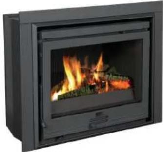
natural_image
Exterior view of a black rectangular energy heater with visible flames and wood shavings (no text or symbols)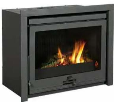
natural_image
Exterior view of a modern fire extinguisher (no signage or text visible)
natural_image
Black box-shaped stove burner with visible flames and smoke (no text or symbols)2020, 2200, 2210,
2220, 2500, 2510,
2520 en 2620
Inhoudsopgave
Inleiding 3
natural_image
Technical line drawing of a mechanical component with a U-shaped body and two protruding pins (no text or symbols)natural_image
Technical line drawing of a mechanical component with threaded shaft and flange (no text or symbols)natural_image
Diagram of a mechanical device with rotational arrows indicating motion, no text or symbols presentnatural_image
Technical line drawing of a mechanical device with mounting brackets and internal components (no text or symbols)natural_image
Technical line drawing of a mechanical device with mounting brackets and internal components (no text or symbols)natural_image
Technical line drawing of a structural support bracket with mounting holes and internal components (no text or symbols)natural_image
Technical line drawing of two structural components with a central labeled component 'A' (no text or symbols beyond labels)natural_image
Pure technical line drawing of a rectangular frame with an upward arrow, no text or symbols present
natural_image
Technical line drawing of a mechanical assembly with no visible text or symbolsnatural_image
Technical line drawing of a mechanical device with mounting holes and internal components (no text or symbols)Afwerking
natural_image
Illustration of layered geological strata with no visible text or symbolsnatural_image
Technical line drawing of a door frame with a spring and directional arrow (no text or symbols)Losse stapeling
natural_image
Illustration of a textured, folded object with no visible text or symbols
natural_image
Technical diagram of a door handle assembly with mounting holes and a hanging clip (no text or symbols)• = Dicht
○ = Open
Stoken met hout
natural_image
Illustration of a fragmented, irregularly shaped rock or mineral fragment with visible grain patterns (no text or symbols)natural_image
Line drawing of a rectangular container or tray with no text or symbolsnatural_image
Line drawing of a rectangular tray or container with a rectangular top and side handles (no text or symbols)
natural_image
Technical line drawing of a mechanical component (no text or symbols)text_image
Technical diagram showing installation of a fan or vent with labeled parts A and B, including a close-up view of the component.text_image
V1 V2 T1 230 VModel 2220, model 2520 en model 2620
text_image
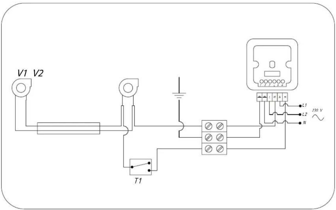
V1 V2 T1 L1 L2 N 230 VModel 2210 en model 2510
text_image
230 V N L2 L1 V1 V2 T1 L1Model 2200 en model 2500
text_image
V1 V2 R1 S1 A1 A2 A3 B4 B5 B6 L1 N 230 V L2Bruinkool as .... 21 stoken .... 21
Bruinkoolbriketten 19
Stof-emissie .26-27....
Performance declaration 4
Safety 8
Installation requirements...8.....
General 8....
Chimney (flue).8....
Ventilation of the area.9....
Floor and walls.9....
Product description 1.0....
Installation .11
Preparation 11
Building into an existing hearth.... 12
Building into a new hearth.... 13
Fitting outer frame.... 15
Use 16
First use.... 16
Fuel 16
Lighting 17
Burning wood 18
Burning brown coal briquettes.... 19
Burning anthracite coal 19
Controlling air combustion.... 19
Extinguishing the fire 20
Removing ash 20
Fog and mist 20
Solving problems 20
Maintenance 21
Chimney 21
Cleaning and other regular maintenance activities 21
Appendix 1: Technical data 23
Appendix 2: Connection diagrams..... 25
Appendix 3: Dimensions 28
Appendix 4: Distance from combustible material 37
Appendix 5: Diagnosis diagram.... 38
Index 39

Introduction
Dear user,
In buying this DOVRE heating appliance, you have chosen a high quality product. This product is part of a new generation of energy-efficient and environmentally-friendly heating appliances. These appliances make optimum use of convection heat as well as thermal radiation (radiant heat).
Your DOVRE appliance has been manufactured with state-of-the-art production equipment. In the unlikely event of a malfunction, you can always rely on DOVRE for support and service.
The appliance should not be modified; please always use original parts.
The appliance is intended for use in a living room. It should be connected hermetically to a well-functioning chimney.
We advise you have the appliance installed by an authorized and competent installer.
▶ DOVRE cannot be held liable for any problems or damage resulting from incorrect installation.
▶ Observe the following safety regulations when installing and using the appliance.
In this manual, you can read how the DOVRE heating appliance can be installed, used and maintained safely. Should you require additional information or technical data, or should you experience an installation problem, please first contact your supplier.
© 2012 DOVRE NV
Performance declaration
In accordance with construction products regulation 305/2011
No. 102-CPR-2013
- Unique identification number of the product type:
2020S / 2200 / 2210 / 2220
- Type, batch or serial number or other form of identification for the construction product, as scribed in article 11, subsection 4:
Unique serial number.
- Intended use for the construction product, in accordance with the applicable harmonised techr specification, as specified by the producer:
stove for solid fuel without production of warm water in accordance with EN 13240.
- Name, registered trade name or registered trademark and contact address of the producer, as scribed in article 11, subsection 5:
-
If applicable, name and contact address for the authorised whose mandate covers the tasks cified in article 12, subsection 2:
-
The system or systems for the assessment and verification of the performance durability of struction product, specified in appendix V:
System 3
- If the performance declaration concerns a construction product that falls under a harmonised
The appointed RRF instance, registered under the number 1625, has performed a type test under system 3 and has issued the test report no. 2905903.
-
If the performance declaration concerns a construction product for which a European technical assessment is issued:
-
Declared performance:
| The harmonised norm EN 13240 :2001/A2 :2004/AC :2007 | |||
| Essential characteristics | Performance Wood | Performance Brown coal | Performance Coal |
| Fire safety | |||
| Fire resistance A1 A1 A1 | |||
| Distance from combustible material (minimum distance in mm) | Rear: 100Side: 100 | Rear: 100Side: 100 | Rear: 100Side: 100 |
| Risk of glowing particles falling out Conform Conform Conform | |||
| Emission of combustion products | CO: 0.10%(13% O_2 ) | CO: 0.06%(13% O_2 ) | CO: 0.04%(13% O_2 ) |
| Surface temperature Conform Conform Conform | |||
| Electrical safety | - | - | - |
| Ease of cleaning | Conform Conform Conform | ||
| Maximum operating pressure | - | - | - |
| Flue gas temperature at nominal output | 295°C | 289°C | 272°C |
| Mechanical resistance(weight carry of chimney) | Not determined | Not determined | Not determined |
| Nominal output | 7 kW | 7 kW | 8 kW |
| Efficiency | 78.3 % | 75.4 % | 76.4 % |
- The performance of the product described in points 1 and 2 conform with the performance in point 9.
This performance declaration is supplied under the exclusive responsibility of the producer specifi in point 4:
text_image
T. Gehem26/08/2013 Weelde
Tom Gehem CEO

In accordance with construction products regulation 305/2011
No. 105-CPR-2013
- Unique identification number of the product type:
2500 / 2510 / 2520 / 2620
- Type, batch or serial number or other form of identification for the construction product, as scribed in article 11, subsection 4:
Unique serial number.
- Intended use for the construction product, in accordance with the applicable harmonised techr specification, as specified by the producer:
stove for solid fuel without production of warm water in accordance with EN 13240.
- Name, registered trade name or registered trademark and contact address of the producer, as scribed in article 11, subsection 5:
-
If applicable, name and contact address for the authorised whose mandate covers the tasks cified in article 12, subsection 2:
-
The system or systems for the assessment and verification of the performance durability of struction product, specified in appendix V:
System 3
- If the performance declaration concerns a construction product that falls under a harmonised
The appointed RRF instance, registered under the number 1625, has performed a type test under system 3 and has issued the test report no. 2905904.
-
If the performance declaration concerns a construction product for which a European technical assessment is issued:
-
Declared performance:
| The harmonised norm EN 13240 :2001/A2 :2004/AC :2007 | |||
| Essential characteristics | Performance Wood | Performance Brown coal | Performance Coal |
| Fire safety | |||
| Fire resistance A1 A1 A1 | |||
| Distance from combustible material (minimum distance in mm) | Rear: 100Side: 100 | Rear: 100Side: 100 | Rear: 100Side: 100 |
| Risk of glowing particles falling out Conform Conform Conform | |||
| Emission of combustion products | CO: 0.10%(13% O_2 ) | CO: 0.09%(13% O_2 ) | CO: 0.05%(13% O_2 ) |
| Surface temperature Conform Conform Conform | |||
| Electrical safety | - | - | - |
| Ease of cleaning | Conform Conform Conform | ||
| Maximum operating pressure | - | - | - |
| Flue gas temperature at nominal output | 264 °C | 318 °C | 314 °C |
| Mechanical resistance(weight carry of chimney) | Not determined | Not determined | Not determined |
| Nominal output | 10 kW | 10 kW | 10 kW |
| Efficiency | 80.0 % | 76.4 % | 79.0 % |
- The performance of the product described in points 1 and 2 conform with the performance in point 9.
This performance declaration is supplied under the exclusive responsibility of the producer specifi in point 4:
text_image
T. Gehem26/08/2013 Weelde
Tom Gehem CEO
Due to continuous product improvement, the supplied appliance specifications may vary from the description in this brochure without prior notice having been given.
DOVRE N.V.
Please note: All safety regulations must be complied with strictly.
through the room. See the chapter "Installation requirements" for more information on ventilation.

Please read carefully the instructions supplied with the appliance for installation, use and maintenance before using the appliance.
Installation requirements

The appliance must be installed in accordant with the legislation and requirements applicable in your country.
eGeneral

All local regulations and the regulations relating to national and European standards must be observed when installing the appliance.
The appliance must be connected tightly to a well-functioning chimney.
For the connection measurements: see the appendix "Technical data".

The appliance should preferably be installed by an authorised installer. Installers will be aware of the applicable regulations and requirements.
Ask the fire brigade and/or your insurance company about any specific requirements and regulations.

The appliance is designed for heating purposes. All surfaces, including the glass and connecting tube, can become very hot (over 100°C)! When operating, use a so-called "cold hand" or an oven glove.
Chimney (flue)
The flue or chimney is needed for:

Make sure there is sufficient protection if young children, disabled persons or old people are in the vicinity of the appliance.
▶ Removal of combustion gases via natural draught.

As the warm air in the flue or chimney is lighter than the outside air, it rises.

Safety distances from flammable materials must be strictly adhered to.
Air intake, needed for the combustion of fuel in the appliance.

Do not place any curtains, clothes, laundry or other combustible materials on or near the appearance.
A poorly-functioning flue or chimney can cause smoke to escape into the room when the door is opened. Damage caused by smoke emissions into the room is not covered by the warranty.

When in use, do not use flammable or explosive substances in the vicinity of the appliance.

Do not connect multiple appliances (such as a boiler for central heating) to the same flue, unless local or national regulations allow this. In the event of two connections ensure that the difference in height between the connections is no less than 200 mm.

Avoid chimney fires by having the chimney swept regularly. Never burn wood with the door open.
Ask your installer for advice regarding the flue. Refer to the European norm EN13384 for a correct calculations for the flue.

In the event of a chimney fire: close all the appliance's air inlets and alert the fire service.
The flue must satisfy the following requirements:

If the glass in the appliance is broken or cracked, it must be replaced before the stove, can be used again.
The flue or chimney must be made of fire-resistant material, preferably ceramics or stainless steel.

Ensure that there is adequate ventilation in the room in which the appliance is installed. If ventilation is insufficient, combustion will be incomplete whereby in toxic gases can spread
The flue or chimney must be airtight and well-cleaned and guarantee sufficient draught.
A draught/vacuum of 15 - 20 Pa during normal operation is ideal.
Starting from the flue spigot, the flue must run as vertically as possible. Changes in direction and horizontal pieces disrupt the outward flow of combustion gases and may cause soot deposits.
To prevent combustion gases from cooling down too much, which reduces the draught, ensure that the interior diameter is not too big.
The flue or chimney should ideally have the same diameter as the connection collar.
For the nominal diameter: see the appendix "Technical data". If the smoke channel is well insulated, the diameter may be slightly bigger (up to 2x the section of the connection collar).
The section (area) of the smoke channel must be constant. Wider segments and (in particular) narrower segments disrupt the outward flow of combustion gases.
When using a cover plate or exhaust hood : make sure that the cover does not restrict the flue outlet and that the cap does not impede the outward flow of combustion gases. The stove is in an area that is well-insulated. There is mechanical ventilation, for example a central extraction system or an extraction hood in an open kitchen.
The flue must end in a zone that is not affected by you can provide extra ventilation by having a vent- surrounding buildings, trees or other obstacles. ilation louvre fitted on the outside wall.
The flue outside the house must be insulated.
The chimney must be at least 4 metres high.
As a rule of thumb: 60 cm above the ridge of roof.
If the ridge of the roof is more than 3 metres from the flue: stick to the measurements in the lowing figure. A = the highest point of the roof within a distance of 3 metres.
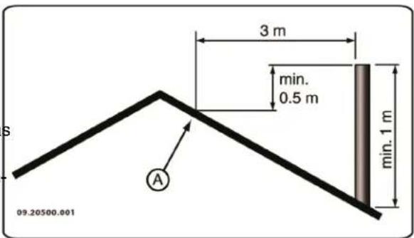
text_image
S 09.20500.001 A 3 m min. 0.5 m min. 1 mVentilation of the area
For good combustion, the stove needs air (oxygen). This air is supplied via adjustable air inlets from the area in which the stove is installed.

The combustion will be incomplete in case of insufficient ventilation, which results in toxic gases being produced and spread through the area.
As a rule of thumb, the air supply should be 5.5 cm²/kW. Extra ventilation is needed when:
The stove is in an area that is well-insulated. There is mechanical ventilation, for example a central extraction system or an extraction hood in an open kitchen.
d'by can provide extra ventilation by having a ventilation louvre fitted on the outside wall.
Make sure that other air consuming appliances (such as tumble-driers, other heating appliances or a bathroom fan) have their own supply of outside air, or are switched off when you use the appliance.
Floor and walls fol-
The floor on which the appliance is placed must have sufficient bearing capacity. The weight of the appliance is given in the appendix "Technical Data appendix".

There may not be any electrical wires in the floor below the appliance and in the walls around it.


All flammable materials must be removed from under the appliance or protected by at least a 6 cm concrete slab.

Flammable walls bordering the appliance must be protected by at least a 10 cm stone wall 5 cm insulation.

Protect non-flammable walls bordering the appliance with at least 2.5 cm insulation to avoid cracking.

Protect a flammable floor from heat radiation and falling ash by means of a fireproof protective plate. See the appendix "Distance from combustible material".

Keep enough distance between the appliance and combustible materials such as furniture.

Ensure sufficient ventilation around flammable materials such as a mantelpiece. See appendix "Distance from combustible material".

Carpets and rugs must be at least 80 cm away. Riddling rod from the fire.

Do not place any flammable materials within 50 cm of any convection outlets.
Product description
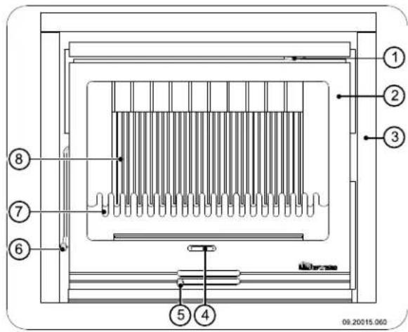
text_image
① ② ③ ④ ⑤ ⑥ ⑦ ⑧ 09.20015.060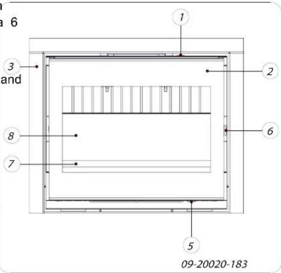
text_image
a 6 and 1 2 3 8 7 6 5 09-20020-183- Secondary air slide
- Door
-
Outside decorative frame
-
Riddling rod
-
Primary air slide
- Latch
- Fire basket
- Fireproof inner plates
Features of the appliance
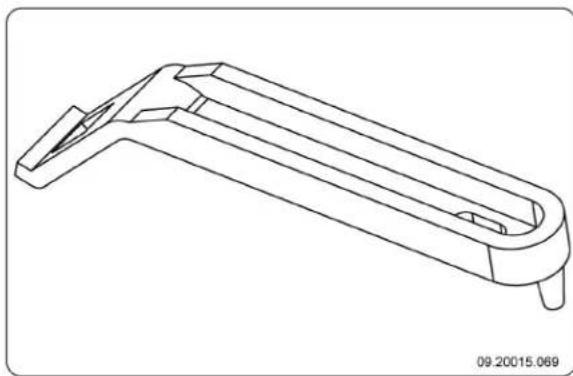
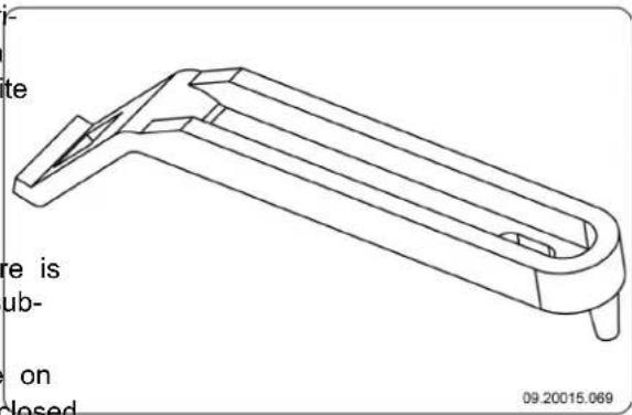
The appliance is supplied with a separate handle, the so-called 'cold hand', for opening the door.
The appliance is supplied with a second separate handle, the so-called 'cold hand', for removing the ash pan; see next figure.
natural_image
Technical line drawing of a mechanical component with a U-shaped body and two protruding pins (no text or symbols)
The opening direction of the door can be changed. The appliance is supplied with a door turning to the right. An optional locking rod is required for a left-turning door (supplied separately). The instructions for changing the door swing direction are provided with this locking rod.
The appliance is supplied with a connecting kit for the outside air supply.
The appliance is not suitable for continuous use.
The insert fireplace has an integrated convection system. This means that when installing the appliance it is not necessary for a separate convection space to be built and the use of air inlet and outgrates for convection is not necessary.
The space between the cast-iron fireplace and steel convection box serves as the convection space. Surrounding air is drawn in at the bottom of the appliance. The air is directed to the fireplace where it is heated. The heated air then leaves the front side of the convection space through the air opening on the upper side of the fireplace.
Installation the Preparation
Please check the appliance for damage caused during transport or any damage or defects immediately after delivery.
If you detect damage caused during transport or any other damage or defects, do not use the appliance and notify the supplier.
Remove the removable parts (fire-resistant inner plates, fire compartment, fire basket, ash removal port and ash pan) from the appliance before you start installing the appliance.
By removing removable parts, it is easier to move the appliance and to avoid damage. Note the location of the removable parts, so that you can re-position the parts in the correct place later on.
- Remove the fire-resistant inner plates.
i Cast iron inner plates protect the combustion chamber and dissipate heat to the surroundings.
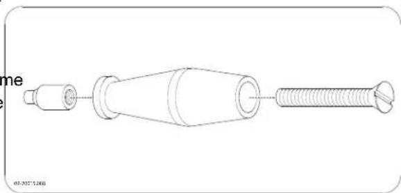
Fitting the handle
The appliance is supplied with a loose handle, the so-called "cold hand".
The form of the "cold hand" depends on the model of the appliance.
The appliance is equipped with two additional con- nections in order to transport convection heat to other areas.
The appliance is equipped with two built-in fans that aid convection. The turning speed of the fan can be adjusted using a speed control. This speed control is supplied with the appliance. The fan and speed control are connected to the mains electric
circuit; see paragraph "Connecting fan to the mains".

The fan works thermostatically. That meansFit the wooden handle to the adaptor using screw that the fan only starts to operate if the M8x50 provided; see following figure.
insert fireplace is sufficiently warm and the fan switches off once the insert fireplace has cooled sufficiently.
The appliance can be supplied with an outer frame to which you can attach a decorative frame. The decorative frame is supplied as an option.
natural_image
Technical line drawing of a mechanical component with threaded shaft and flange (no text or symbols)See the next figure for opening the door.

natural_image
Diagram of a mechanical device with rotating arrows indicating motion, no text or symbols presentChanging the opening direction the door
If desired, the opening direction of the door can be changed. The appliance is supplied with a door opening to the right. Follow the instructions below.
- Unscrew the door latch.
- Unscrew the locking cam from the post.
- Pull the hinge pins out of the hinges.
Be sure to support the door sufficiently; without the hinge pins, the door can come loose une2-pectedly.
- Remove the door from the appliance.
- Remove the washers from the hinge lobe and place them on the other side of the appliance.
- Position the door above the hinge lobes and insert the hinge pins into the hinges.
- Screw the latch onto the other side of the door.
- Screw the locking cam onto the other side of the door.
Comment: See the "Maintenance" chapter for adjusting the closing of the door.
Connecting the fan to the mains
The fireplace insert is supplied with two built-in fans and with a separate revolution control unit. The appliance is also fitted with a thermo switch that turns the fan on and off at a set temperature.
These parts must be connected to the mains as shown in one of the connection diagrams below.
The connection diagram is specific to the model.
Have the connection made by a qualified installer.
The fireplace insert is provided with a three-core cable.
The fireplace insert must be isolated from the mains by a 2-pole switch.
⚠ Ensure that the fireplace insert is properly earthed.
of See Appendix 2 for extended connection diagrams.
Building into an existing hearth
To build the stove into an existing hearth, follow the steps below:
- Place the appliance at the right height and level it.
⚠️ Keep the electrical cable of the appliance free.
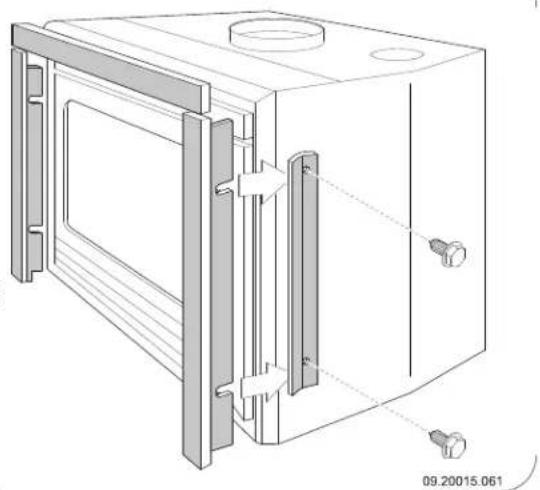
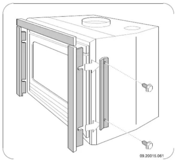
If you are going to put an external casing around the appliance, you should fit the clamping plates supplied to the sides of the appliance without fully tightening the screws. This is because the outside casing fits between the appliance and the clamping plates; see next figure.
natural_image
Technical line drawing of a microwave oven with mounting brackets and internal components (no text or symbols)
-
Close the base of the flue with incombustible material.
-
Make a 150 cm diameter opening in the base the extraction duct.
-
Centre the opening in the base on the connection collar on the stove.
-
Put the extraction duct in the opening. Make sure that the duct can be pulled down so that it fits in the connection collar. For example, use a variable-length duct.

If you are using a RFS-flexible duct: screw the duct onto the connector supplied, put the connector into the connection collar and secure the connector by bending the two lips outwards.
The figure below provides an example of the placing a fireplace insert in a hearth which is done using the instructions given above.
text_image
09.20015.058 A B C D E 3 mmA Existing hearth
B Ventilation space (minimum 15 mm)
C Existing flue
D Fireproof material or connector
E Opening to prevent pressure build-up
Building into a new hearth
The fireplace insert is installed in two stages:
Placing and connecting the fireplace
Building up the hearth around the fireplace.
Placing and connecting the fire-place insert
- Place the appliance at the right height and level it.
If you are going to put an external casing around the appliance, you should fit the clamping plates supplied to the sides of the appliance without fully tightening the screws. This is because the outside casing fits between the appliance and the clamp-
ofing plates; see next figure.

natural_image
Technical line drawing of a mechanical device with mounting brackets and internal components (no text or symbols)-
Check that there is at least 15 mm of free convection space between the existing walls - which must have the necessary insulation (see chapter "Installation Conditions") - and the back of the appliance.
-
The masonry should not rest on the fireplace. If required, use a support such as a steel beam. Leave a clearance of at least 3 mm between the support and the appliance.
-
Connect the appliance to the flue hermetically.
-
Check the draught in the flue and the seal of the connection on the flue gas duct by making a small,

intense trial fire with newspaper and dry, small 1. Lay the floor of the hearth.
kindling.

If there is new masonry then wait until the masonry has dried sufficiently.
Drawing off convection air
The appliance is equipped with two additional connections in order to transport convection heat to other areas. There must be air grids in these areas. If you wish to make use of this function, proceed as follows:

Make sure the door of the appliance can swing freely over the hearth floor.
- Build the hearth up to the smoke dome.

Ensure that a clearance of 2 mm is maintained between the appliance and the masonry to accommodate the thermal expansion of the fireplace.
- The inside of the hearth may, if desired, be clad-ded with reflective, insulating material.

Additional cladding of the built-in space prevents unnecessary thermal radiation to outer walls and/or adjacent rooms. It also prevents damage to the hearth wall insulation.
-
Remove the two push-out plates on top of the convection box by tapping them loose with a hammer
-
Fit the two connection collars supplied with a diameter of 125 mm on the resulting openings using the M8x16 screws and M8 bolts supplied.
-
Connect flexible tubing with a diameter of 125 mm and route them to the desired areas.
-
Connect the flexible tubing to the outlet grates in the rooms.
Build the rest of the hearth up to the flue opening hole in the ceiling.

The masonry should not rest on the fireplace. Use a support such as a steel beam. Leave a clearance of at least 3 mm between the support and the appliance.
Building the new hearth
Inside the hearth you provide space for convection. 5n Close the built-in space with the cover plate.
this space the air must be able to move freely. It must be possible for air to be sucked in for combustion, and the air heated by the fireplace (the convection air). Put an air grate below the cover plate to allow for the ventilation of the appliance.
must be able to flow freely into the area to be heated. Make an opening above the cover plate in order to see next figure. prevent any pressure build-up.
When building the hearth, follow these instructions: The figure below provides an example of the placing of a fireplace insert in a hearth which is done using the
The top of the hearth must be closed airtight using a cover plate of incombustible and heat-resistant material.
The cover plate must be level and placed at least 30 cm below the flue opening in the ceiling.
If desired, an additional outlet grate can be fitted at the top of the hearth, just below the cover plate.

Do not use combustible material in the hearth space and prevent thermal bridging by using materials that conduct heat.
Follow the instruction below when building the hearth:
Figure figure below provides an example of the placing of a fireplace insert in a hearth which is done using the instructions given above.
text_image
09.20015.057 A B C D E P F G H I N min 5 cm min 30cm J K O 3 cm L MA Flue
B Fireproof material or connector
C Cover plate
D Insulation material (minimum 5 cm)
E Fireproof wall
F Combustible wall
G Ventilation space (minimum 15 mm)
H Fireproof ceiling
I Combustible ceiling
J Convection air opening
K Insulation (optional)
L Fireproof base
M Combustible base
N Opening to prevent pressure build-up
O Connection pipe
P Convection air to another area
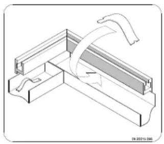
Fitting outer frame
The appliance can be supplied with a three- or four-sided outer frame. An optional decorative frame can also be supplied and that is fitted to the outer frame.
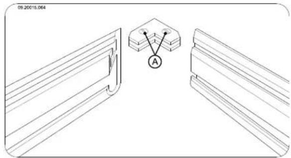
- Fit the outer frame by fitting the sides together with two screws; see next figure.
natural_image
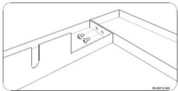
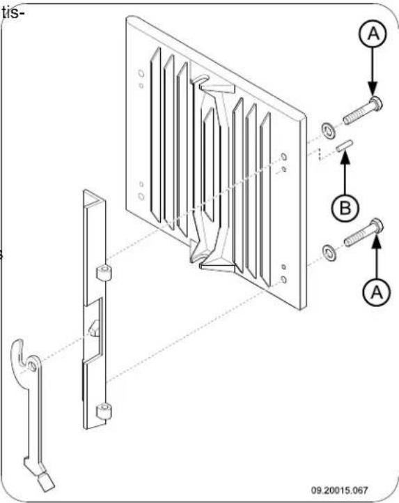
Technical line drawing of a structural support bracket with mounting holes and a wall-mounted component (no text or symbols)- Fit the decorative frame by joining the sides of the frame with a connecting element and fastening it with the two screws (A) of the connecting element; see next figure.
natural_image
Technical line drawing of a mechanical bracket with a labeled component 'A' (no text or symbols beyond label)- Centre the decorative frame on the outer frame; see next figure.
natural_image
Simple line drawing of a rectangular frame with an upward arrow and bottom base, no text or symbols present.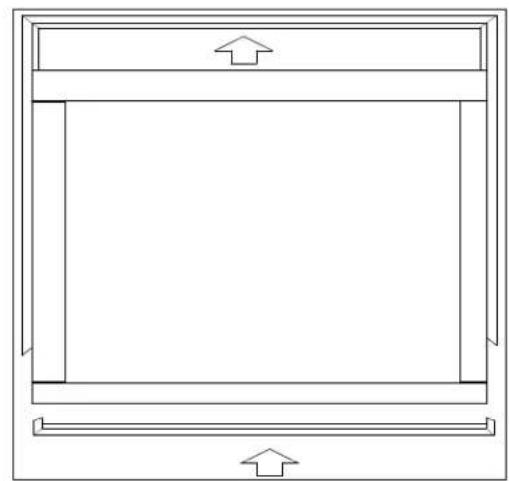
natural_image
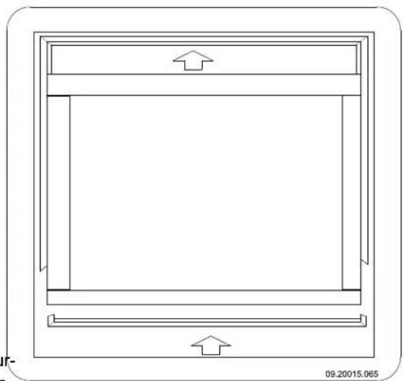
Simple line drawing of a rectangular frame with an upward arrow on top and bottom sides (no text or symbols)Put three supporting plates on each side between the decorative and the outer frame; see next figure.

natural_image
Technical line drawing of a mechanical assembly with no visible text or symbols- Attach the (assembled) frame to the appliance by sliding the tabs on the vertical sides of the frame between the appliance and the clamping plates; see next figure.
natural_image
Technical line drawing of a mechanical housing or enclosure with mounting flanges and bolted components (no text or symbols)Finishing
- Re-position all removed parts in the correct places in the appliance.
- Ensure that the newly built hearth is sufficiently dry before you start to use the appliance.

Never use the appliance without the fire-resistant inner plates.
The appliance is now ready for use.
Use
First use
When you use the stove for the first time, make an intense fire and keep it going for a good few hours.
This will cure the heat-resistant paint finish. This may Brown coal briquettes have approximately the same result in some smoke and odours. You could open burning characteristics as wood.
windows and doors for a while in the area in which the stove is located.
Fuel
The appliance is suitable for burning natural wood (sawn, split and sufficiently dry), brown coal briquettes and anthracite coal.
Do not use other fuels, as they can cause serious damage to the stove.
You are not allowed to use the following fuels, as they pollute the environment and because they heavily soil the appliance and flue, which may lead to a chimney fire:
▶ Treated wood, such as scrap wood, painted wood, impregnated wood, preserved wood, plywood and chipboard.
Plastics, scrap paper and domestic waste.
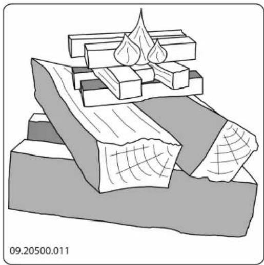
Wood
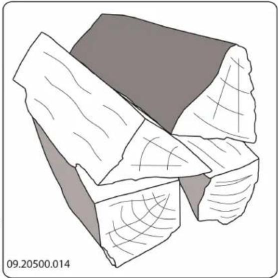
Hardwood, such as oak, beech, birch and fruit tree wood is the ideal fuel for your stove. This type of wood burns slowly with calm flames. Softwood contains more resins, burns faster and sparks more.
▶ Use seasoned wood that contains no more than 20% moisture. The wood should have been seasoned for at least 2 years.
▶ Saw the wood to size and split it while it is still fresh. Fresh wood is easier to split, and split wood dries more easily. Store the wood under a roof where the wind has free access.
Do not use damp wood. Damp logs do not produce heat as all the energy is used in the evaporation of moisture. This will result in a lot of smoke and soot deposits on the stove door and in the chimney. The water vapour will condense in the stove and can leak away through chinks in the stove, causing black stains on the floor. It may also condense in the chimney and form creosote. Creosote is a highly flammable compound and may cause a chimney fire.
Brown coal briquettes
▶ Ensure there is a good charcoal bed before you start burning brown coal briquettes.
For lighting the fireplace, follow the instructions in the "Lighting" paragraph.
Anthracite coal
Anthracite coal is categorised on the basis of characteristics, sometimes prescribed by law, such as the percentage of volatile substances. The ash content of anthracite coal is between 3% and 13%. The lower the ash content, the higher the net heating value and the less often you have to remove ash.
▶ Preferably use category A anthracite coal with a low ash content.
▶ Use the recommended size 12/22 or 20/30.
For lighting the fireplace, follow the instructions in the "Lighting" paragraph.
Lighting
You can check whether the flue has sufficient draught with wood".
by lighting a ball of paper above the baffle plate. A cold
flue often has insufficient draught and consequently, some smoke may escape into the room instead of the chimney. You can avoid this problem by lighting the fire as described below.
natural_image
Illustration of layered geological strata with no visible text or symbols- Close the door of the appliance and open the primary air inlet and the secondary air inlet of the appliance; see the following figure.
- Allow the fire develop into a good blaze until there is glowing bed of charcoal. You can then add fuel and adjust the appliance, see the chapter "Stoking
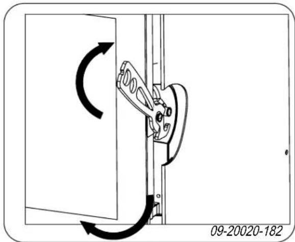
Operating the air slides
The appliance has two air slides. The primary air slide at the bottom of the door regulates the air under the grid. The secondary air slide above the door regulates
- Stack two layers of medium sized logs crosswisethe air for the glass (air wash system).
- Stack two layers of kindling crosswise on top of The air slide can be operated using the "cold hand". The logs. The form of the "cold hand" depends on the model of
- Place a firelighter cube in the lower layer of kind- ling and light the cube according to the instructions on the packaging. The appliance. See the following figure for the open and closed pos- itions of the air slide.
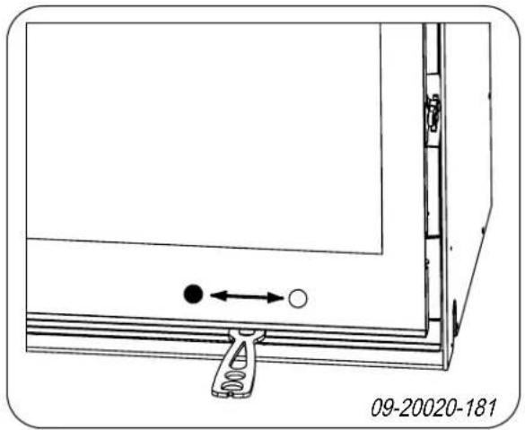
natural_image
Diagram of a door frame with a spring and directional arrow, no text or symbols presentOpen stacking

natural_image
Illustration of a textured, folded object with layered surfaces (no text or symbols)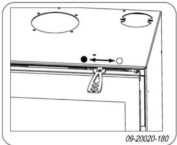
natural_image
Technical diagram of a mechanical assembly with mounting holes and a hanging clamp, showing directional arrows (no text or symbols)- = Closed
○ = Open
Burning wood
After you have followed the instructions for lighting :
- Slowly open the stove door.
- Spread the charcoal evenly across the bottom of the stove base.
- Stack a few logs on the charcoal.
If the logs are stacked openly, the wood will burn quickly as the oxygen can reach each log easily. If you want to use the stove for a short while, make an open stack.
Compact stacking
natural_image
Illustration of fragmented, irregularly shaped objects with internal patterns (no text or symbols)If the logs are stacked tightly, the wood will burn more slowly as the oxygen can only reach some logs easily. If you want to burn wood for a longer period, make a compact stack.
- Close the door of the appliance.
- Close the primary air inlet and leave the secondary air inlet open.

Fill the appliance up to one third capacity.
Burning brown coal briquettes
Brown coal briquettes burn in almost the same way wood. Using the primary air inlet, ensure sufficient supply of air under the fire. For further information the paragraph "Burning wood".
Burning brown coal briquettes creates a lot of as Regularly remove excess ash. See the paragraph "Removing ashes" for instructions.

For the properties and use of brown coal briquettes: consult your brown coal briquettes supplier or see the brown coal briquettes' packaging.
After you have followed the instructions for lighting:
- Slowly open the door of the appliance.
- Spread the charcoal evenly across the bottom of 8, the stove base.
- Place the brown coal briquettes on the charcoal bed.
- Close the door.
Burning anthracite coal
Use a coal basket to keep the anthracite coal in; following figure. The coal bin is available as an o
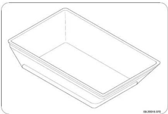
natural_image
Line drawing of a rectangular container or tray with no text or symbols
Always close the secondary air slide when burning anthracite coal.

Open the fire grate by pulling the riddling rod ward.
After you have followed the instructions for lighting:
- Open the primary air slide completely.
- Slowly open the door of the appliance.
- Spread the charcoal evenly across the bottom of ^1 as the stove base.
See Spread a shovelful of coal on the charcoal bed and wait with the next shovelful until the coals start to glow.
- Now add more coal.

Be careful not to smother the fire by adding too much coal at once.

You have added as much as you can when the glow from the previous load is only just visible.
- Close the door.
- Allow the coal to burn for 20-30 minutes and regulate the air supply using the primary slide.
f8. Use the riddling rod to shake the grate until glowing embers drop into the ashpan. - Open the primary air slide completely.
- Add fresh coal up to the maximum level.

Make sure the grate is open by pulling the riddling rod forward.
- After a few minutes, move the primary air slide to see the desired position.

If the coal basket or the grate begins to glow red, you are burning the fire too hard. This can lead to warping of the grate and/or coal basket.
Controlling air combustion
The appliance has various provisions for air control.
The primary air slide regulates the air under the grid.
The secondary air slide regulates the air for the glass (air wash).
Advice

Never burn wood with an open door.

Regularly burn wood with intense roaring fires.
If you frequently have low intensity fires, tar and creosote may be deposited in the chimney.
Tar and creosote are highly combustible substances. Thicker layers of these substances may catch fire if the temperature in the chimney increases suddenly. By allowing the fire to

The ash should never reach the bottom of the grate. This will cause the grate to overheat and be damaged.
burn very intensely regularly, layers of tar and creosote will disappear.
The flow of air through the fire plate must not be obstructed, and ash must not be allowed to accumulate behind an inner plate. Remove the excess ash regularly.
Low intensity fires also cause tar deposits on the stove window and door.
When the outside temperature is not very low, it is better to burn wood intensely for a few weeks. Open the door of the appliance.
hours instead of having a low intensity fire fo2.aUse the riddling rod to make the ash drop through long period of time. the grate into the ash pan.
▶ Control the air supply with the secondary air inlet.
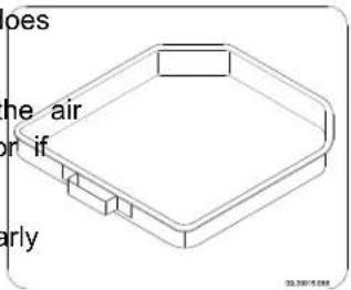
Using the cold handle glove supplied, remove the ash pan and empty it; see the next two figures.

The secondary air inlet not only supplies air to the fire but to the glass as well, so that it does not quickly become dirty.
text_image
oes he air on if early 20.2001/5.048Open the primary air inlet for the time being if the air supply by the secondary air inlet is inadequate or if you want to fan the fire.
It is better to add a small amount of logs regularly than to add many logs at the same time.
▶ Regularly adding small amounts of brown coal briquettes or anthracite coal is better than adding a large amount of brown coal briquettes or anthracite coal in one go.
Extinguishing the fire
Do not add fuel and just let the fire go out. If a fire is damped down by reducing the air supply, harmful substances will be released. For this reason, the fire should be allowed to go out naturally. Keep an eye on the fire until it has gone out. All air inlets can be closed once the fire has died completely.
natural_image
Technical line drawing of a mechanical component (no text or symbols present)- Replace the ash pan and close the door of the appliance.
Removing ash
After wood has burnt, a relatively small amount of ash is left over. This ash bed is a good insulating layer for the stove base plate and improves combustion. It is good idea to leave a thin layer of ash on the stove base plate.
After brown coal briquettes and anthracite coal have burnt, a relatively large amount of ash is left over. Remove the excess ash regularly.
Fog and mist
Solving problems
Refer to the appendix "Diagnostic diagram" to resolve any problems in using the stove.

Maintenance
Follow the maintenance instructions in this chapter to keep the stove in good condition.
Chimney
In many countries, you are required by law to have your chimney checked and maintained.
At the beginning of the heating season: have the chimney swept by an expert.
During the heating season and after the chimney pl has not been used for a long time: have the chimney checked for soot deposits.
After the heating season: seal off the chimney with a ball of paper.
Cleaning and other regular maintenance activities

Do not clean the stove when it is still warm.
Clean the exterior of the stove with a dry lint-free cloth.
You can clean the stove interior thoroughly at the end of the heating season: 5.
If necessary, first remove the fire-resistant inner plates. See the chapter "Installation" for instructions on removing and installing the inner plates.
▶ If necessary, clean the air supply ducts.
Remove the baffle plate at the top of the appliance and clean it.
Checking fire-resistant inner plates
The fire-resistant inner plates are consumables and subject to wear. Check the fire-resistant inner plate frequently and replace them when necessary.
▶ See the chapter "Installation" for instructions on removing and installing the inner plates.

The insulating vermiculite or chamotte inner plates may develop hairline cracks, but this does not affect their performance adversely.

Cast-iron inner plates last a long time if you remove frequently the ash that can accumulate behind them. If accumulated ash behind the cast-iron plate is not removed, the plate will no longer be able to dissipate the heat to the surroundings and this may cause the plate to warp or crack.

Never use the stove without the fire-resistant inner plates.
Dismantling damper and baffle plate
Both the damper and the baffle plate can be dismantled. To dismantle the baffle plate, the damper with and the damper rod must first be removed.
- Open the stove door.
- Lift the closed damper slightly and slide it above the baffle plate so that they are both free.
- Remove the damper and the damper rod from the appliance.
- Loosen the support plate by loosening the M8 nut. The support plate is located in the middle against the top plate of the appliance.
- Lift the baffle plate at the front, pull the baffle plate forward and take the baffle plate out of the appliance.
Comment: To fit the damper and the baffle plate, before starting to use the appliance, follow the above instructions in the reverse order.
Cleaning glass
Dirt clings less easily to well-cleaned glass. Proceed as follows:
- Remove dust and loose soot with a dry cloth.
-
Clean the glass with stove glass cleaner:
a. Apply stove glass cleaner to a kitchen sponge, rub down the entire glass surface and give the cleaning agent time to react.
b. Remove the dirt with a moist cloth or kitchen tissue. -
Clean the glass again with a normal glass cleaning product.

- Rub the glass clean with a dry cloth or kitchen tissue.
Do not use abrasive or aggressive products to clean the glass.
▶ Wear household gloves to protect your hands.

If the glass in the appliance is broken or cracked, it must be replaced before you can use the appliance again.

Make sure that no stove window cleaner runs between the glass and the cast-iron door.
Lubrication
Although cast-iron is slightly self-lubricating, you will still need to lubricate moving parts frequently.
Lubricate the moving parts (such as guide systems, hinge pins, latches and air slides) with heat resistant grease that is available in the specialist trade.
text_image
tis- 09.20015.067Touching-up the paint finish
Small areas of damaged paint finish can be touched up with a spraying can of special heat-resistant paint finish available from your supplier.
Checking the seal
▶ Check whether the door sealing rope is still in good Use the adjusting screws to adjust the hinge post condition and works well. The sealing rope is sub- widthwise in the appliance. ject to wear and will need to be replaced over time.
▶ Check the appliance for air leaks. Close any chinks with stove sealant.
- Tighten the two mounting bolts and check whether the door closes properly.

Allow the sealant to harden fully before lighting the stove, as any moisture in the sealant will form bubbles, resulting in a new air leak.
Adjust door
Check if the door closes properly; if necessary, adjust the hinge post; see next figure.
Appendix 1: Technical data
Model 2200 / 2210 / 2220 / 2020
| Model 2200 2210 2220 2020 | ||||
| Nominal output 8 kW 8 kW 8 kW 7 kW | ||||
| Flue connection (diameter) 150 mm 150 mm 150 mm 150 mm | ||||
| Weight | 140 kg | 175 kg | 150 kg | 130 kg |
| Recommended fuel | Wood | Wood | Wood | Wood |
| Fuel property, max. length wood | 50 cm | 50 cm | 50 cm | 40 cm |
| Electrical connection | 230 V, 50 Hz, 0.5 A | |||
| Fuel | Wood | Brown coal bri-quettes | Anthracite coal |
| Mass flow of flue gasses | 7.7 g/s | 8.9 g/s | 7.8 g/s |
| Temperature increase measured in the measuring section | 295 K | 289 K | 272 K |
| Temperature measured at appliance exit | 340 °C | - | - |
| Minimum draught | 14 Pa | 14 Pa | 14 Pa |
| CO emission (13% _2 O) | 0.10 % | 0.06 % | 0.04 % |
| NOx emission (13% _2 O) | 106 mg/Nm ^3 | - | - |
| CnHm emission (13% _2 O) | 51 mg/Nm ^3 | - | - |
| Particulate emission | 31 mg/Nm ^3 | - | - |
| Efficiency | 78.3 % | 75.4 % | 76.4 % |
Model 2500 / 2510 / 2520 / 2620
| Model 2500 2510 2520 2620 | ||||
| Nominal output 10 kW 10 kW 10 kW | 10 kW | |||
| Flue connection (diameter) 150 mm 150 mm 150 mm | 150 mm | 150 mm | ||
| Weight 150 kg 180 kg | 160 kg | 160 kg | ||
| Recommended fuel | Wood | Wood | Wood | Wood |
| Fuel property, max. length wood | 50 cm | 50 cm | 50 cm | 50 cm |
| Electrical connection | 230 V, 50 Hz, 0.5 A | |||
| Fuel | Wood | Brown coal bri-quettes | Anthracite coal |
| Mass flow of flue gasses | 9.2 g/s | 9.7 g/s | 8.1 g/s |
| Temperature increase measured in the measuring section | 264 K | 318 K | 314 K |
| Temperature measured at appliance exit | 320 °C | - | - |
| Minimum draught | 14 Pa | 14 Pa | 14 Pa |
| CO emission (13% _2 ) | 0.10 % | 0.09 % | 0.05 % |
| NOx emission (13% O_2 ) | 52 mg/Nm ^3 | - | - |
| CnHm emission (13% _2 ) | 21 mg/Nm ^3 | - | - |
| Particulate emission | 16 mg/Nm ^3 | - | - |
| Efficiency | 80.0 % | 76.4 % | 79.0 % |
Appendix 2: Connection diagrams
The codes in the diagrams below have the following meaning:
T1 thermoswitch
V1 fan
V2 fan
L1 lamp
R1 resistor
S1 2-position switch
Model 2020
text_image
V1 V2 T1 230VModel 2220, model 2520 and model 2620
text_image
V1 V2 T1 L1 N N M L2 230 V NModel 2210 and model 2510
text_image
V1 V2 L1 T1 230 V N L2 L1Model 2200 and model 2500
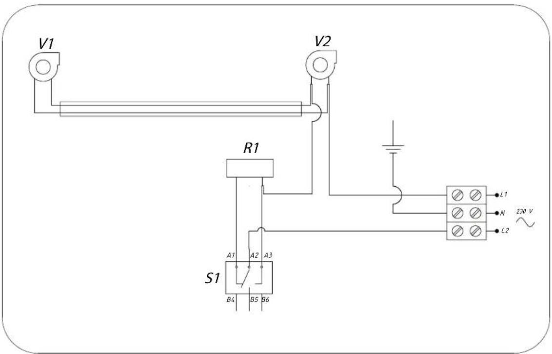
text_image
V1 R1 S1 A1 A2 A3 B4 B5 B6 V2 L1 N 230 V L2Models 2200 and 2500 are designed with two-position switches for speed control; they have no mostat function.
Appendix 3: Dimensions
2020
text_image
590 495 Dovre 440 Ø150 Ø125 75 120 430 09.20017.0442200

text_image
595 560 670 450 Ø150 200 110 Ø125 450 09.20017.0432210
text_image
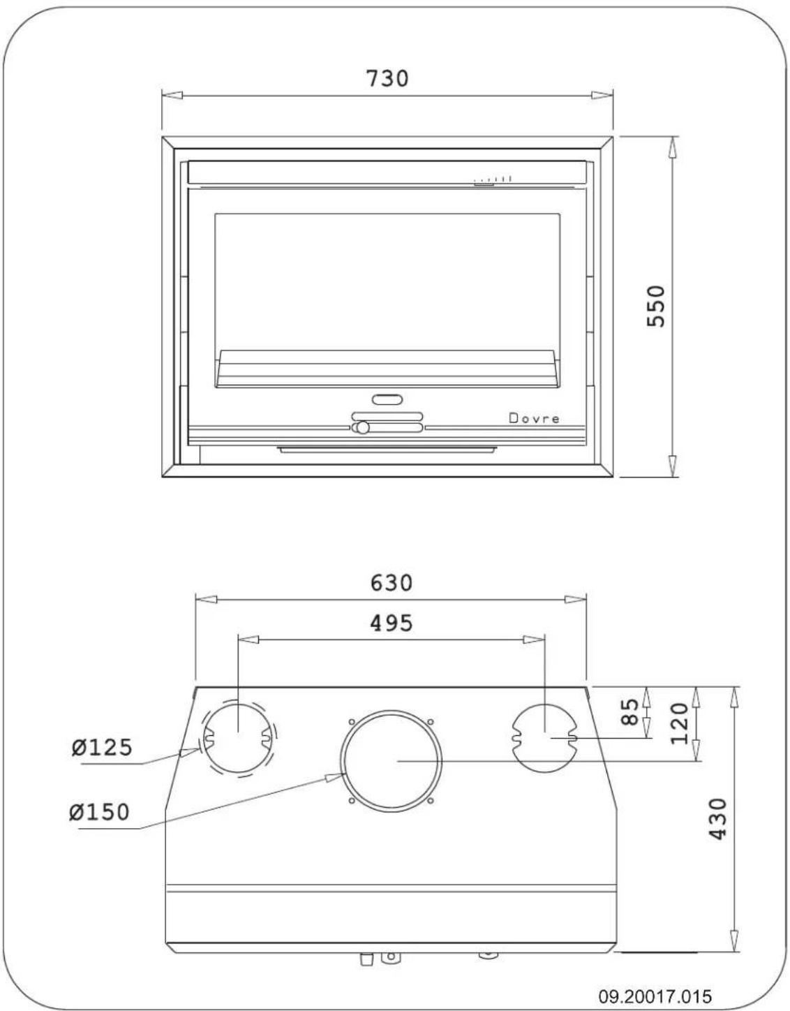
730 550 Dovre 630 495 Ø125 Ø150 85 120 430 09.20017.0152220
text_image
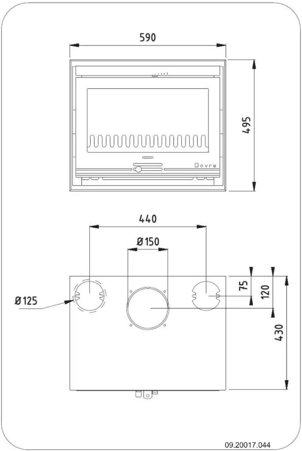
690 540 Dovre 540 Ø125 Ø150 75 120 430 09.20017.0142500
text_image
655 620 670 450 Ø150 200 110 Ø125 450 09.20017.042
2510
text_image
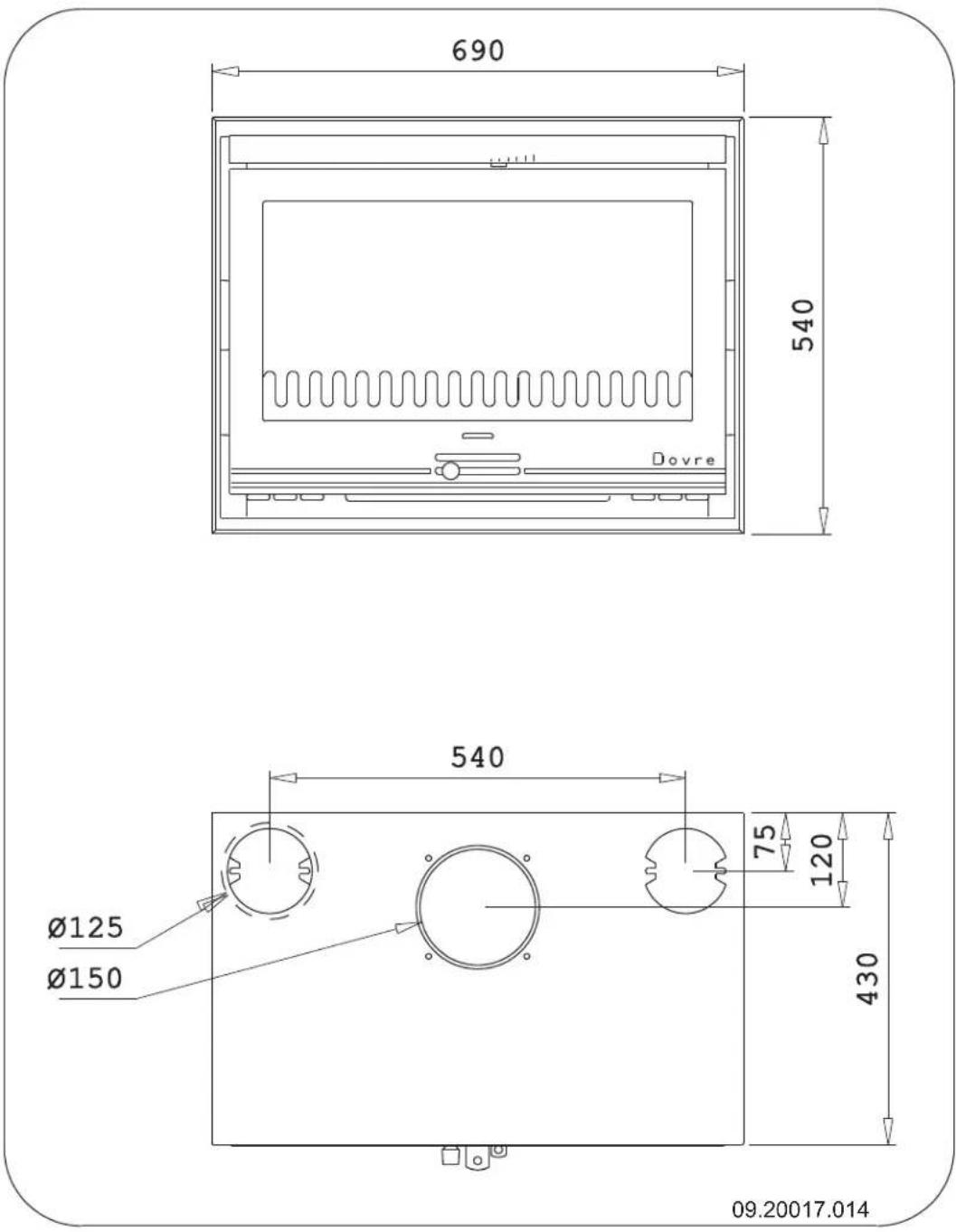
Dovre 610 730 630 495 Ø125 Ø150 85 120 430 09.20017.0162520
text_image
690 600 Dovre 540 Ø125 Ø150 75 120 430 09.20017.0122520BS
text_image
480 690 600 540 125 75 Ø125 Ø150 430 485 09.20017.0132620SC
text_image
690 600 540 75 120 450 430 Ø25 Ø150 09-20020-179Appendix 4: Distance from combustible material
Minimum ventilation outside the radiation range
text_image
MIN 1 CM MIN 1 CM 09.20015.048Dimensions of fireproof floor plate in centimetres
text_image
99.20015.046 V S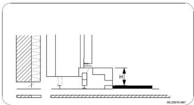
text_image
09.20015.047Minimum dimensions of fireproof floor plate
$$ V > H + 3 0 > 6 0 $$
$$ S > H + 2 0 > 4 0 $$
Appendix 5: Diagnosis diagram
| Problem | ||||||
| ● | Wood will not stay lit | |||||
| ● | Gives off insufficient heat | |||||
| ● | Smoke emissions into the room when adding wood | |||||
| ● | Fire in stove is too intense, is hard to adjust | |||||
| ● | Deposit on the glass | |||||
| possible cause possible | solution | |||||
| ● | ● | ● | ● | Insufficient draught | A cold flue usually failsto create sufficient draught. Follow the instructions for starting a fire in the 'Use' section; open a window. | |
| ● | ● | ● | ● | Wood too damp Use wood with no more than 20% moisture. | ||
| ● | ● | ● | ● | Logs too large | Use small pieces of kindling. Use split logs no larger than 30 cm in circumference. | |
| ● | ● | ● | ● | ● | Wood stacked incorrectly | Stack the logs in a way that allows adequate air flow between the logs (open stacking, see "Burning wood") |
| ● | ● | ● | ● | Chimney does not work properly | Check whether the chimney meets the requirements: at least 4 metres high, correct diameter, well-insulated, smooth inside, not too many bends, no obstructions in chimney (bird'snest, too much soot deposit), hermetically tight (no chinks). | |
| ● | ● | ● | ● | Chimney stack incorrect Sufficiently high above the roof, no obstacles in the vicinity | ||
| ● | ● | ● | ● | ● | Air inlets set incorrectly Open the air | inlets completely. |
| ● | ● | ● | ● | Stove connected to the chimney incor-rectly | Connection should be hermetically tight. | |
| ● | ● | ● | ● | Vacuum in area in which the stove is installed | Switch off extraction systems. | |
| ● | ● | ● | ● | Insufficient supply of fresh air | Provide an adequate air supply; if necessary use outside air con- nection. | |
| ● | ● | ● | ● | Bad weather? Inversion (reversed air flow in chimney) we recommend you don't use the appliance in the case of inversion. because of a high outside temperature if required, installan extra hood on the flue to increase the draught. extreme wind speeds | ||
| ● | Draught in the living room | Avoid draught in the living room, do not place the appliance near a door or heating air ducts. | ||||
| ● | Flames touch the glass | Make sure the wood is not positioned too close to the glass. Slide the primary air inlet cover closer to the "Closed" position. | ||||
| ● | Stove is leaking air Check the door seals and stove joints. | |||||
Index
A
Adding
anthracite coal 20 brown coal briquettes 20
Adding fuel.20
Adding wood
smoking stove 38
Air combustion control.19.
Air control.19
Air inlets..17.
Air leak 22
Air supply for fire.... 20
Anthracite coal 17
ash 20
Ash pan
open 20
Ashes
remove 20
B
Baffle plate
fit 21
Bearing capacity of floor.... 9
Brown coal
ash 19
burning 19
Brown coal briquettes.... 16
Burning
adding fuel.... 19
anthracite coal 19
appliance is hard to adjust.... 38
brown coal briquettes 19
fire is too intense.... 38
insufficient heat 38
Burning wood.... 18
add fuel 20
adding logs.... 18
insufficient heat 20
C
Carpet 9
Cast iron
fire resistant 11
inner plates.... 11
Chimney
height 9
sweep 21
Chinks in appliance.... 22
Clean
glass 21
Cleaning
appliance 21
Coal
ash content 17
Combustible material
distance from.... 37
Connecting
dimensions 28
Continuous use.... 11
Control air supply.... 20
Convection
drawing off..11,.14....
other areas 11, 14
convection hear.... 11, 14
Convection space
cover plate.... 14
Cover on flue 9
Cover plate
convection space....14
Creosote 19
D
Damp wood.... 16
Damper
fit 21
Decorative surround
fit 15
Dimensions 28
Door
adjust 22
change swing direction.... 11
closing 22
sealing rope 22
Draught 23-24
Drawing off.... 11, 14
Drying wood 16
E
Efficiency 5,7,23-24
External air supply connecting to 13....
F
Fan electric .11..... thermostatic .11....
Filling height 18
Finishing decorative frame 15
Finishing coat, maintenance 22....
Fire extinguishing .20..... lighting .17....
Fire-resistant inner plates maintenance 21
Fire going out 20....
Fire safety distance from combustible material.37.... floor .9.... furniture....9 walls....9
Fireproof inner plates warning 16
Floors bearing capacity....9 fire safety....9
Flue connecting to.13..... connection diameter.... 23-24 maintenance .21.... requirements.... 8
Flue gas temperature 5, 7
Flue gasses mass flow 23-24
Fog, do not burn wood.... 20
Frame fit 15
Fuel adding 20
adding wood 18
anthracite coal 16-17
brown coal 16
brown coal briquettes.... 16
necessary amount 20
suitable 16
unsuitable 16
wood 16
G
Glass clean ....21 deposit 38
H
Heat, insufficient 20, 38
Hinge set 22
Hood on the flue....9
|
Inner plates cast iron 11
Installing dimensions 28
K
Kindled fire 17
Kindling 38
L
Lighting 17
Lubricant 22
Lubricate 22
M
Maintenance chimney 21 clean glass 21 cleaning the appliance 2 fire-resistant inner plates 2 lubrication 22 sealing 22
measuring section 23-24
Mist, do not burn wood.... 20
N
Nominal output 20, 23-24
0
Open ash pan....20
P
Paint finish 16
Particulate emission 23-24
Prevent a chimney fire..19....
Primary air inlet 17.
R
Removing ash 20
brown coal.19....
s
Screens
clean 21
deposit .38....
Sealing rope for door.22
Secondary air inlet 17
Smoke
on first use.... 16
Smoke emissions into the room 8
Smoking stove.... 38
Softwood 16
Solving problems.... 20, 38
Stacking logs 18
Storing wood 16
Stove window cleaner 21
Suitable fuel 16
Sweep chimney 21
Swing direction
change 11
T
Tar 19
Temperature 23-24
Temperature increase 23-24
U
Unsuitable fuel 16
v
Ventilation 9
rule of thumb....9
Ventilation louvre 9
W
Walls
fire safety....9
Warning
chimney fire.... 16, 19
chimney fires 8
fireproof inner plates 16
flammable materials 8
glass broken or cracked 22
glass is broken or cracked 8
hot surface....8
requirements 8
stove window cleaner.... 22
terms and conditions for insurance 8
ventilation 8-9
Weather conditions, do not burn wood.... 20
Weight 23-24
Wood 16
damp 16
drying 16
right sort.... 16
storing 16
will not stay lit 38
Table des matières
Introduction 3
natural_image
Technical line drawing of a mechanical component (no text or symbols)natural_image
Technical line drawing of a mechanical component with threaded shaft and flange (no text or symbols)natural_image
Diagram of a mechanical device with rotational arrows indicating motion, no text or symbols presentnatural_image
Technical line drawing of a mechanical housing or enclosure with mounting flanges and internal components (no text or symbols)
natural_image
Technical line drawing of a mechanical device with mounting brackets and internal components (no text or symbols)natural_image
Technical line drawing of a corner shelf assembly with mounting fixtures and a hook (no text or symbols)natural_image
Technical line drawing of a mechanical assembly with no visible text or symbolsnatural_image
Technical line drawing of a mechanical bracket with a labeled component 'A' (no text or symbols beyond label)natural_image
Pure technical diagram of a rectangular frame with arrows indicating upward movement, no text or symbols presentnatural_image
Technical line drawing of a mechanical device with mounting holes and internal components (no text or symbols)Finition
natural_image
Illustration of layered geological strata with a central peak and grid pattern (no text or symbols)natural_image
Illustration of a broken stone or mineral fragment with visible grain patterns (no text or symbols)natural_image
Illustration of fragmented, irregularly shaped objects with grid patterns, no text or symbols presentnatural_image
Line drawing of a rectangular container with no text or symbols

natural_image
Isometric line drawing of a rectangular tray or container with internal compartments (no text or symbols)Extinction du foyer
natural_image
Technical line drawing of a mechanical component (no text or symbols)Décendrage
text_image
V1 V2 T1 230Vtext_image
V1 V2 T1 L1 L2 N 230 Vtext_image
V1 R1 S1 A1 A2 A3 B4 B5 B6 V2 L1 N 230 V L2raccordement .15....
Convection
espaces externes.... 12, 15
soutirage 12, 15
natural_image
Technical line drawing of a mechanical component (no text or symbols)natural_image
Technical line drawing of a mechanical component with threaded shaft and flange (no text or symbols)natural_image
Diagram of a mechanical device with rotational arrows indicating motion, no text or symbols presentnatural_image
Technical line drawing of a microwave oven with mounting brackets and internal components (no text or symbols)natural_image
Technical line drawing of a mechanical device with mounting holes and internal components (no text or symbols)natural_image
Technical line drawing of a structural support bracket with mounting feet and internal components (no text or symbols)natural_image
Technical line drawing of two structural beams with a central bracket and a labeled connection point (A), no text or symbols present.natural_image
Pure technical diagram of a rectangular frame with an upward arrow, no text or symbols presentnatural_image
Technical line drawing of a mechanical assembly with no visible text or symbolsnatural_image
Technical line drawing of a mechanical device with mounting brackets and internal components (no text or symbols)Ausführung
natural_image
Illustration of layered geological strata with no visible text or symbolsnatural_image
Technical line drawing of a door frame with adjustment knob and hanging clip, no text or symbols present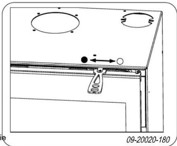
natural_image
Technical diagram of a mechanical assembly with mounting holes and a hanging clamp (no text or symbols)• = Geschlossen ○ = Offen
Heizen mit Holz
natural_image
Illustration of a textured, folded object with no visible text or symbolsnatural_image
Illustration of fragmented stone or mineral fragments with visible grain patterns (no text or symbols)natural_image
Line drawing of a rectangular container or tray with no text or symbols
natural_image
Isometric line drawing of a rectangular tray or container with internal compartments (no text or symbols)Löschen des Feuers
natural_image
Technical line drawing of a mechanical component (no text or symbols)text_image
V1 V2 T1 230Vtext_image
V1 V2 T1 L1 L2 N 230 Vtext_image
V1 V2 Z30 V N L2 L1 T1 L1text_image
V1 R1 S1 A1 A2 A3 B4 B5 B6 V2 L1 N 230 V L2Schornsteinbrand 8, 17, 20
Ventilation 8
Vorschriften 8
Wartung
Abdichtung 23
natural_image
Technical line drawing of a mechanical component (no text or symbols)natural_image
Technical line drawing of a mechanical component with threaded shaft and flange (no text or symbols)natural_image
Diagram of a mechanical device with rotational arrows indicating motion, no text or symbols presentnatural_image
Technical line drawing of a mechanical device with mounting brackets and internal components (no text or symbols)natural_image
Technical line drawing of a microwave oven with mounting holes and internal components (no text or symbols)natural_image
Technical line drawing of a corner shelf assembly with mounting fixtures and a hook (no text or symbols)natural_image
Technical line drawing of a mechanical assembly with no visible text or symbolsnatural_image
Technical line drawing of a mechanical bracket with a labeled component 'A' (no text or symbols beyond label)natural_image
Pure technical diagram of a rectangular frame with arrows indicating upward motion, no text or symbols presentnatural_image
Technical line drawing of a mechanical device with mounting holes and internal components (no text or symbols)Acabado
natural_image
Illustration of layered geological strata with no visible text or symbolsnatural_image
Technical diagram of a door frame with a spring scale and directional arrows indicating movement (no text or symbols)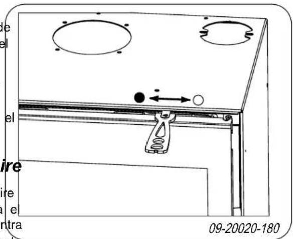
text_image
e el el ire re e ntra 09-20020-180- = Cerrada
- = Abierta
Alimentar con leña
natural_image
Illustration of a broken stone or mineral sample with visible grain patterns (no text or symbols)natural_image
Illustration of a broken stone or mineral sample with visible grain patterns and texture (no text or symbols)natural_image
Technical line drawing of a mechanical component (no text or symbols)natural_image
Line drawing of a rectangular tray or container with a rectangular slot on top (no text or symbols)text_image
V1 V2 T1 230Vtext_image
V1 V2 T1 L1 L2 N 230 Vtext_image
V1 V2 Z30 V N L2 L1 T1 L1text_image
V1 R1 S1 A1 A2 A3 B4 B5 B6 V2 L1 N 230 V L2natural_image
Technical line drawing of a mechanical component (no text or symbols)natural_image
Technical line drawing of a mechanical component with threaded shaft and flange (no text or symbols)natural_image
Diagram of a mechanical device with rotational arrows indicating motion, no text or symbols presentnatural_image
Technical line drawing of a mechanical device with mounting holes and internal components (no text or symbols)natural_image
Technical line drawing of a mechanical device with mounting holes and internal components (no text or symbols)text_image
09.20015.057 A B C D E P F G H I N J K O 3 cm L Mnatural_image
Technical line drawing of a corner bracket with mounting fixtures and a wall-mounted component (no text or symbols)natural_image
Technical line drawing of two structural beams with a central bracket and a labeled connection point (A), no text or symbols present.natural_image
Pure technical line drawing of a rectangular frame with an upward arrow, no text or symbols presentnatural_image
Technical line drawing of a mechanical assembly with no visible text or symbolsnatural_image
Technical line drawing of a mechanical device with mounting brackets and internal components (no text or symbols)Completamento
natural_image
Illustration of layered geological strata with no visible text or symbolsnatural_image
Technical line drawing of a door frame with a spring scale and directional arrows indicating movement (no text or symbols)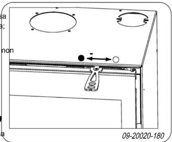
text_image
a ; non 09-20020-180◦ = Aperta
natural_image
Illustration of a broken stone or mineral sample with visible grain patterns (no text or symbols)natural_image
Illustration of fragmented, irregularly shaped objects with grid patterns, no text or symbols presentnatural_image
Line drawing of a rectangular container or tray with no text or symbols

natural_image
Isometric line drawing of a rectangular tray or container with a rectangular slot on top (no text or symbols)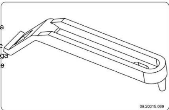
natural_image
Technical line drawing of a mechanical component with labeled parts (a, e, ga, e) and no readable text or symbols beyond labelsFoschia e nebbia
text_image
V1 V2 T1 230VModello 2220, modello 2520 e modello 2620
text_image
V1 V2 T1 L1 L2 N 230 VModello 2210 e modello 2510