2180CBBS - Fireplace DOVRE - Free user manual and instructions
Find the device manual for free 2180CBBS DOVRE in PDF.
| Product type | Built-in fireplace |
| Brand | Dovre |
| Model | 2180CBBS |
| Nominal power | 15 kW |
| Connection diameter | 200 mm |
| Weight | 190 kg |
| Fuel | Wood (logs up to 50 cm) |
| Efficiency | 76% |
| Minimum draft | 12 Pa |
| CO emissions (13% O2) | 0.10% |
| NOx emissions (13% O2) | 97 mg/Nm³ |
| CnHm emissions (13% O2) | 96 mg/Nm³ |
| Dust emissions | 22 mg/Nm³ |
| Material | Cast iron and steel |
| Glass type | Panoramic glass (model 2180CBGD) or standard |
| Regular maintenance | Cleaning the glass, lubricating moving parts |
| Chimney sweeping | At the beginning of the heating season and during |
| Safety | Minimum distance to combustible materials (see appendix) |
| Wear parts | Refractory plates, sealing gasket |
| Installation | Connection to a chimney flue, room ventilation |
Frequently Asked Questions - 2180CBBS DOVRE
User questions about 2180CBBS DOVRE
0 question about this device. Answer the ones you know or ask your own.
Ask a new question about this device
Download the instructions for your Fireplace in PDF format for free! Find your manual 2180CBBS - DOVRE and take your electronic device back in hand. On this page are published all the documents necessary for the use of your device. 2180CBBS by DOVRE.
USER MANUAL 2180CBBS DOVRE
Inbouwaard 2180CBGD, 2180CBC 2180CBS, 2180CBBS
Inhoudsopgave
Inleiding.3
Declaration of conformity 3
Safety 4
Installation requirements..4
General 4
Flue or chimney 4
Ventilation of the area 5
Floors and walls 6
Product description 6
Installation 7
Preparation 7
Fitting the outside air intake.duct 11
Building into a new hearth. 11
Use. 14
First use. 14
Fuel 14
Lighting 14
Burning wood 15
Controlling the air 15
Extinguishing the fire 16
Removing ashes 16
Fog and mist 17
Solving problems 17
Maintenance 17
Chimney 17
Cleaning and other regular maintenance.
activities. 17
Panoramic lifting door: model 2180CBGD 18
Appendix 1: Technical Data. 22
Appendix 2:Measurements. 23
Appendix 3: Distance from combustible
material 26
Appendix 4: Diagnostic diagram 27
Index 28
Introduction
Dear user,
In buying this DOVRE heating appliance, you have chosen a high quality product. This product is part of a new generation of energy saving and environmentally friendly heating appliances. These appliances make optimal use of convection heat as well as thermal radiation (radiant heat).
- Your DOVRE appliance has been manufactured with state-of-the-art production equipment. In the unlikely event of a malfunction, you can always rely on DOVRE for support and service.
The appliance is not to be modified; always use original parts.
The appliance is intended for use in a living room. It must be connected hermetically to a well-functioning chimney.
We advise you to let an authorized and competed 2180CBBS are manufactured in accordance with EN installation company install the appliance. 13229.
DOVRE cannot be held liable for any problems or damage resulting from incorrect installation.
Observe the following safety rules when installing and using the appliance.
In this manual, you can read how the DOVRE heating appliance can be installed, used and maintained T. C safely. Should you require additional information or technical data, or should you experience an installation problem, please contact your supplier first.
© 2012 DOVRE NV
Due to continuous product improvement, specifications of the appliance supplied may vary from the description in this brochure without prior notice.
Please note: All safety regulations must be complied with strictly.
Carefully read the instructions for installation, use and maintenance before you start using the appliance.
The appliance must be installed in accordance with the laws and requirements of your country.
All local regulations and the regulations relating to national and European standards must be observed when installing the appliance.
Read the instructions for installation, use and maintenance supplied with the appliance.
It is preferable to have the appliance installed by an authorized and competent installation company. They will be aware of the applicable regulations and requirements.
The appliance is designed for heating purposes. All surfaces, including the glass and the connecting tube, can get very hot (over 100^ ! For operation, use a so-called "cold hand" or an oven glove.
Don't place any curtains, clothes, laundry or other combustible materials on or near the appliance.
Don't use flammable or explosive substances near the appliance when it is in use.
Avoid a chimney fire by having the chimney swept regularly. Never burn wood with an open door.
In the case of a chimney fire: close all air of the appliance and alert the fire brigade.
If the glass in the appliance is broken or cracked, it must be replaced before you can use the appliance again.
Make sure there is adequate ventilation in the room where the appliance is installed. The combustion will be incomplete in case of insufficient ventilation, which results in toxic gases being produced and spread through the room. See the chapter "Installation requirements" for more information on ventilation.
Installation requirements
General
The appliance must be connected tightly to a well-functioning chimney.
For the connection measurements: see the appendix "Technical data".
Ask the fire brigade and/or your insurance company about any specific requirements and regulations.
Flue or chimney
The flue or chimney is needed for:
Disposing of the combustion gases through natural draught.
The warm air in the flue or chimney is lighter than the outside air so it rises.
The intake of air, needed for the combustion of fuel in the appliance.
open A poorly functioning flue or chimney can cause smokers to escape into the room when the door is opened.
mamage caused by smoke emissions into the room is not covered by the warranty.
Do not connect multiple appliances (such as a boiler for central heating) to the same flue, unless local or national regulations allow this.
Ask your installer for advice regarding the flue. Refer to the European norm EN13384 for a correct calculation for the flue.
The flue must satisfy the following requirements:
The flue or chimney must be made of fire resistance material, preferably ceramics or stainless steel.
The flue or chimney must be airtight and well cleaned and guarantee sufficient draught.
i
A draught/vaccuum of 15 - 20 Pa during normal operation is ideal.
Starting from the flue spigot, the flue must run a vertically as possible. Changes in direction and horizontal pieces disrupt the outward flow of combustion gases and may cause the deposit of soot.
The interior measurements should not be too big prevent the combustion gases from cooling down too much, thereby reducing the draught.
The flue or chimney must ideally have the same diameter as the connection collar.
i
For the nominal diameter: see the appendix "Technical data". If the smoke channel is well insulated, the diameter may be slightly bigger (up to 2x the section of the connection collar)
The section (area) of the smoke channel must constant. Wider segments and (in particular) narrower segments disrupt the outward flow of combustion gases.
- When using a cover plate or exhaust hood: measure that the cover does not restrict the flue out and that the cap does not impede the outward of combustion gases.
The chimney must end in a zone that is not affected by surrounding buildings, adjacent trees, other obstacles.
The chimney part outside the house must be insulated.
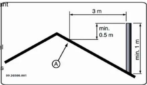
The chimney must be at least 4 metres high.
As a rule of thumb: 60cm above the ridge of the roof.
If the ridge of the roof is more than 3 metres away from the flue: stick to the measurements in the following figure. A = the highest point of the roof within a distance of 3 metres.
To good combustion, the appliance needs air (oxygen). That air is supplied via adjustable air inlets from the area where the appliance is installed.
The combustion will be incomplete in case of insufficient ventilation, which results in toxic gases being produced and spread through the area.
As a rule of thumb, the air supply should be 5.5cm^2 /kW Extra ventilation is needed when:
The appliance is in an area that is well insulated.
There is mechanical ventilation, for example a central extraction system or an extraction hood in an open kitchen.
You can provide extra ventilation by having a low ventilation louvre installed in the outside wall.
Make sure that other air consuming appliances (such as tumble-driers, other heating appliances or a bath or fan) have their own supply of outside air, or are switched off when you use the appliance.
i
You can also connect the appliance to a supply of outside air. For this purpose, a connecting kit has been included. Extra ventilation is not needed in that case.
Floors and walls
The floor on which the appliance is placed must have sufficient bearing capacity. For the weight of the appliance, see the appendix "Technical data".

There may not be any electrical wires in the floor below the appliance and in the walls around it.

All flammable materials must be removed from under the appliance or protected by at least a cm concrete slab.

Flammable walls bordering the appliance must be protected by at least a 10 cm stone wall 5 cm insulation.

Protect non-flammable walls bordering the appliance with at least 2.5cm insulation to avoid cracking.

Protect a flammable floor from heat radiation and falling ash by means of a fireproof protective plate. See the appendix "Distance from combustible material".

Keep enough distance between the appliance and combustible materials such as furniture.

Ensure sufficient ventilation around flammable materials such as a mantelpiece. See appendix "Distance from combustible material".

Carpets and rugs must be at least 80 cm a from the fire.

Do not place any flammable materials within 50 cm of any convection outlets.
Product description
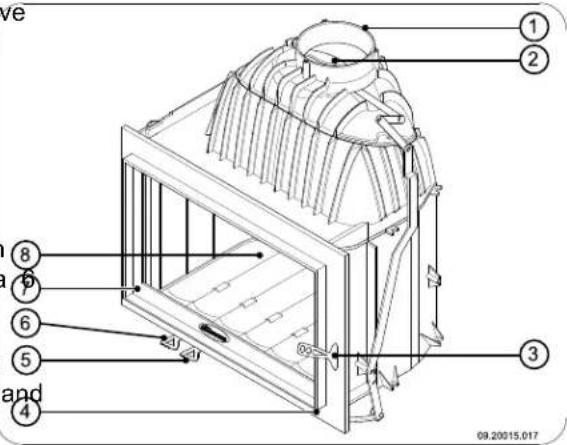
- Connection collar
- Damper
- Latch
- Damper operation
- Primary air slide
- Secondary air slide
- Door
- Bottom of the fire compartment
Features of the appliance
The appliance is fitted with a removable fire plate, log retainer and fire plate.

Cast iron inner plates protect the combustion chamber and dissipate heat to the environment.
The appliance comes standard with a connection kit for the outside air supply.
The appliance has a connection collar which can take a vertical connection as well as a 45^ connection.
The appliance is supplied with a separate handle (A), the so-called 'cold hand', for opening the door; see next figure.
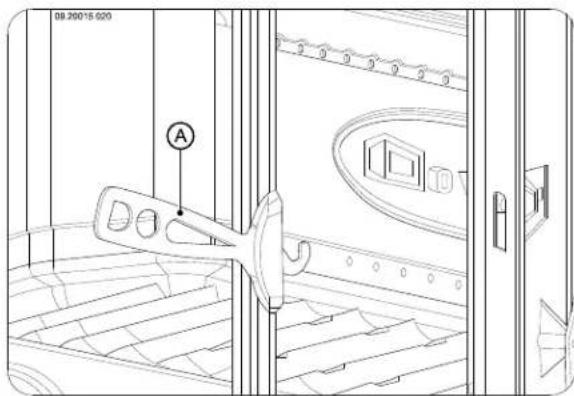
The appliance has a removable ashpan. Use the cold hand to remove it.
Supplementary feature model 2180CBGD
The appliance has a flat, panoramic lifting door. The guiding system of the door can be removed.
The appliance is supplied with a separate handle, the so-called 'cold hand', for opening the door; next figure.
Installation
Preparation
- Please check the appliance for damage caused during transport or any damage or defects immediately after delivery.
If you detect damage caused during transport or any other damage or defects, do not use the appliance and notify the supplier. - Remove the removable parts (baffle plate, fire compartment, fire basket, ash removal port and ash pan) from the appliance before you start installing the appliance.
i By removing removable parts, it is easier to move the appliance and to avoid damage.
Note the location of those removable parts, so that you have no difficulties in installing the parts in the right place later on.
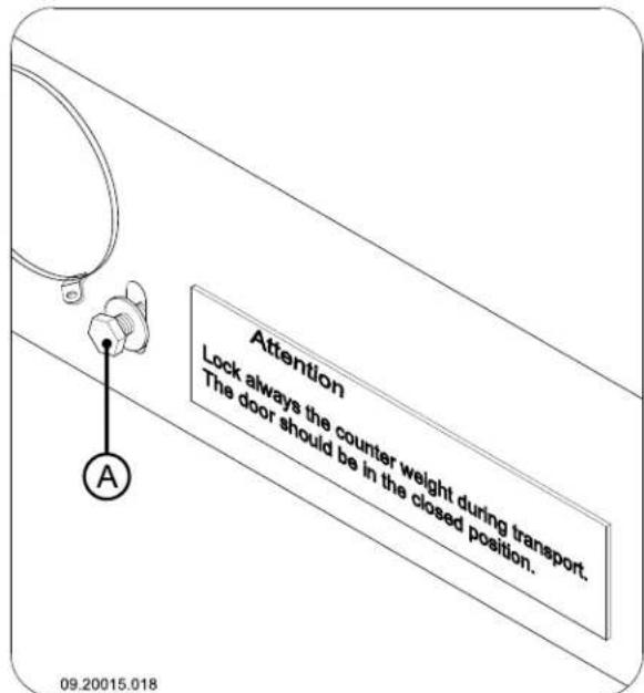
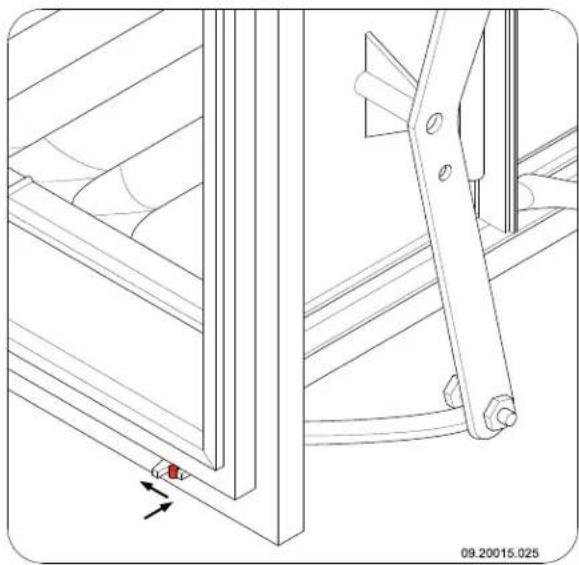
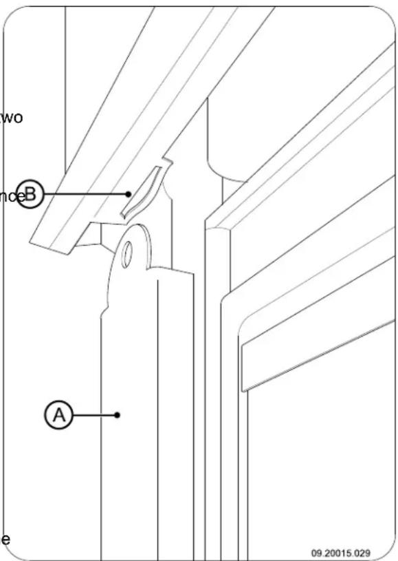
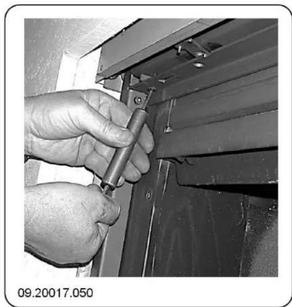
Note: In model 2180CBGD the counterweight must first be unblocked and the door must be unlocked. Follow the instructions below.
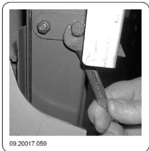
- Unblock the counterweight by removing the two bolts (A); see next figure.
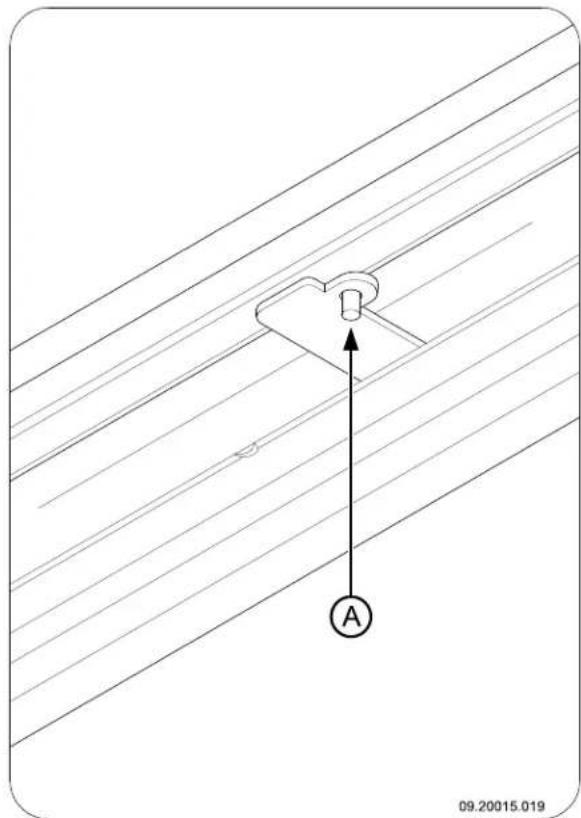
- Unlock the door by turning the two locks above the Open the door of the appliance with the cold door inward; see next figure. handle.

During transport both the door and the counterweight must be blocked.
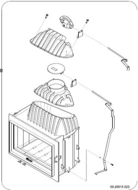
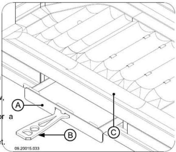
Dismantling baffle plate
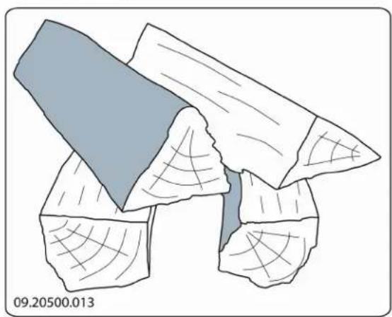
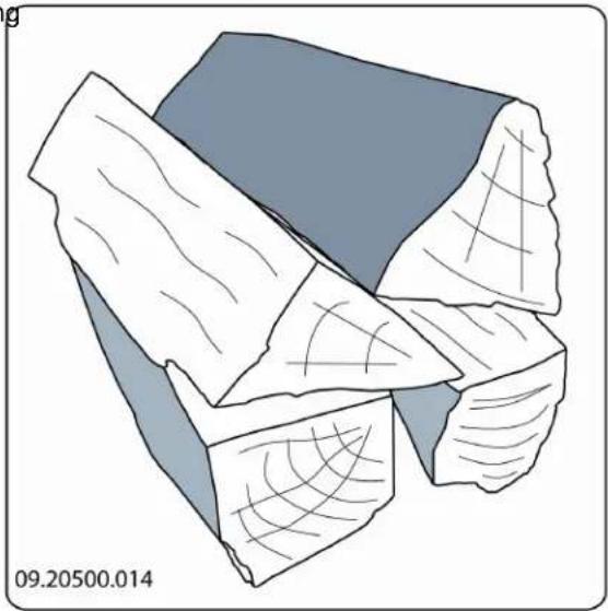
The baffle plate consists of two parts (A) and (B); next figure.
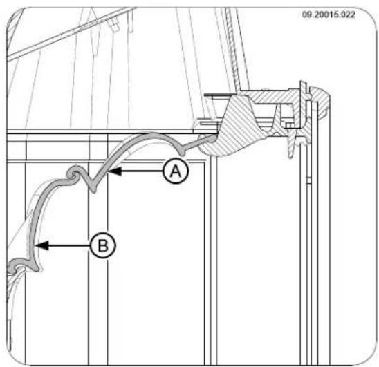

- Lift part (A) from the projections on the front side and then from part (B).
- Tilt part B from the ridge at the back.
- Take both parts out of the appliance through the door.
Note: To fit the baffle plate, follow the steps set out above in the reverse order.
Adjusting the damper position
The appliance fitted with a damper operated by a damper rod. The position of the damper regulates the efficiency of the stove: the more accurately the damper can be adjusted, the higher the efficiency.
When the door is opened and closed, the damper is opened and closes by means of the damper rod. The position of the damper depends on the draught in the chimney. When the door closes, the damper is automatically moved into the right position.
In model 2180CBGD the damper rod must be pushed in with the cold hand (A); see next figure.
When the door is closed, the damper can be opened by pushing the damper rod in a little and then moving it to the left; see next figure.
The position of the damper can be adjusted.
- Loosen the adjusting screw (A) as well a the bolt (B); see next figure.
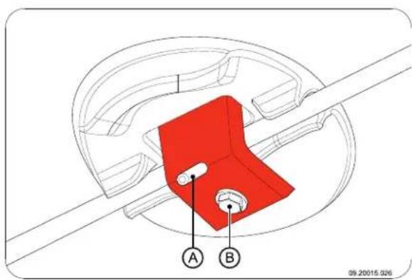
2. Turn the damper into the desired position relative to the damper rod; see next figure.
3. Tighten bolt (B) and then the adjusting screw (A) to fasten the damper to the damper rod.
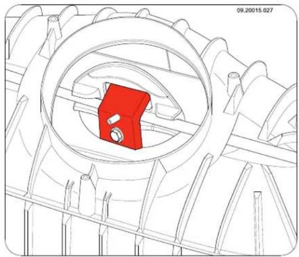
Changing the direction of the belt connection collar
If you want to use a 45^ connection instead of a vertical connection, for example because it simplifies connection to an existing flue gas duct, you have to rotate the connection collar 180^ ; see the next figure.
- Loosen the connection between the damper and the damper rod by loosening the connecting screw.
- Loosen the connection between the connection collar and the smoke dome by unscrewing the M8 nuts. The damper rod now comes off the appliance.
- Turn out the screws at the bottom of the applian whereby the damper rod is fastened to the appliance.
- remove the damper and the damper rod.

Take care not to drop the damper into the appliance when removing the damper rod.
- Lift the connection collar from the two bolts.
- Rotate the connection collar 180^ and put the connection collar back onto the smoke dome.
- Put back the damper and the damper rod and tighten the screw whereby the damper rod is fastened to the appliance.
- Connect the connection collar to the smoke dome by tightening the two M8 nuts.
- Use stove sealant as a seal between the connection collar and the smoke dome.

The stove sealant is not supplied with the appliance.
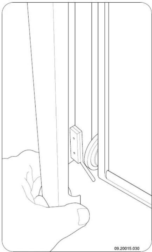
- Push the bottom of the side panel against the appliance. The panel is kept in position by a magnet; see next figure.
Fitting the side panels (model 2180CBGD only)
Model 2180CBGD is supplied with two side panels to cover the runners of the guiding system on the left and the right sides.
- Put the top of the side panel (A) into the slot (B) at the top of the appliance; see next figure.
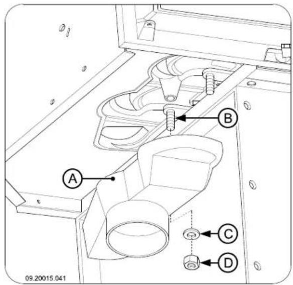
of the hole).
- Fit the air intake duct airtight to the wall.
- Fit the connection collar (A) to the M6 stud (B) using the nut (D) and the lock washer (C); see next figure.

Building into a new hearth
The stove is installed in two stages:
Placing and connecting the stove
Fitting the outside air intake duct
Building up the hearth around the stove.
Placing and connecting the stove
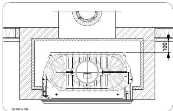
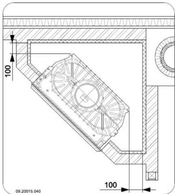
If the appliance is installed in a room without sufficient Put the appliance at the right height and level it. ventilation, you can install the connecting kit on the appliance for the supply of outside air. 2. Check that there is a clearance of 100mm
The air supply tube has a diameter of 100~mm . If installing a smooth tube, it may be no longer than 12 m. If accessories such as bends are used, the maximum length (12 m) must be reduced by 1 m for each accessory used.
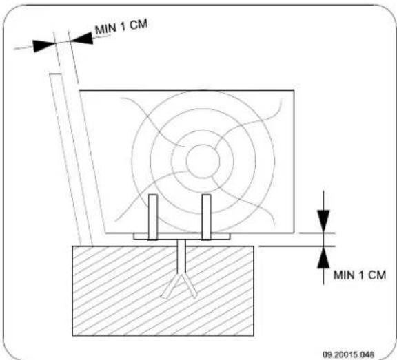
- Check that there is a clearance of 100mm between the existing walls, which must have the necessary insulation (see chapter "Installation 12 Conditions"), and the back of the appliance; see the next two figures.
Outside air intake duct through the wall or the floor and the connection collar
- Make a hole in the wall or the floor (refer to Appendix 2, "Dimensions" for a suitable position

3. Connect the appliance airtight to the flue (chimney).
4. Check the draught in the flue and the seal of the Outside air supply through the floor connection on the flue gas duct by making a small, intense trial fire with newspaper and dry, small When building the hearth, follow kindling. instructions for the convection sp

In the case of new masonry, wait until the masonry has dried sufficiently.
- In the case of connection to outside air: connect the outside air supply to the connector you have fitted to the appliance.
Structure of the hearth
Inside the hearth you provide space for convection. In air this space the air must be able to move freely. It must be possible for air to be sucked in for combustion, and
the air heated by the stove (the convection air) must be able to flow freely into the space to be heated; see next figure.
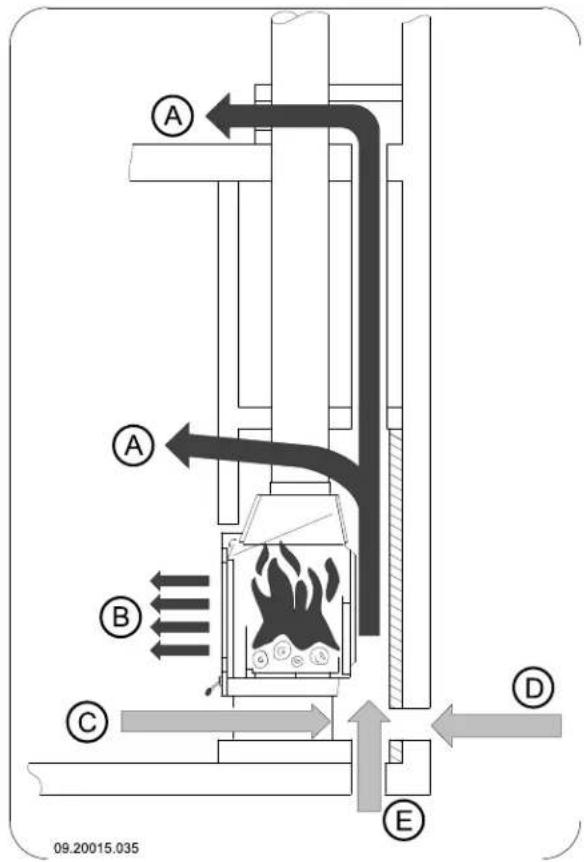
A Convection air current
B Radiated heat
C Air supply from the room to be heated
D Outside air supply through the wall
Outside air supply through the floor
mall,
When building the hearth, follow these
instructions for the convection space:
The top of the convection space must be closed airtight by means of a cover plate of incombustible and heat-resistant material.
The cover plate must be level and placed at least 30~cm below the flue opening in the ceiling.
Air inlet grates must be fitted at the bottom of the hearth to allow ambient air to flow in. The minimum Inair inlet opening is 250^2 cft the space is not
sufficiently ventilated, you must provide for outside. Make an opening above the cover plate in order to air to be allowed in by means of the outside air prevent any pressure build-up.
connection kit or an optional adjustable damper.

Air outlet grates must be fitted at the top of hearth and just below the cover plate. The minimum air outlet opening is 500 cm

The inlet and outlet grates are available as options.

Do not use combustible material in the convection space, and avoid the effect of thermal bridging when using materials that conduct heat.
Follow the instructions below when building hearth:
- Build the base of the hearth and fit the air inlet grates into the masonry.

You can place the air inlet grates on all sides of the base.

Make sure the door of the appliance can swing freely over the hearth floor.
- Build the hearth up to the smoke dome.

Ensure that a clearance of 2mm is maintained between the stove and the masonry to accommodate the thermal expansion of the stove.
- The inside of the convection space may, if desired, be cladded with reflective, insulating material.

Additional cladding of the convection space prevents unnecessary thermal radiation towards outer walls and/or adjacent rooms. It also prevents damage to the hearth wall insulation.
- Build the rest of the hearth up to the flue gas in the ceiling.

The masonry may not rest on the stove. support such as a steel beam. Leave a clearance of at least 3mm between the support and the appliance.

A Chimney (flue)
B Seal
C Cover plate
D Insulation 10 cm
E Fireproof wall min. 10 cm (e.g. cellular concrete)
F Combustible wall
G Convection space
H Fireproof ceiling
PleCombustible ceiling
J Convection air outlet
L. Fireproof floor
M Combustible floor
N Opening to prevent pressure build-up
O Connection pipe
- Put the air outlet grates under the cover plate.
Finishing
- Put all dismantled parts back into the appliance in their correct places.
- Ensure that the newly built hearth is dry enough before firing the stove.
Never light a fire in the appliance without the fireproof inner plates.
The appliance is now ready for use.
Use
First use
When you use the appliance for the first time, make an intense fire and keep it going for a good few hours. This will cure the heat-resistant paint finish. This may result in some smoke and odours. You could open windows and doors for a while in the area where the appliance is located.
Fuel
This appliance is only suitable for the burning of natural wood; sawn and chopped wood that is sufficiently dry.
Do not use other fuels, as they can lead to serious damage to the appliance. 2.
You are not allowed to use the following fuels, as the pollute the environment and because they heavily so all the appliance and flue, which may lead to a chimney fire:
Treated wood, such as scrap wood, painted wood, impregnated wood, preserved wood, plywood and chipboard.
Plastics, scrap paper and domestic waste.
Wood
Hardwood, such as from oaks, beeches, birches and fruit trees, is the ideal fuel for your stove. This type of wood burns slowly with calm flames. Softwood contains more resins, burns faster and gives off more sparks.
Use dried wood that contains no more than 20% moisture. The wood must have dried for at least 2 in years.
Saw the wood to size and split it when it is still fresh. Fresh wood is easier to split, and split wood dries more easily. Store the wood under a roof where the wind has wind free access.
Do not use damp wood. Damp logs do not produce heat as all of the energy is used in the evaporation of the moisture. This will result in a lot of smoke and soot deposits on the door of the appliance and in the chimney. The water vapour will condense in the appliance and can leak away through chinks in the appliance, causing black stains on the floor. It may also condense in the chimney and form
creosote. Creosote is a highly flammable compound and may cause a chimney fire.
Lighting
You can check whether the flue has enough draught by lighting a ball of paper above the baffle plate. A cold flue often does not have enough draught and consequently, some smoke may escape into the room instead of up the chimney. By lighting the fire in the way described here, you can avoid this problem.
- Stack two layers of medium sized logs crosswise.
- Stack two layers of kindling crosswise on top of the logs.
Place a firelighter cube in the lower layer of kindling and light the cube according to the instructions on the packaging.
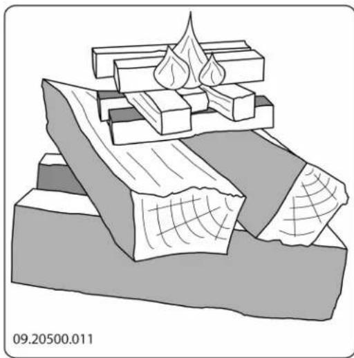
- Close the door of the appliance and open the If the logs are stacked openly, the wood will burn primary air inlet and the secondary air inlet of th quickly as the oxygen can reach each log easily. If appliance; see the following figure. you want to use the stove for a short while, make an open stack
- Let this fire develop into a good blaze until there is glowing bed of charcoal. You can then add fuel Compact stacking and adjust the appliance, see the chapter "Stoking with wood".
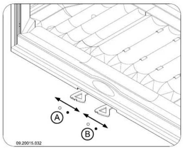
$$ \circ = \text {O p e n} \bullet = \text {C l o s e d} $$
Burning wood
After you have followed the instructions for lighting:
- Slowly open the door of the appliance.
- Spread out the charcoal bed evenly across the bottom of the fire compartment.
- Stack a few logs on the charcoal bed.
Open stacking
If the logs are stacked tightly, the wood will burn more slowly as the oxygen can only reach some logs easily. If you want to burn wood for a longer period, make a compact stack.
- Close the door of the appliance.
- Close the primary air inlet and leave the secondary air inlet open.
Fill the appliance up to one third capacity.
Controlling the air
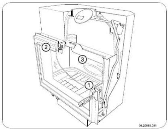
The appliance has various features for the air control (see figure).
It is better to add a small amount of logs regularly than to add many logs at the same time.
Extinguishing the fire
Do not add fuel and just let the fire go out. If a fire is damped down by reducing the supply of air, harmful substances will be produced and released. Therefore, let the fire go out naturally. Keep an eye on the fire until it has gone out. When the fire has died completely, all air inlets can be closed.
Removing ashes
The primary air slide controls the air flow under theAfter the wood has been burnt, a relatively small grille (1). amount of ashes is left over. This bed of ashes is a good insulating layer for the bottom of the fire the glass (air-wash) (2). compartment and improves combustion. Therefore, you can leave a thin layer of ashes on the bottom of The back wall has permanent vents (3) below the the fire compartment.
Advice
Regularly burn wood with intense roaring firesplate. Therefore, remove any excess ash frequently.
If you frequently have low intensity fires, tar 1. Open the door of the appliance. and creosote may be deposited in the chimney. Open the ash removal port (C); see next figure.
. Tar and creosote are highly combustible substances. Thicker layers of these substances might catch fire when the temperature in the chimney increases suddenly and steeply. Therefore it is necessary for the fire to regularly burn very intensely, so that layers of tar and creosote disappear.
Low intensity fires also cause tar deposits on the stove window and door. When the outside temperature is not very low it is better to burn wood intensely for a few hours instead of having a low intensity fire for long period of time.
Control the air supply with the secondary air inlet
The secondary air inlet not only supplies air to the fire but to the glass as well, so that it does scrape the excess ash into the ashpan (A) using not get dirty so quickly.
- Open the primary air inlet for the time being if the using the cold hand (B) supplied, remove and supply by the secondary air inlet is inadequate or if empty the ashpan.
you want to fan the fire.

- Put the ashpan back into the appliance and remove the cold hand.
- Close the door of the appliance.
Fog and mist
Fog and mist hinder the flow of flue gases through the fire-resistant inner plates are consumables and flue. Smoke can blow back and cause a stench. If it is subject to wear. Check the fire-resistant inner plates not strictly necessary, it is better not to use the stove frequently and replace them when necessary.
in foggy and misty weather.
Solving problems
Refer to the appendix "Diagnostic diagram" to solve any problems in using the appliance.
Maintenance
Follow the maintenance instructions in this chapter to keep the appliance in good condition.
Chimney
In many countries, people are legally required to have their chimney checked and maintained.

be the chapter "Installation" for instructions on moving and installing the inner plates.

The insulating vermiculite inner plates may develop hairline cracks, but that does not affect their performance adversely.

Cast-iron inner plates go a long way if you frequently remove the ash that may pile up behind them. If accumulated ash behind a cast-iron plate is not removed, the plate cannot dissipate the heat anymore to its surroundings and that may cause the plate to warp or crack.
Never use the appliance without the fireresistant inner plates.
At the beginning of the heating season: have the Cleaning glass chimney swept by an expert.
During the heating season and after the chimneyas follows: has not been used for a long time: have the chimney checked for soot deposits. 1. Remove dust and loose soot with a dry cloth.
After the heating season: seal off the chimney with Clean the glass with stove window cleaner:
Clean the glass with stove window cleaner:
Cleaning and other regular maintenance activities

Do not clean the appliance when it is still warm.
Clean the exterior of the appliance with a dry lint free cloth.
At the end of the heating season, you can clean interior of the appliance thoroughly:
If necessary, first remove the fire-resistant inner plates. See the chapter "Installation" for instructions on removing and installing the inner plates.
a. Apply stove window cleaner to a kitchen sponge, rub down the entire glass surface and give the cleaning agent time to react.
b. Remove the dirt with a moist cloth or kitchen tissue.
- Clean the glass again with a normal glass cleaning product.
Rub the glass clean with a dry cloth or kitchen tissue.
e Do not use abrasive or aggressive products to clean the glass.
Wear household gloves to protect your hands.
If the glass in the appliance is broken or cracked, it must be replaced before you can use the appliance again.
Make sure that no stove window cleaner runs between the glass and the cast-iron door.
Let the sealant harden fully before you start a fire in the appliance, because otherwise any moisture in the sealant will form bubbles in the sealant and cause a new air leak.
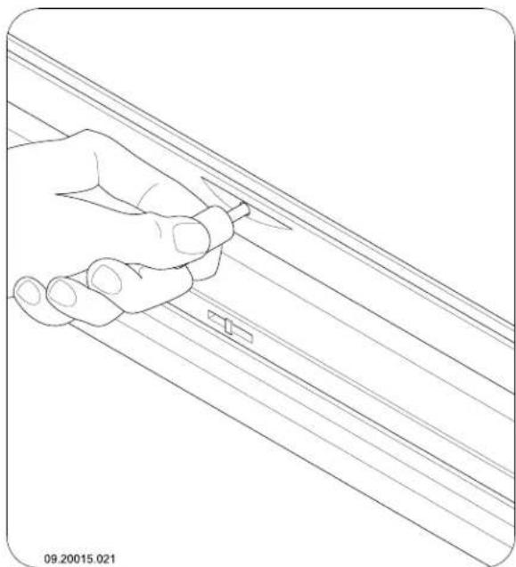
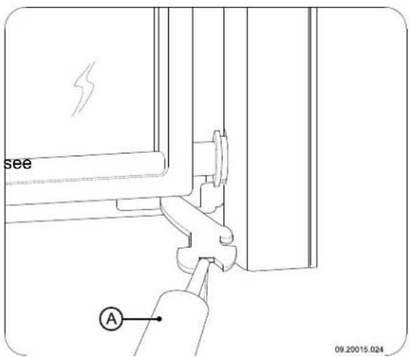
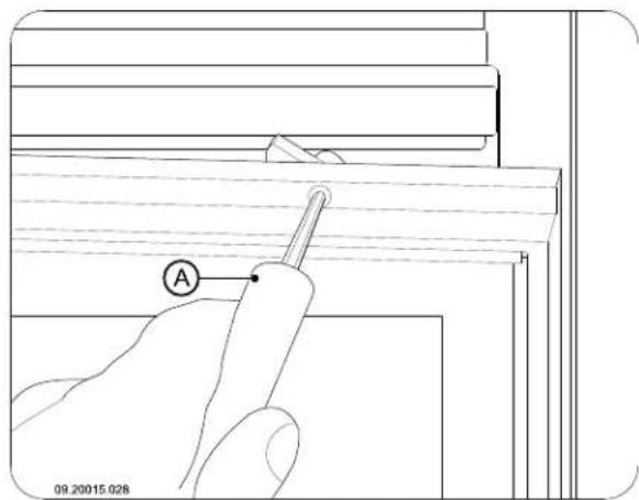
Panoramic lifting door: model 2180CBGD
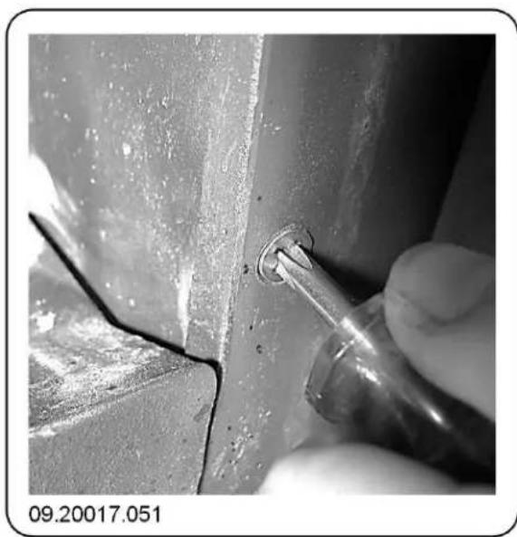
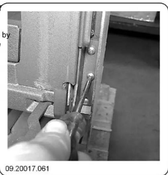
Note: To gain access to the inside glass of the lift door of model 2180CBGD, you can tilt the door forward 60^ . Use a screwdriver (A) to turn the two screws in the top of the door to the left; see next figure.
Lubrication
Model 2180CBGD has a flat, panoramic lifting door. The guiding system can be removed and the position of the door can be adjusted.
Dismantling the guiding system
For dismantling, follow the steps below.
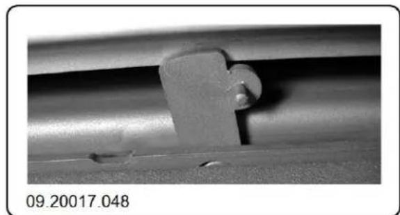
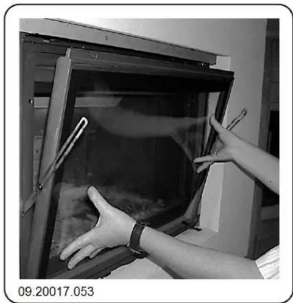
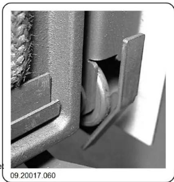
- Lock the door by turning the two locks above the door outward; see next figure.
Although cast-iron is slightly self-lubricating, you will still have to lubricate moving parts frequently.
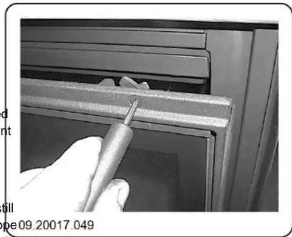
- Turn the two screws in the top of the door to the left; see next figure. The door will now tilt forward.
Lubricate the moving parts (such as guide systems, hinge pins, latches and air slides) with heat resistant grease that is available in the specialist trade.
Touching up the finish
Small areas of damaged paint finish can be touched up with a spraying can of special heat-resistant paint finish available from your supplier.
Checking the seal
Check whether the sealing rope of the door is still in good condition and works well. The sealing rope09.20017.049 is subject to wear and needs to be replaced in time.
Check the appliance for air leaks. Close any chinks with stove sealant.
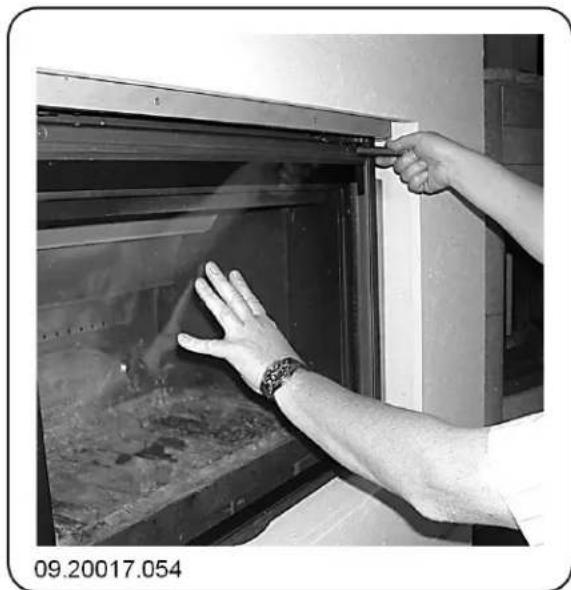
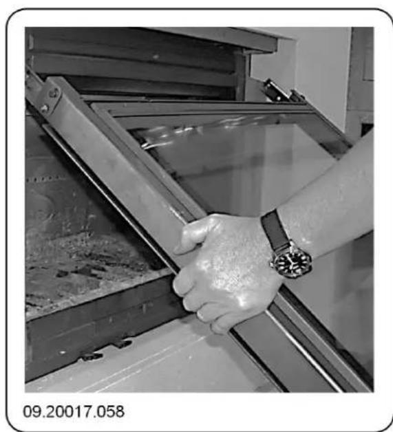
- Remove the front (with door and guiding system) from the top part by removing the screws at top left and right; see next figure.
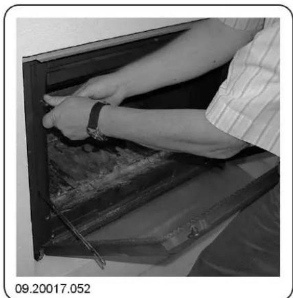
- Unscrew the front from the appliance. Remove the 6 Now carefully close the door while it is tilted two bottom screws first; see next figure. forward; see next figure.
- Then remove the two top screws. Hold the front 7. Lock the door; see next figure. against the appliance with your body; see next figure.
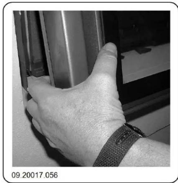
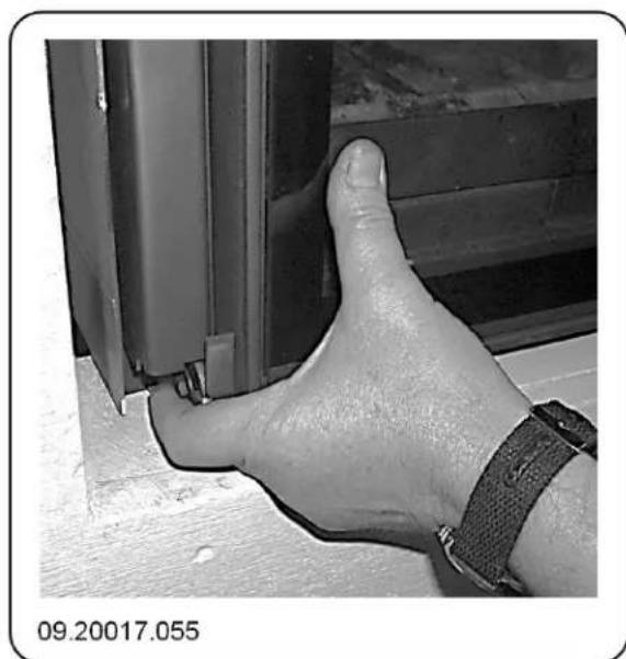
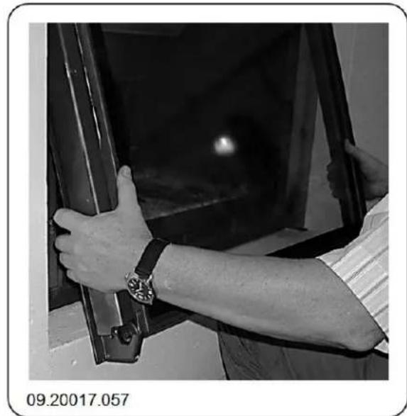
- Grasp the front and the door at the bottom together the assembly from the appliance; see next with the guiding system; see next figure.
-
Now pull the front and the door forward at the bottom; see next figure.
-
The guiding system is now freely accessible; see next figure.
Note: To fit the guiding system, follow the steps set out above in the reverse order.
2. Press the door against the bottom of the front so that the guide wheel just touches the closing bracket; see next figure.

Adjusting the closure of the lift door
The position of the door relative to the front can be adjusted. The guiding system should be freely accessible. Remove the cover profiles or the frame, if fitted.
- Loosen the bolt on the side and adjust the door pressing it against the front. Tighten the nut; see next figure.
necessary, adjust the position of the closing bracket by loosening the three mounting screws and moving the closing bracket. Tighten the screws; see next figure.
Appendix 1: Technical Data
| Series 2180CB | |
| Nominal output 15 kW | |
| Chimney connection (diameter) 200 mm | |
| Weight +/- 190 kg | |
| Weight model 2180CBGD 230 kg | |
| Recommended fuel Wood | |
| Fuel property, max. length 50 cm | |
| Mass flow of flue gases 13.6 g/s | |
| Temperature increase measured in measuring section | 268 K |
| Temperature measured at the appliance outlet | 326 °C |
| Minimum draught | 12 Pa |
| CO emission (13%2) | 0,10 % |
| NOx emission (13%2D) | 97 mg/Nm3 |
| CnHm emission (13%2) | 96 mg/Nm3 |
| Particulate emission | 22 mg/Nm3 |
| Efficiency | 76 % |
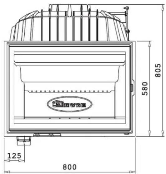
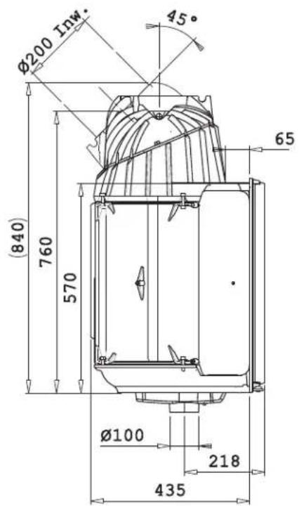
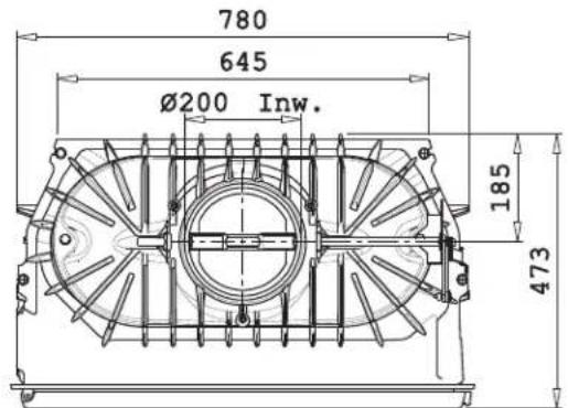
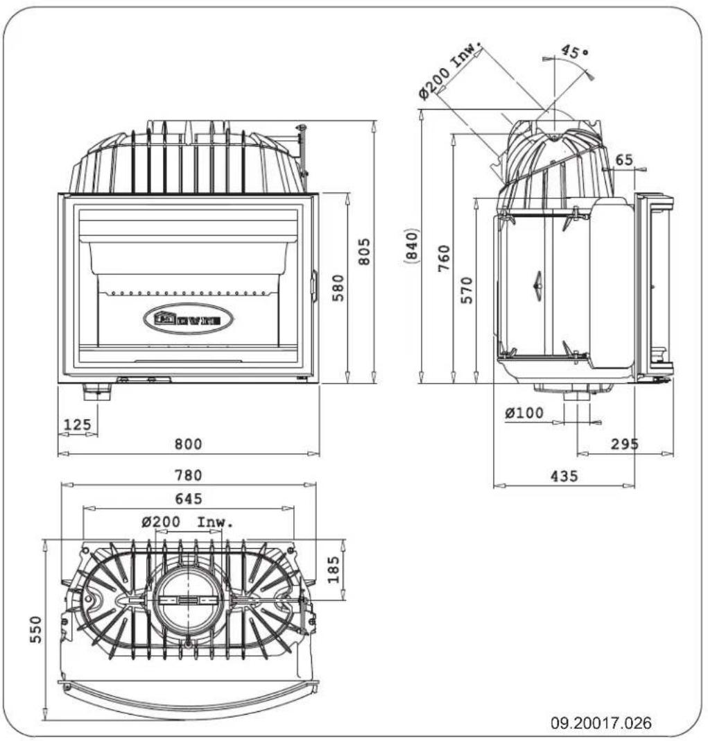
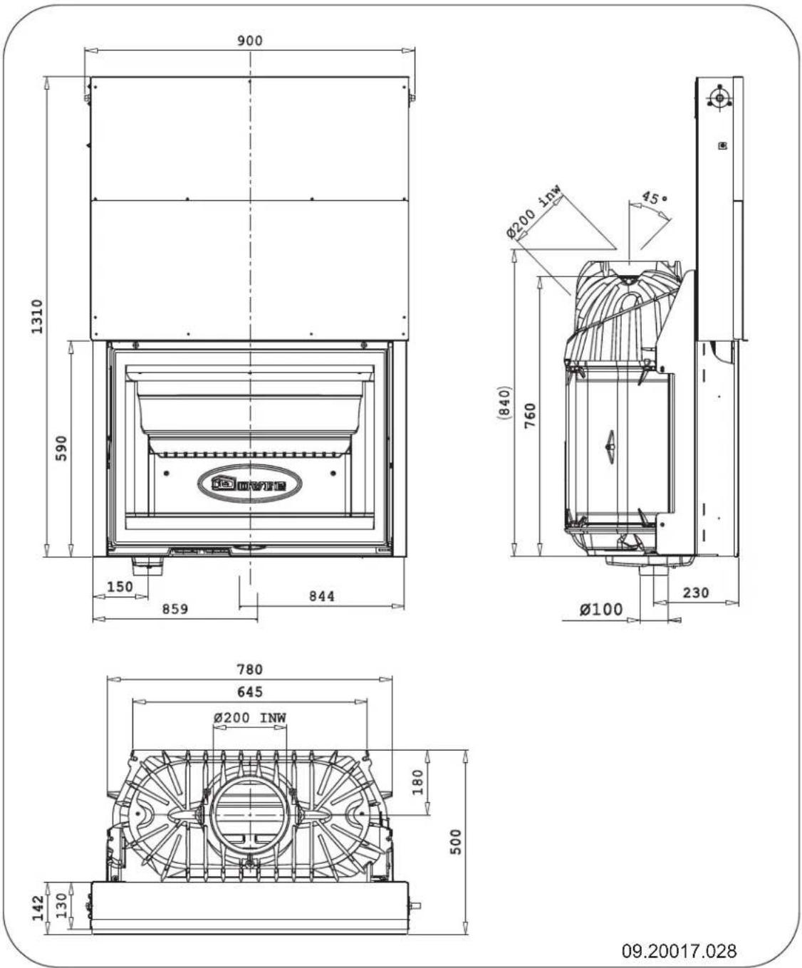
Appendix 2:Measurements
2180CBS and 2180CBC
09.20017.024
2180CBBS
2180CBGD
Appendix 3: Distance from combustible material
Series 2180CB; Minimum ventilation space outside the radiation range
Series 2180CB - Dimensions of fireproof floor plate in centimetres
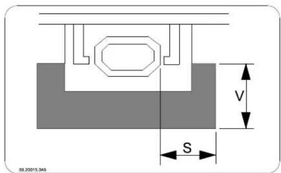
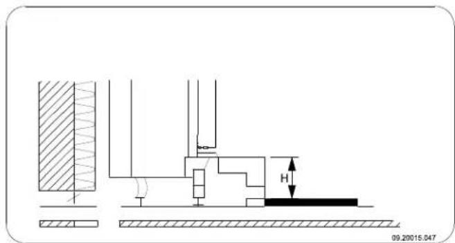
Minimal dimensions of fireproof protective plate
$$ V > H + 3 0 > 6 0 $$
$$ S > H + 2 0 > 4 0 $$
Appendix 4: Diagnostic diagram
| Problem | ||||||
| ● | Wood does not keep burning | |||||
| ● | Gives off insufficient heat | |||||
| ● | Smoke emissions into the room when adding wood | |||||
| ● | Fire in appliance is too intense, is hard to adjust | |||||
| ● | Deposit on the glass | |||||
| Possible cause Possible | solution | |||||
| ● | ● | ● | ● | Insufficient draught | A cold flue usuallyfails to create sufficient draught. Follow the instructions for lighting in the "Use" chapter; open a window. | |
| ● | ● | ● | ● | Wood too damp Use wood with no more | more than 20% moisture. | |
| ● | ● | ● | ● | Pieces of wood too big | Use smallpieces of kindling. Use split logs no larger than 30 cm in circumference. | |
| ● | ● | ● | ● | ● | Wood stacked up incorrectly | Stackup the wood in a way that allows an adequate air flow between the logs (open stacking, see "Burning wood") |
| ● | ● | ● | ● | Chimney does not work properly | Check whether the chimney meets the requirements: at least 4 metres high, right diameter, well insulated, smooth inside, not too many bends, no obstructions in chimney (bird'snest, too much soot deposit), hermetically tight (no chinks). | |
| ● | ● | ● | ● | Chimney stack incorrect Sufficiently high | high above the roof, no obstacles in its vicinity | |
| ● | ● | ● | ● | ● | Air inlets set incorrectly Open the air | inletscompletely. |
| ● | ● | ● | ● | Appliance connected to chimney incorrectly | Connection should be hermetically tight. | |
| ● | ● | ● | ● | Vacuum in area where appliance is installed | Switch off extraction systems. | |
| ● | ● | ● | ● | Insufficient supply of fresh air | Provide an adequate air supply; if necessary use connection to outside air. | |
| ● | ● | ● | ● | Adverse weather conditions? Inversion (reversed air flow in chimney because of a high outside temperature) extreme wind velocities | We recommend you don't use the appliance in the case of inversion. Install an extra hood on the flue to increase the draught if need be. | |
| ● | Draught in the living room | Avoid draught in the living room, do not place the appliance near a door or heating air ducts. | ||||
| ● | Flames touch the glass | Make sure the wood does not lie too close to the glass. Slide the primary air inlet cover closer to the "Closed" position. | ||||
| ● | Appliance isleaking air Check the door seals and the appliance joints. | |||||
Index
A
Adding fuel 16
Adding wood smoke emissions into the room. 27
Adjusting closure of the lifting door 21. damper.8
Adjustung the lifting door. 21
Air control.15.
Air inlet grate
placing.12
requirements.12
Air inlets.15
Air leak 18
Air outlet grate
placing.13
requirements..13
Air supply for fire 16.
Ashes remove
B
Baffle plate 8. Bearing capacity of floor Floors bearing capacity
Burning wood 15
add fuel. 16
adding logs. 15
appliance is hard to adjust. 27
fire is too intense. 27
insufficient heat. 17, 27
C
Carpet. 6
Chimney
connection diameter. 22
connection to. 12
height. 5
sweep 17
Chinks in appliance 18
Clean glass. 17
Cleaning appliance 17
Combustible material distance from 26
Connection measurements 23
Connection collar. 9
Connection to supply of outside air.. 11
Control air supply. 16
Control of air. 15
Convection space construction 12 cover plate. 12 instructions 12
Counterweight 22
unblocking 7
Cover on flue 5
Cover plate convection space 12
Creosote 16
D
Damp wood 14
Damper adjusting 8
Dismantling baffle plate 8
Door sealing rope. 18
Draught 22
Drying of wood 14
E
Efficiency. 22
F
Filling height. 15
Finishing coat, maintenance. 18
Fire extinguishing 16 lighting.14
Fire-resistant inner plates maintenance. 17
Fire going out 16
Fire safety distance from combustible material 26 floor. 6
furniture.6
walls.6
Fireproof inner plates
warning 14
Floors
fire safety 6.
Flue
maintenance 17
requirements. 4
Flue gas
mass flow.22
Flue temperature_22
Fog, do not burn wood.17.
Fuel
adding. 16
adding wood 15
Heat, insufficient.17
Heat,insufficient 27
Hood on the flue. 5
1
Installation
measurements 23
K
Kindled fire 14
Kindling 27
L
Lifting door 7
adjusting 21
counterweight. 7
guiding system 18
Lighting 14
Lubricant. 18
Lubricate 18
M
Maintenance
chimney. 17
clean glass 17
cleaning the appliance. 17
fire-resistant inner plates 17
lubrication 18
sealing 18
Measurements. 23
Mist, do not burn wood 17
N
Nominal output 17, 22
0
Outside air intake
connection to 12
P
Paint finish 14
Particulate emission 22
Prevent a chimney fire. 16
Primary air inlet. 15
R
Removal of ashes 16
Remove ashes 16
s
Screens
clean 17
deposit 27
Sealing rope for door 18
Secondary air inlet. 15
Smoke
on first use. 14
Smoke emissions into the room 4, 27
Softwood 14
Solving problems 17, 27
Stacking logs 15
Storing wood 14
Stove window cleaner.17
Suitable fuel 14
Supply of outside .air.5.1.1
Sweep chimney.17
T
Tar 16
Temperature increase measuring section.22
U
Unsuitable fuel 14
V
Ventilation 5. connect supply of outside. air..11. rule of thumb 5
Ventilation louvre.5
W
Walls fire safety. 6
Warning chimney fire 4, 14, 16
combustible materials 4
fireproof inner plates. 14
glass broken or cracked. 4, 18
hot surface 4
regulations 4
stove window cleaner 18
terms and conditions for insurance. 4
ventilation 4-5
Weather conditions, do not burn wood. 17
Weight 22
Wood 14
damp 14
does not keep burning. 27
drying 14
right sort 14
storing 14
Table des matieres
Introduction 3
Raccordement dimensions Pose
dimensions 24
Calore, insufficiente 17, 28