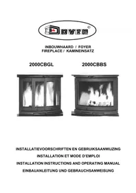
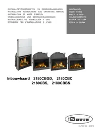
ZEN 102 - Fireplace DOVRE - Free user manual and instructions
Find the device manual for free ZEN 102 DOVRE in PDF.
| Product type | Chimney / Built-in wood stove |
| Brand | Dovre |
| Model | ZEN 102 |
| Recommended fuel | Dry natural wood (moisture ≤ 20%, max length 30 cm) |
| Nominal power | 4.75 kW |
| Efficiency | 80.1 % |
| Chimney connection (diameter) | 150 mm |
| Weight | 100 - 115 kg |
| Main material | Cast iron and steel |
| Minimum draft | 12 Pa |
| Flue gas outlet temperature | 247 °C |
| CO emissions (at 13% O2) | 0.09 % |
| NOx emissions | 111 mg/Nm³ |
| Dust emissions | 293 mg/Nm³ |
| Safety distance (rear) | 50 mm (with insulation) |
| Safety distance (side) | 60 mm (with insulation) |
| Routine maintenance | Glass cleaning, ash removal, greasing moving parts |
| Wear parts | Vermiculite refractory plates, glass, seal cord, gaskets |
| Repairability | Spare parts available (plates, glass, gaskets, etc.) - contact distributor |
| Warranty | Consult authorized distributor |
Frequently Asked Questions - ZEN 102 DOVRE
User questions about ZEN 102 DOVRE
0 question about this device. Answer the ones you know or ask your own.
Ask a new question about this device
Download the instructions for your Fireplace in PDF format for free! Find your manual ZEN 102 - DOVRE and take your electronic device back in hand. On this page are published all the documents necessary for the use of your device. ZEN 102 by DOVRE.
USER MANUAL ZEN 102 DOVRE
Performance declaration 4
Safety 6
Installation requirements 6
General 6
Flue 6
Room ventilation 7
Floor and walls 8
Product description 8
Installation 9
General preparation 9
Prepareconnection to outside air 10
Building into a new hearth 10
Use 12
First use 12
Fuel 13
Lighting 13
Burning wood 13
Controlling combustion air. 14
Extinguishing the fire 15
Removing ash. 15
Fog and mist 15
Resolving problems 15
Maintenance 16
Flue 16
Cleaning and other regularly maintenance. 16
Appendix 1: Technical data. 18
Appendix 2: Dimensions 19
Appendix 3: Distance from combustible
material 21
Appendix 4: Diagnosis diagram. 23
Index 24
Introduction
Dear user,
By purchasing this heating appliance from DOVRE you have selected a quality product. This product is part of a new generation of energy-efficient and environmentally-friendly heating appliances. These appliances make optimum use of convection heat as well as thermal radiation (radiant heat).
- Your DOVRE appliance has been manufactured with state-of-the-art production equipment. In the unlikely event of a malfunction, you can always rely on DOVRE for support and service.
The appliance should not be modified; please always use original parts.
The appliance is intended for use in a living room. It must be hermetically connected to a properly working flue.
We advise you have the appliance installed by an authorized and competent installer.
DOVRE cannot be held liable for any problems or damage resulting from incorrect installation.
Observe the following safety regulations when installing and using the appliance.
In this manual, you can read how the DOVRE heating appliance can be installed, used and maintained safely. Should you require additional information or technical data, or should you experience an installation problem, please first contact your supplier.
© 2014 DOVRE NV
Performance declaration
In accordance with construction products regulation 305/2011
No.116-CPR-2014
- Unique identification code of the following product type:
ZEN
- Type, batch or serial number or other form of identification for the construction product, as scribed in article 11, subsection 4:
Unique serial number.
- Intended use for the construction product, in accordance with the applicable harmonised techr specification, as specified by the producer:
Stove for solid fuel without production of warm water in accordance with EN 13229
- Name, registered trade name or registered trademark and contact address of the producer, as scribed in article 11, subsection 5:
- If applicable, name and contact address for the authorised whose mandate covers the tasks cified in article 12, subsection 2:
-
- The system or systems for the assessment and verification of the performance durability of construction product, specified in appendix V:
System 3
- If the performance declaration concerns a construction product for which a harmonised norm issued:
The appointed KVBG agency, registered under number 2013, has performed a type test under system 3 and has issued the test report no. H2014/0030.
- If the performance declaration concerns a construction product for which a European technical assessment is issued:
9. Declared performance:
| The harmonised norm EN 13229:2001/A2 ;2004/AC :2007 | |
| Essential characteristics Performance Wood | |
| Fire safety | |
| Fire resistance A1 | |
| Distance from combustible material | Minimum distance in mmRear: 50 with insulationSide: 60 with insulation |
| Risk of glowing particles falling out Conform | |
| Emission of combustion products CO: 0.09% (13%O2) | |
| Surface temperature | Conform |
| Electrical safety | - |
| Ease of cleaning | Conform |
| Maximum operating pressure | - |
| Flue gas temperature at nominal output | 175 °C |
| Mechanical resistance (weight carry of chimney) | Not determined |
| Nominal output | 4.75 kW |
| Efficiency | 80.1 % |
- The performance of the product described in points 1 and 2 conform with the performance in point 9.
This performance declaration is supplied under the exclusive responsibility of the producer specifi in point 4:
10/02/2014 Weelde
Tom Gehem
CEO
Due to continuous product improvement, the supplied appliance specifications may vary from the description in this brochure without prior notice having been given.
DOVRE N.V.
Please note: All safety regulations must be complied with strictly.
Please read carefully the instructions supplied with the appliance for installation, use and maintenance before using the appliance.
The appliance must be installed in accordance with the legislation and requirements applicable in your country.
All local regulations and the regulations relating General to national and European standards must be observed when installing the appliance. The applia
The appliance should preferably be installed by an authorised installer. Installers will be aware of the applicable regulations and requirements. For connection measurements: see "Technical data" appendix.
The appliance is designed for heating purposes. All surfaces, including the glass and connecting tube, can become very hot (over 100^ ! When operating, use a so-called "cold hand" or an oven glove. Flue
Make sure there is sufficient protection if The flue is needed for: young children, disabled persons or old people are in the vicinity of the appliance. Removal of combustion
Safety distances from flammable materials As the warm air in the flue or chimney is lighter must be strictly adhered to. than the outside air, it rises.
Do not place any curtains, clothes, laundry or Air intake, needed for the combustion of fuel in the other combustible materials on or near the appliappliance.
ance. A nearly functioning flux or chimney can cause smoke
When in use, do not use flammable or explosive substances in the vicinity of the appliance. Damage caused by smoke emissions into the room is not covered by the warranty.
Avoid chimney fires by having the chimney swept regularly. Never burn wood with the door Do not connect multiple appliances (such as a boiler for central heating) to the same flue,
In the event of a chimney fire: close all the
appliance's air inlets and alert the fire service. unless local or national regulations allow this. In the event of two connections ensure that the difference in height between the connections is
If the glass in the appliance is broken or no less than 200~mm
The appliance must be connected tightly to a well-functioning flue.
For connection measurements: see "Technical data" appendix.
- Ask the fire service and/or your insurance company about any specific requirements and regulations.
The flue is needed for:
- Removal of combustion gases via natural draught.
As the warm air in the flue or chimney is lighter than the outside air, it rises.
Air intake, needed for the combustion of fuel in the pool appliance.
A poorly-functioning flue or chimney can cause smoke to escape into the room when the door is opened. Damage caused by smoke emissions into the room is not covered by the warranty.
Ensure that there is adequate ventilation in the room in which the appliance is installed. If ventilation is insufficient, combustion will be incomplete whereby in toxic gases can spread through the room. See the chapter "Installation requirements" for more information on ventilation.
Installation requirements
General
Flue
Ask your installer for advice regarding the flue. Refer to the European norm EN13384 for a correct calculations for the flue.
The flue must satisfy the following requirements:
The flue or chimney must be made of fire-resistant material, preferably ceramics or stainless steel.
The flue or chimney must be airtight and well-cleaned and guarantee sufficient draught.
i
A draught/vacuum of 15 - 20 Pa during normal operation is ideal.
Starting from the flue spigot, the flue must run a vertically as possible. Changes in direction and horizontal pieces disrupt the outward flow of combustion gases and may cause soot deposits.
To prevent combustion gases from cooling down too much, which reduces the draught, ensure that the interior diameter is not too big.
The flue or chimney should ideally have the same diameter as the connection collar.
Room ventilation
For good combustion, the appliance needs air (oxy-gen). This air is supplied via adjustable air inlets from the area in which the appliance is installed.
If ventilation is insufficient, combustion will be incomplete, which may lead toxic gases to spread through the room.
i
For nominal diameter: see "Technical data" appendix. If the smoke channel is well insulated, the diameter may be slightly bigger (up 2x the section of the connection collar).
The section (area) of the smoke channel must constant. Wider segments and (in particular) narrower segments disrupt the outward flow of combustion gases.
In fitting a cover plate/exhaust cap to the flue: You can provide extra ventilation by having a ventmake sure that the cover does not restrict the fluation louvre fitted on the outside wall. outlet and that the cap does not impede the outMake sure that other air consuming appliances (such ward flow of combustion gases. as tumble-driers, other heating appliances or a bath
The flue must end in a zone that is not affected by room fan) have their own supply of outside air, or are surrounding buildings, trees or other obstacles switched off when you use the appliance.
The flue outside the house must be insulated.
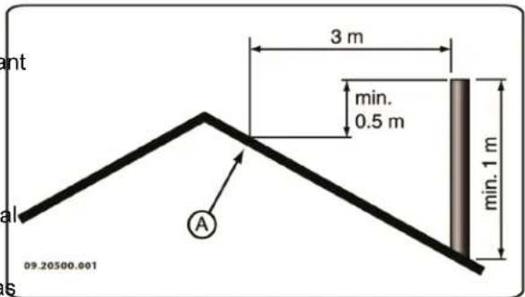
The flue should be at least 4 metres high.
As a rule of thumb: 60 cm above the ridge of the roof.
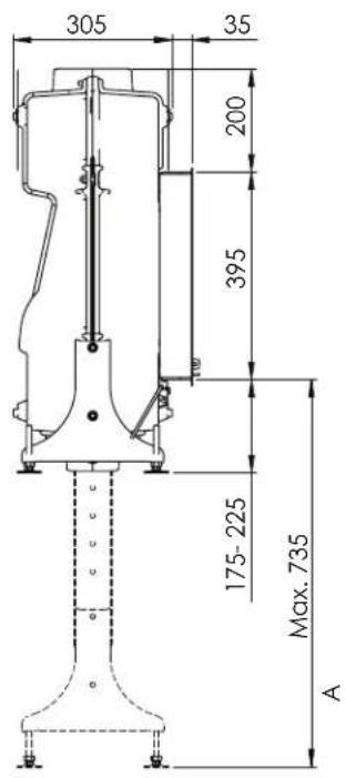
If the ridge of the roof is more than 3 metres from the flue: use the measurements given in the following figure. A = the highest point of the roof within a distance of 3 metres.
Floor and walls
The floor on which the appliance is placed must have sufficient bearing capacity. The weight of the appliance is given in the appendix "Technical Data appendix".

Protect flammable flooring from heat radiation by means of a fireproof protective plate. See the appendix "Distance from combustible material".

Remove combustible material such as linoleum, carpets/rugs and similar materials below the fireproof protective plate.

Keep sufficient distance between the appliance and combustible materials such as wooden walls and furniture.

The connecting tube also radiates heat. Ensure that there is sufficient distance or a shield between the connecting tube and combustible material.
The rule of thumb for a single-walled tube is a distance of 3x the diameter. If a lining shell is fitted around the tube, a distance of 1x the diameter is permissible.

Carpets and rugs must be at least 80 cm away from the fire.

Use a fireproof floor plate to protect a flammable floor from any ash which may fall in front of the stove. The floor plate must comply with national standards.

For the dimensions of the fireproof protective plate: see the appendix "Distance from combustible material".

For further requirements with respect to fire safety, see the appendix "Distance from combustible material".
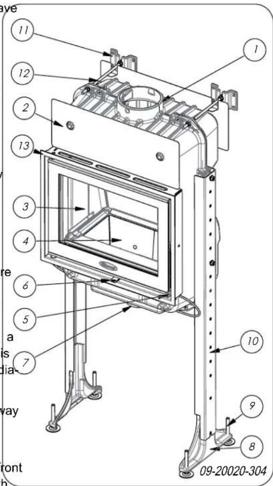
- Connection collar
- heat shield
- Door
- Bottom of the fire compartment
- Latch
- Air slide
- Connection to outside air
- Support
- Adjustable feet
- Extension (optional)
-
Stays (optional)
-
Threaded rod M8 (optional)
- Finishing cover
Installation
General preparation
- Please check the appliance immediately after delivery for damage during transport or any other damage or defects. The appliance is attached to the pallet with screws at the bottom.
If you detect transport damage or any other damage or defects, do not use the appliance and notify the supplier. - Remove the detachable parts from the appliance before you begin its installation.
It is easier to move the appliance and to avoid damage if the removable parts have been removed.
Note the location of the removable parts, so 1 2 that you can re-position the parts in the correct place later on. 3
Open door
Open the door by pulling the handle forward and unlocking the door; see next figure.
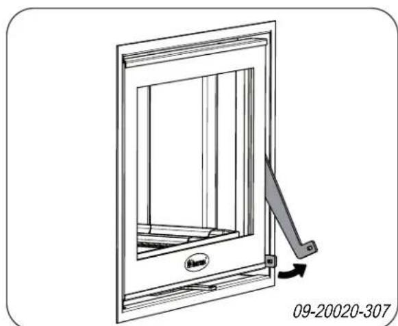

As the latch button becomes warm during use, The stove base is protected by fire-resistant inner of the appliance, a glove has been supplied plates. Remove these inner plates first and then which you can use to protect your hand. remove the stove base from the appliance.
Remove fire-resistant inner plates

Vermiculite inner plates are light and tend to be ochrous in colour on delivery. They insulate the combustion chamber to boost combustion.
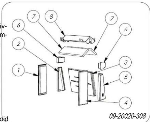
Pos. Description
1 inner plate front left
2. inner plate left rear
3 inner plate at rear
4 inner plate front right
5 inner plate right rear
6 inner plate top
7 baffle plate
8 baffle plate holder
To remove the inner plates, follow the instructions below; see previous figure.
- First remove the inner plates on the side (1),(2),(4) and (5) by lifting these up and out of the appliance via the door opening.
- Remove both inner plates (6).
- Remove the inner plate (3).
- Remove both baffle plates (7) from the baffle plate holder (8).
- Remove the baffle plate holder (8).
Remove stove base
i
Chamotte inner plates are ochrous on deliverylength (12 m) must be reduced by 1 m for each access. They insulate the combustion chamber to ory used.
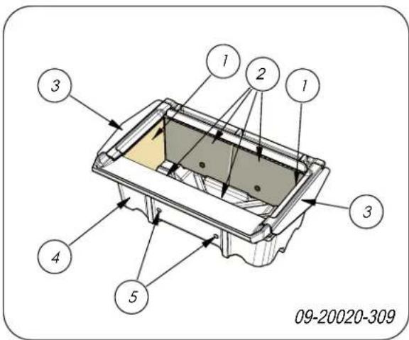
Pos. Description
1 side inner plate
2 inner plate front and rear
3 air guide
4 stove base
5 vents
To remove the inner plates and the stove base, the instructions below; see previous figure.
- Remove the air guides (3) on the left and right sides.
- First remove both inner plates (1) on the sides by tipping them forwards and removing them from the appliance via the door opening. 3.
- Remove the inner plates (2) at the front and rear:
- Remove the stove base (4).
A
When reassembling the stove base, make sure the two vents (5) are facing forward.
Prepare
connection to outside air
If the appliance is installed in a room with insufficient ventilation, you can install the outside air connecting kit to the appliance.
The air supply tube is 100mm in diameter. If the is smooth, it may be no longer than 12 metres. If accessories such as bends are used, the maximum
Outside air intake duct through the wall or the floor and the connection collar
- Make a hole in the wall or the floor (refer to Appendix 2, "Dimensions" for a suitable position of the hole).
- Close the air connection tube hermetically on the wall.
Building into a new hearth
The fireplace insert is installed in two stages:
Placing and connecting the fireplace
Building up the hearth around the fireplace.
Placing and connecting the fireplace insert
- Place the appliance at the right height, flat and level.

You may wish to use the optional legs and stays.
- Make sure there is sufficient space between the existing walls (insulated as per instructions) and by the rear of the appliance.
- Connect the appliance to the flue hermetically.
Check the draught in the flue and the seal of the connection on the flue gas duct by making a small, intense trial fire with newspaper and dry, small kindling.

Wait until new masonry has dried sufficiently.
- For outside air supply connection: connect the outside air supply to the connection kit you fitted to the appliance.
Building the fireplace
Inside the hearth you provide space for convection. In this space the air must be able to move freely. It must be possible for air to be drawn in for combustion purposes, and the air heated by the built-in fireplace (the
convection air) must be able to flow freely within the space to be heated; see following figure.
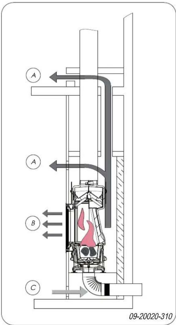
A Convection air current
B Radiated heat
C Air supply from the room to be heated
When building the hearth, follow these instructions for the convection space:
The top of the convection space must be closed tight using a cover plate of non-flammable and heat-resistant material.
The cover plate must be level and placed at least 30~cm below the flue opening in the ceiling.
Air inlet grates must be fitted at the bottom of the
hearth to allow for ambient air intake. The minimum air inlet opening is 250^2 .cfh the space is not sufficiently ventilated, you must provide for outside air to be allowed in by means of the outside air connection kit or an optional adjustable damper.
Air outlet grates must be installed at the top of the hearth just below the cover plate. The minimum air outlet opening is 500^2cm
The inlet and outlet grates are available as options.
Do not use combustible material in the convection space, and avoid the effect of thermal bridging when using materials that conduct heat.
Follow the instruction below when building the hearth:
- Build the base of the hearth and fit the air inlet grates into the masonry.
You can place the air inlet grates on all sides of the base.
Make sure the door of the appliance can swing freely over the hearth floor.
- Build the hearth up to the smoke dome.
Ensure that a clearance of 2mm is maintained between the built-in fireplace and the masonry to accommodate the thermal expansion of the fireplace.
- The inside of the convection space may, if desired, be cladded with reflective, insulating material.
Additional cladding of the convection space prevents unnecessary thermal radiation towards outer walls and/or adjacent rooms. It also prevents damage to the hearth wall insulation. - Build the rest of the hearth up to the flue opening in airhole in the ceiling.
The masonry should not rest on the fireplace. Use a support such as a steel beam. Leave a clearance of at least 3mm between the support and the appliance.
The Close the convection space with the cover plate. - Put the air outlet grates under the cover plate.

- Make an opening above the cover plate in order kInsulation
prevent any pressure build-up.
M Combustible floor
The figure below provides an example of the placing opening to prevent pressure build-up a built-in fireplace in a hearth constructed in accord-O Connection pipe ance with the above instructions.
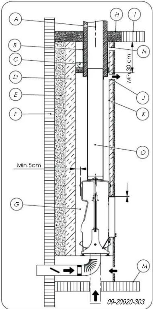
A Flue
B Seal
C Cover plate
D Insulation 10 cm
E
Fireproof wall, min 10cm (e.g. cellular concrete)
F Combustible wall
G Convection space
H Fireproof ceiling
1 Combustible ceiling
J Convection air outlet
Place finishing cover
- Place the four supplied magnets (2) on the side of the frame; see following figure.
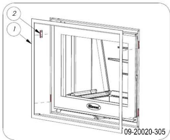
- Slide the supplied cover (1) into the frame.
Finishing
- Re-position all removed parts in the correct places in the appliance.
- Ensure that the newly built hearth is sufficiently dry before you start to use the appliance.

Never use the appliance without the fire-resistant inner plates.
The appliance is now ready for use.
Use
First use
When you use the appliance for the first time, make an intense fire and keep it going for a good few hours. This will cure the heat-resistant paint finish. This may result in some smoke and odours. You could open windows and doors for a while in the area in which the appliance is located.
Fuel
This appliance is only suitable for burning natural wood; sawn and chopped wood that is sufficiently dry. Do not use other fuels, as they can cause serious damage to the appliance.
The following fuels may not be used as they pollute the environment, and because they heavily pollute the appliance and flue, which may lead to a chimney fire:
Treated wood, such as scrap wood, painted wood, impregnated wood, preserved wood, plywood and chipboard.
Plastics, scrap paper and domestic waste.
Wood
Do not use damp wood. Damp logs do not produce Burning wood
Hardwood, such as oak, beech, birch and fruit tree wood is the ideal fuel for your stove. This type of wood burns slowly with calm flames. Softwood contains more resins, burns faster and sparks more.
Use seasoned wood that contains no more than 20% moisture. The wood should have been seasoned for at least 2 years.
Saw the wood to size and split it while it is still 5. fresh. Fresh wood is easier to split, and split wood dries more easily. Store the wood under a roof where the wind has free access.
heat as all the energy is used in the evaporation of moisture. This will result in a lot of smoke and soter you have followed the instructions for lighting: deposits on the appliance door and in the flue. The water vapour will condense in the appliance and 1. Slowly open the door of the appliance. can leak away through chinks in the stove, causing Spread the charcoal evenly across the bottom of black stains on the floor. It may also condense in the stove base. the chimney and form creosote. Creosote is a highly flammable compound and may cause a chm-Stack a few logs on the charcoal. ney fire.
Lighting
You can check whether the flue has sufficient draught by lighting a ball of paper above the baffle plate. A cold flue often has insufficient draught and consequently, some smoke may escape into the room instead of up the chimney. You can avoid this problem by lighting the fire as described below.
Open stacking
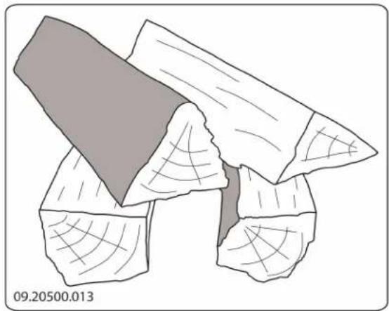
If the logs are stacked openly, the wood will burn quickly as the oxygen can reach each log easily. If you want to use the stove for a short while, make open stack.
Compact stacking
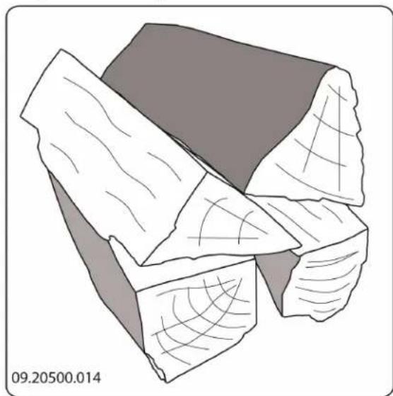
If the logs are stacked tightly, the wood will burn slowly as the oxygen can only reach some logs oily. If you want to burn wood for a longer period, a compact stack.
-
Close the door of the appliance.
-
Close the primary air inlet and leave the secondary air inlet open.

Do not fill the appliance by more than a third.
Controlling combustion air
The appliance has various features for air control; see next figure.
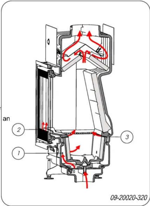
The primary air regulates the air under the stove base (1).
The secondary air regulates the air for the glass (air wash) (2).
The secondary air has vents (3) above the grate that allow for afterburning.
The appliance has one air control system that regulates both the primary air and the secondary air. If the air control is fully to the right, the primary and the secondary air inlet are open. As the air slide is pushed more to the left, this closes off the primary air inlet and the secondary air inlet. If the air slide is completely closed, a small air vent remains open to allow for the afterburning; see following figure.
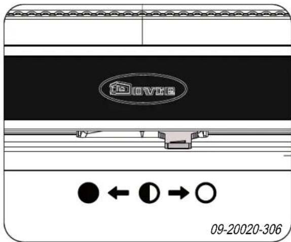
Primary air open (when lighting the stove)
Secondary air open (afterburning)
Glass rinse open
Secondary air open (afterburning) Glass rinse open
Minimum secondary air inlet open (afterburning)
Advice

Never burn wood with an open door.

Stoke the appliance regularly and thoroughly.
If you frequently burn at a low setting, tar and creosote may be deposited in the flue. Tar and creosote are highly combustible substances. Thicker layers of these substances may catch fire if the temperature in the flue increases suddenly. By burning the fire at a high intensity on a regular basis, any layers of tar and creosote will disappear.
Burning at a low intensity can also cause be deposited on the appliance window and door. When the outside temperature is mild, it is ter to burn wood intensely for a few hours instead of having a low intensity fire for a period of time.
Control the air supply using the air vent.

The air inlet not only supplies air to the fire but to the glass as well, so that it does not quickly become dirty.
- Open the primary air inlet for the time being if the air supply by the secondary air inlet is inadequate or if you want to fan the fire.
- Topping up with a few logs regularly is better than adding many logs in one go.
Extinguishing the fire
Do not add fuel and just let the fire go out. If a fire damped down by reducing the air supply, harmful substances will be released. For this reason, the fire should be allowed to go out naturally. Keep an eye on the fire until it has gone out. All air inlets can be closed once the fire has died completely.
Removing ash
After wood has been burnt, a relatively small amount of ash remains. This ash bed is a good insulating layer for the stove base plate and improves combustion. It is a good idea to leave a thin layer of ash on the stove base plate.
The flow of air through the stove base plate must not be obstructed. Remove the excess ash regularly.
- Open the door of the appliance.
- Scoop the excess ash from the appliance or use a special ash vacuum cleaner to remove the excess ash.
Always use an ash vacuum cleaner; using an ordinary vacuum cleaner that has not been specially modified can cause serious damage to an ordinary vacuum cleaner.
d- Close the door of the appliance.
Fog and mist
Fog and mist hinder the flow of flue gases through the flue. Smoke can blow back and cause a stench. If it is not strictly necessary, it is better not to use the stove in foggy and misty weather.
ns Resolving problems
Refer to the appendix "Diagnostic diagram" to resolve any problems in using the appliance.
Maintenance
Follow the maintenance instructions in this chapter to keep the appliance in good condition.
Flue
In many countries, you are required by law to have your chimney checked and maintained.
At the start of the heating season: have the chimney swept by a recognised chimney sweep.
During the heating season and after the chimney has not been used for a long time: have the chimney checked for soot.
At the end of the heating season: close off the ney and plug with newspaper.
Cleaning and other regularly maintenance
Do not clean the appliance when it is still warm.
Clean the exterior of the appliance with a dry lint-free cloth.
You can clean the appliance interior thoroughly at end of the heating season:
If necessary, first remove the fire-resistant inner plates. See the chapter "Installation" for instructions on removing and installing the inner plates.
If necessary, clean the air supply ducts.
- Remove the baffle plate at the top of the applia and clean it.
Checking fire-resistant inner plates
The fire-resistant inner plates are consumables that are subject to wear and tear. Vermiculite inner plate are fragile. Do not knock the inner plates with logs
Check the fire-resistant inner plates frequently and replace them when necessary.
See the chapter "Installation" for instructions on removing and installing the inner plates.
The insulating vermiculite or chamotte inner plates may develop hairline cracks, but this does not affect their performance adversely.
i Cast-iron inner plates last a long time if you remove frequently the ash that can accumulate behind them. If accumulated ash behind the cast-iron plate is not removed, the plate will no longer be able to dissipate the heat to the surroundings and this may cause the plate to warp or crack.
Never use the appliance without the fire-resistant inner plates.
mCleaning the glass
clings less easily to well-cleaned glass. Proceed as follows:
- Remove dust and loose soot with a dry cloth.
- Clean the glass with stove glass cleaner:
a. Apply stove glass cleaner to a kitchen sponge, rub down the entire glass surface and give the cleaning agent time to react.
b. Remove the dirt with a moist cloth or kitchen tissue.
- Clean the glass again with a normal glass cleaning the product.
- Rub the glass clean with a dry cloth or kitchen tissue.
Do not use abrasive or aggressive products to clean the glass.
Wear household gloves to protect your hands.
cse If the glass in the appliance is broken or cracked, it must be replaced before you can use appliance again.
Ensure that no stove glass cleaner runs between the glass and the cast-iron door.
Lubrication
Although cast-iron is slightly self-lubricating, you will still need to lubricate moving parts frequently.
- Lubricate the moving parts (such as guide systems, hinge pins, latches and air slides) with heat resistant grease that is available in the specialist trade.
Touching-up the paint finish
Small areas of damaged paint finish can be touched-up with a spray can of special heat-resistant paint, available from your supplier.
Checking the seal
- Check whether the door sealing rope is still in good condition and works well. The sealing rope is subject to wear and will need to be replaced over time.
Check the appliance for air leaks. Close any chinks with stove sealant.

Allow the sealant to harden fully before lighting the appliance, as any moisture in the sealant will form bubbles, resulting in a new air leak.
Appendix 1: Technical data
| Model ZEN | |
| Nominal output 4.75 kW | |
| Flue connection (diameter) 150 mm | |
| Weight 100 -115 kg | |
| Recommended fuel Wood | |
| Fuel property, max. length 30 cm | |
| Mass flow of flue gasses 5.1 g/s | |
| Flue gas temperature measured in the measurement section 198 °C | |
| Temperature measured at appliance exit 247 °C | |
| Minimum draught | 12 Pa |
| CO emission (13%2) | 0.09 % |
| NOx emission (13%2) | 111 mg/Nm3 |
| CnHm emission (13%2) | 238 mg/Nm3 |
| Particulate emission | 293 mg/Nm3 |
| Particulate emission in accordance with NS3058-NS3059 | 4.76 g/kg |
| Efficiency | 80.1 % |
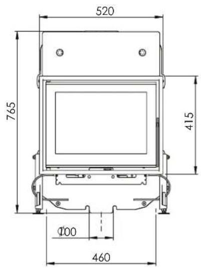
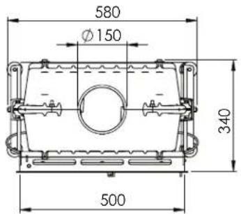
Appendix 2: Dimensions
ZEN 100
09-20020-311
A Optional extension
ZEN 102
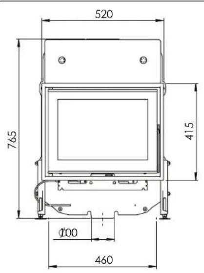
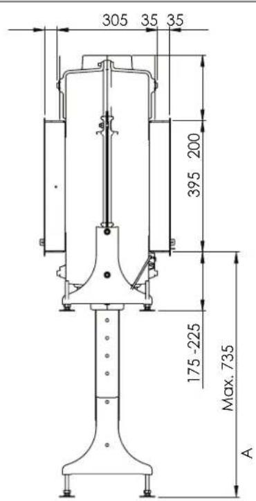
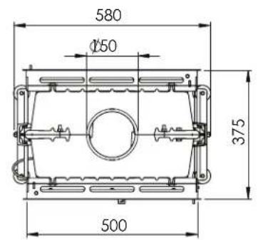
09-20020-312
A Optional extension
Appendix 3: Distance from combustible material
ZEN 100 - Minimum distances in millimetres
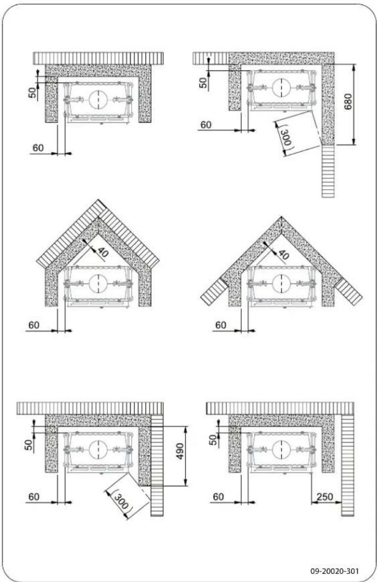
| Combustible material | |
| Incombustible material, thickness 100 mm |
ZEN 102 - Minimum distances in millimetres
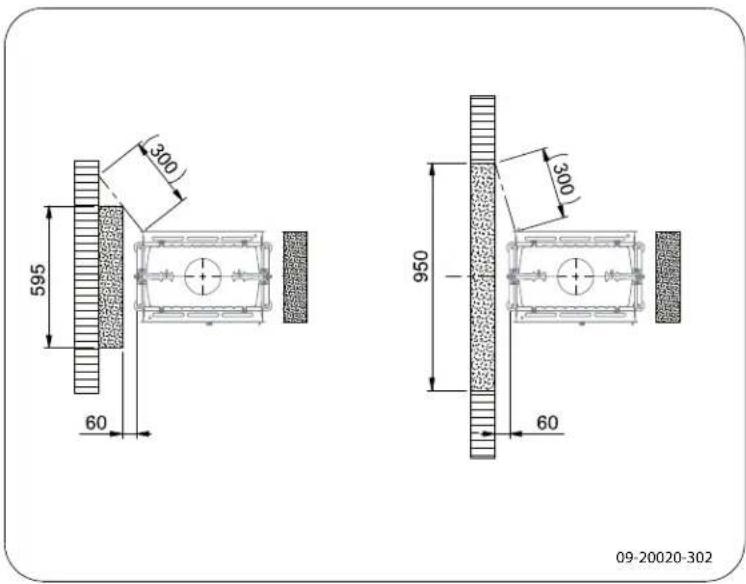
| Combustible material | |
| Incombustible material, thickness 100 mm |
Dimensions of fireproof floor plate in centimetres
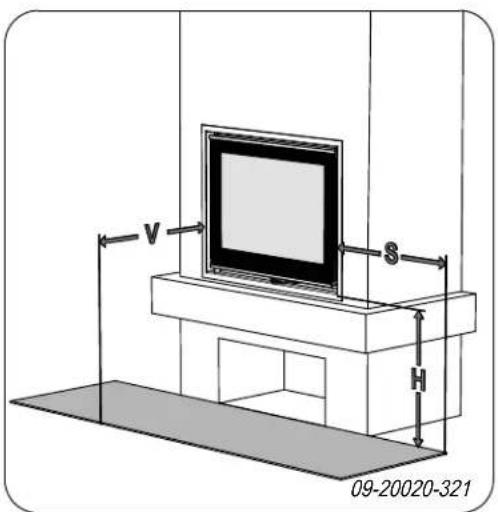
Minimum dimensions of fireproof floor plate
$$ \begin{array}{l} V > H + 3 0 > 6 0 \ S > H + 2 0 > 4 0 \ \end{array} $$
Appendix 4: Diagnosis diagram
| Problem | |||||
| ● | Wood will not stay lit | ||||
| ● | Gives off insufficient heat | ||||
| ● | Smoke emissions into the room when adding wood | ||||
| ● | Fire in appliance is too intense, is hard to adjust | ||||
| Deposit on the glass | |||||
| possible cause possible | solution | ||||
| ● | ● | ● | Insufficient draught | A cold flue usually failsto create sufficient draught. Follow the instruc-tionsfor starting a fire in the 'Use' section; open a window. | |
| ● | ● | ● | Wood too damp Use wood with no more than 20% moisture. | ||
| ● | ● | ● | Logs too large | Use small piecesof kindling. Use split logs no larger than 30 cm in cir-cumference. | |
| ● | ● | ● | ● | Wood stacked incorrectly | Stackthe logs in a way that allows adequate air flow between the logs (open stacking, see "Burning wood") |
| ● | ● | ● | Flue does not workproperly | Check whether the chimney meets the requirements: at least 4 metres high, correct diameter, well-insulated, smooth inside, not too many bends, no obstructions in chimney (bird'snest, too much soot deposit), hermetically tight (no chinks). | |
| ● | ● | ● | Chimney stack incorrect Sufficiently high | high above the roof, no obstacles in the vicinity | |
| ● | ● | ● | ● | Air inlets set incorrectly Open the air | inlets completely. |
| ● | ● | ● | Appliance connected to the flue incor-rectly | Connection should be hermetically tight. | |
| ● | ● | ● | Vacuum in area in which the appliance is installed | Switch off extraction systems. | |
| ● | ● | ● | Insufficient supplyof fresh air | Provide an adequate air supply; if necessaryuse outside air con- nection. | |
| ● | ● | ● | Bad weather? Inversion (reversed air flow in chim- because of a high outside temperature) of required, installan extra hood on the flue to increase the draught. | ||
| ● | Draught in the living room | Avoid draught in the living room, do not place the appliance near a door or heating air ducts. | |||
| Flames touch the glass | Make sure the wood is not positioned too close to the glass. Slide the primary air inlet cover closer to the "Closed" position. | ||||
| ● | Appliance is leaking air Check the door | or seals and appliance joints. | |||
Index
A
Adding wood
smoking stove.23
Adverse weather conditions, do not burn wood 15
Aerating the fire.15.
Air combustion control.14
Air control.14
air inlet grate
requirements.11
Air inlet grate
placement .11
Air leak.17.
Air outlet grate
placement 11
requirements.11
ash 15
Ashes
remove 15
B
Bearing capacity of floor 8
Burning 13
adding fuel 13
appliance is hard to adjust 23
fire is too intense 23
insufficient heat 23
topping up fuel 15
Burning wood
insufficient heat 15
C
Cap on the flue 7
Carpet 8
Chamotte
fire-resistant 10
Chimney fire prevention 15
Chinks in appliance. 17
Cleaning
apppliance 16
glass 16
Combustible material
distance from 21
Connecting
dimensions 19
Connecting outside air supply. 10
Connection to outside air. 10
Controlling air supply. 15
Convection space
cover plate. 11
instructions 11
Cover plate
convection space 11
Creosote 15
D
Damage 9
Damp wood 13
Dimensions 19
Door
sealing rope. 17
Draught 18
Drying wood.13
E
Efficiency 5, 18
External air supply
connecting to..10
Extinguishing the fire 15
F
Fan 7
connecting outside air supply. 10
rule of thumb 7
Fan loupre 7
Filling level of the appliance. 14
Finishing coat, maintenance. 17
Finishing cover 12
Fire
extinguishing 15
kindle
Lighting 13
Fire-resistant inner plates
maintenance 16
Fire safety
distance from combustible material 21
floor 8
furniture 8
walls 8
Fireproof inner plates warning 12
Floors bearing capacity.8 fire safety.8
Flue
connecting to.10
connection diameter.18
height .7
maintenance 16
requirements .7
Flue cap.7.
Flue gas temperature 5,18
Flue gasses mass flow 18
Fog, do not burn wood. 15
Fuel
adding 14
necessary amount 15
suitable 13
topping up. 15
unsuitable 13
wood 13
G
Glass cleaning 16 deposit 23
H
Heat, insufficient. 15, 23
Inner plate
chamotte 10
vermiculite 9
Inner plates remove 9
Inner plates, fire-resistant 9
Installing dimensions 19
K
Kindling 23
L
Lighting fire. 13
Lubricant 16
Lubricate 16
M
Magnet 12
Maintenance
Clean appliance 16
cleaning the glass. 16
Fire-resistant inner plates 16
flue .16
lubrication 16
sealing .17
Mist, do not burn wood 15
N
Nominal output 15, 18
Open door glove 9 latch 9
Outside air supply. 7, 10
Paint Smoke during first use 12
Particulate emission. 18
Parts, removable.. 9
R
Removable parts.9
Remove inner plates. 9 stove base. 9
Removing ash. 15
Screens deposit 23
Sealing rope for door. 17
Smoke emissions into the room 6
Smoking appliance 23
Softwood 13
Solving problems 15, 23
Stacking logs 14
Storing wood.13
Stove base 9
remove.9
Stove glass cleaner.16
Suitable fuel.13
Sweeping flue 16
T
Tar 15
Temperature 18.
Topping up with fuel 15
U
Unsuitable fuel. 13
V
Vermiculite fire-resistant 9
W
Walls fire safety 8
Warning chimney fire 13, 15
chimney fires 6
fireproof inner plates 12
flammable materials 6
glass broken or cracked 6,16
hot surface 6
requirements 6
stove glass cleaner 16
terms and conditions for insurance 6
ventilation 6-7
Weight 18
Wood 13
damp 13
drying 13
right sort 13
storing 13
will not stay lit 23
Table des matieres
Introduction 3
For connection measurements: see "Technical data" appendix.
Cuando se quema leña en el aparato, siempre queda una(PC)a(PC)a(PC)a(PC)a(PC)a(PC)a(PC)a(PC)a(PC)a(PC)a(PC)a(PC)a(PC)a(PC)a(PC)a(PC)a(PC)a(PC)a(PC) a(PC) a(PC) a(PC) a(PC) a(PC) a(PC) a(PC) a(PC) a(PC) a(PC) a(PC) a(PC) a(PC) a(PC) a(PC) a(PC) a(PC) a(PC) a(PC) a(PC) a(PC) a(PC) a(PC) a(PC) a(PC) a(PC) a(PC) a(PC) a(PC) a(PC) a(PC) a(PC) a(PC) aPC)
Calore, insufficiente 17, 24
Installators signature