Inverter 26T - Water pump Hydro-Pro - Free user manual and instructions
Find the device manual for free Inverter 26T Hydro-Pro in PDF.

| Product type | Pool heat pump |
| Brand | Hydro-Pro |
| Model | Inverter 26T |
| Dimensions (L x W x H) | 1050 x 452 x 1295 mm |
| Net weight | 120 kg |
| Power supply | 380 V / 50 Hz / 3 phases |
| Max current | 11.43 A |
| Recommended fuse | 31 A |
| Heating capacity (Air 26°C, Water 26°C, RH 80%) | 26 – 6.8 kW |
| Heating consumption | 3.88 – 0.52 kW |
| COP (Air 26°C, Water 26°C) | 13 – 6.7 |
| Cooling capacity (Air 35°C, Water 27°C, RH 40%) | 13.0 – 3.48 kW |
| EER | 4.55 – 2.88 |
| Recommended water flow rate | 8.00 m³/h |
| Inlet/outlet connection diameter | 50 mm |
| Compressor type | MITSUBISHI |
| Number of fans | 2 |
| Sound level at 1 m | 42 – 60 dB(A) |
| Operating modes | Powerful, Smart, Silent |
| Ambient temperature range | -10 °C to 50 °C |
| Refrigerant | R410A |
| Included accessories | Anti-vibration rubber pads (4), drain connectors (2), controller box, signal cable 10 m, drainage hoses (2) |
| Warranty | 2 years parts (excluding labor and transport) |
Frequently Asked Questions - Inverter 26T Hydro-Pro
User questions about Inverter 26T Hydro-Pro
0 question about this device. Answer the ones you know or ask your own.
Ask a new question about this device
Download the instructions for your Water pump in PDF format for free! Find your manual Inverter 26T - Hydro-Pro and take your electronic device back in hand. On this page are published all the documents necessary for the use of your device. Inverter 26T by Hydro-Pro.
USER MANUAL Inverter 26T Hydro-Pro
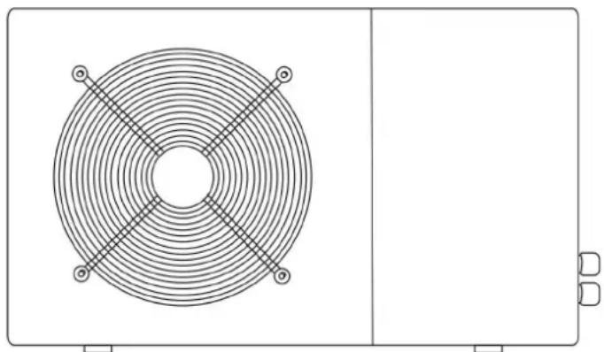
Swimming Pool Heat Pump
User and Service manual
natural_image
Technical line drawing of a circular fan component with four crosshair handles, mounted on a rectangular base (no text or symbols)English • French • Dutch • German • Polish • Danish
INDEX
CO2 Regulation (EU) P2\~P7
ENGLISH P8\~P34
FRENCH P35\~P63
DUTCH P64\~P90
GERMAN P91\~P119
POLISH P120\~P148
DANISH P149\~P176
Regulation (EU) n° 517/2014 of 16/04/14 on fluorinated greenhouse gases and repealing Regulation (EC) n° 842/2006
Leak checks
- Operators of equipment that contains fluorinated greenhouses gases in quantities of 5 tons of CO_2 , equivalent or more and not contained in foams shall ensure that the equipment is checked for leaks.
- For equipment that contains fluorinated greenhouse gases in quantities of 5 tons of CO_2 equivalent or more, but of less than 50 tons of _2 equivalent: at least every 12 months.
Picture of the equivalence 60
- Load in kg and Tons amounting. CO
| Load and Tons amounting ₽O | Frequency of test |
| From 2 at 30 kg load = from 5 at 50 Tons | Each year |
Concerning the Gaz R 410a, 2.39kg amounting at 5 tons _2 of cddomitment to check each year.
Training and certification
- The operator of the relevant application shall ensure that the relevant personnel have obtained the necessary certification, which implies appropriate knowledge of the applicable regulations and standards as well as the necessary competence in emission prevention and recovery of fluorinated greenhouse gases and handling safety the relevant type and size of equipment.
Record keeping
- Operators of equipment which is required to be checked for leaks, shall establish and maintain records for each piece of such equipment specifying the following information:
a) The quantity and type of fluorinated greenhouse gases installed;
b) The quantities of fluorinated greenhouse gases added during installation, maintenance or servicing or due to leakage;
c) Whether the quantities of installed fluorinated greenhouse gases have been recycled or reclaimed, including the name and address of the recycling or reclamation facility and, where applicable, the certificate number;
d) The quantity of fluorinated greenhouse gases recovered
e) The identity of the undertaking which installed, serviced, maintained and where applicable repaired or decommissioned the equipment, including, where applicable, the number of its certificate;
f) The dates and results of the checks carried out; g) If the equipment was decommissioned, the measures taken to recover and dispose of the fluorinated greenhouse gases.
- The operator shall keep the records for at least five years, undertakings carrying out the activities for operators shall keep copies of the records for at least five years.
Formation et certification
hydro-pro inverter Swimming Pool Heat Pump User and Service manual
INDEX
- Specifications
- Dimension
- Installation and connection
- Accessories
- Electrical Wiring
- Display Controller Operation
- Troubleshooting
- Exploded Diagram
- Maintenance
- Warranty and returns
Thank you for using hydro-pro inverter swimming pool heat pump for your pool heating, it will heat your pool water and keep the constant temperature when the air ambient temperature is at -10 to 50°C

ATTENTION: This manual includes all the necessary information with the use and the installation of
heat pump.
The installer must read the manual and attentively follow the instructions in implementation and maintain. The installer is responsible for the installation of the product and should follow all the instructions of the manufacturer and the regulations in application. Incorrect installation against the manual implies the exclusive the entire guarantee.
The manufacturer declines any responsibility for the damage caused with the people, objects and of the er to the installation that disobey the manual guideline. Any use that is without conformity at the origin of its manufacturing will be regarded as dangerous.
WARNING: Please always empty the water in heat pump during winter time or when the ambient temperature drops below 0^ C, or else the Titanium exchanger will be damaged because of being frozen, in such case, your warranty will be lost.
WARNING: Please always cut the power supply if you want to open the cabinet to reach inside the heat pump, because there is high voltage electricity inside.
WARNING: Please well keep the display controller in a dry area, or well close the insulation cover to protect the display controller from being damaged by humidity.
1. Specifications
1.1 Technical data hydro-pro inverter pool heat pumps
| Model | Inverter 07 | Inverter 10 | Inverter 13 | Inverter 17 | Inverter 21 | |
| Item No. | 7018545 | 7018546 | 7018547 | 7018548 | 7018549 | |
| * Performance at Air 27, Water 26C, Humidity 80% | ||||||
| Heating capacity | kW | 7-3.6 | 10-2.3 | 13-2.6 | 17-3.8 | 20-4 |
| Power consumption | kW | 1.06-0.3 | 1.52-0.18 | 1.94-0.2 | 2.54-0.29 | 2.98-0.3 |
| C.O.P. | 12-6.6 | 13-6.6 | 13-6.7 | 13-6.7 | 13-6.7 | |
| * Performance at Air 15, Water 26C, Humidity 70% | ||||||
| Heating capacity | kW | 5.1-2.5 | 7.1-1.9 | 9.6-2 | 11.5-3 | 14-3 |
| Power consumption | kW | 1-0.38 | 1.4-0.25 | 1.84-0.27 | 2.2-0.37 | 2.7-0.37 |
| C.O.P. | 6.5-5.1 | 7.5-5.1 | 7.5-5.2 | 8.2-5.2 | 8.2-5.1 | |
| * Performance at Air 35, Water 27C, Humidity 40% | ||||||
| Cooling capacity | kW | 3.6-1.68 | 5.0-1.21 | 6.6-1.4 | 8.3-2.0 | 9.7-2.06 |
| Power consumption | kW | 1.25-0.44 | 1.75-0.28 | 2.3-0.31 | 2.88-0.42 | 3.68-0.4 |
| E.E.R. | 3.78-2.88 | 4.25-2.88 | 4.49-2.88 | 4.73-2.88 | 5.11-2.64 | |
| Rated water flux | m^3/h | 2.50 | 3.00 | 4.00 | 5.00 | 6.00 |
| Fan power input | w | 5-20 | 8-40 | 8-40 | 10-50 | 10-50 |
| Voltage | 220~240V/50Hz/1PH | |||||
| Maximum Current | A | 4.43 | 6.65 | 8.57 | 11.31 | 12.98 |
| Minimum Fuse Current | A | 12 | 18 | 24 | 31 | 36 |
| Water in-out connection | mm | 50 | ||||
| Fan quantity | 1 | 1 | 1 | 1 | 1 | |
| Ventilation type | Horizontal | Horizontal | Horizontal | Horizontal | Horizontal | |
| Compressor brand | GMCC | GMCC | MITSUBISHI | MITSUBISHI | MITSUBISHI | |
| Noise level at 1m | dB(A) | 40-50 | 40-52 | 40-54 | 41-56 | 41-56 |
| Net dimension | mm | 1008*380*577 | 1050*440*709 | 1050*450*870 | ||
| Net weight | Kg | 54 | 68 | 78 | 98 | 108 |
| Packing dimension | mm | 1095*430*705 | 1130*470*850 | 1140*480*1010 | ||
| Gross Weight | Kg | 66 | 73 | 83 | 113 | 123 |
* Above data are subjects to modification without notice.
1.2 Technical data hydro-pro inverter pool heat pumps
| Model | Inverter 26 | Inverter 26T | Inverter 35 | Inverter 35T | |
| Item No. | 7018550 | 7018551 | 7018552 | 7018553 | |
| * Performance at Air 27, Water 26C, Humidity 80% | |||||
| Heating capacity | kW | 26-6.8 | 26-6.8 | 35-7 | 35-7 |
| Power consumption | kW | 3.88-0.52 | 3.88-0.52 | 5.22-0.54 | 5.22-0.54 |
| C.O.P. | 13-6.7 | 13-6.7 | 13-6.7 | 13-6.7 | |
| * Performance at Air 15, Water 26C, Humidity 70% | |||||
| Heating capacity | kW | 19-5.4 | 19-5.4 | 24-5.6 | 24-5.6 |
| Power consumption | kW | 3.6-0.66 | 3.6-0.66 | 4.8-0.68 | 4.8-0.68 |
| C.O.P. | 8.2-5.2 | 8.2-5.2 | 8.2-5 | 8.2-5 | |
| * Performance at Air 35, Water 27C, Humidity 40% | |||||
| Cooling capacity | kW | 13.0-3.48 | 13.0-3.48 | 17.3-3.8 | 17.3-3.8 |
| Power consumption | kW | 4.5-0.76 | 4.5-0.76 | 7.5-0.76 | 7.5-0.76 |
| E.E.R. | 4.55-2.88 | 4.55-2.88 | 5.02-2.3 | 5.02-2.3 | |
| Rated water flux | m^3/h | 8.00 | 8.00 | 10.00 | 10.00 |
| Fan power input | w | 8-40 | 8-40 | 8-40 | 8-40 |
| Voltage | 220~240V/50Hz/1PH | 380V/50Hz/3PH | 220~240V/50Hz/1PH | 380V/50Hz/3PH | |
| Maximum Current | A | 17.07 | 11.43 | 23.08 | 15.46 |
| Minimum Fuse Current | A | 47 | 31 | 63 | 43 |
| Water in-out connection | mm | 50 | |||
| Fan quantity | 2 | 2 | 2 | 2 | |
| Ventilation type | Horizontal | Horizontal | Horizontal | Horizontal | |
| Compressor brand | MITSUBISHI | MITSUBISHI | MITSUBISHI | MITSUBISHI | |
| Noise level at 1m | dB(A) | 42-60 | 42-60 | 42-60 | 42-60 |
| Net dimension | mm | 1050*452*1295 | |||
| Net weight | Kg | 120 | 120 | 130 | 130 |
| Packing dimension | mm | 1130*515*1430 | |||
| Gross Weight | Kg | 138 | 138 | 148 | 148 |
* Above data are subjects to modification without notice.
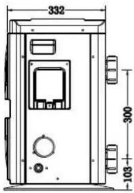
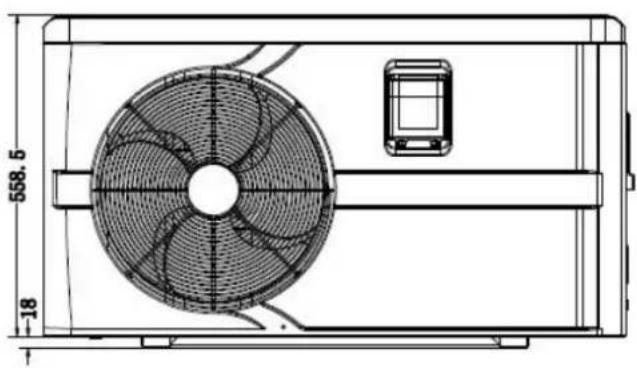
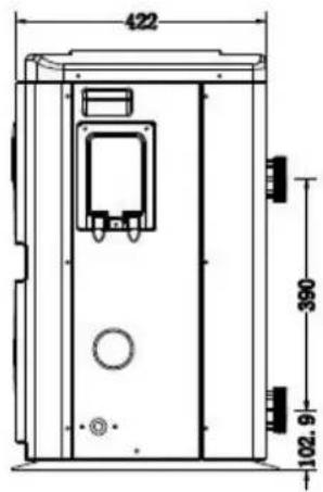
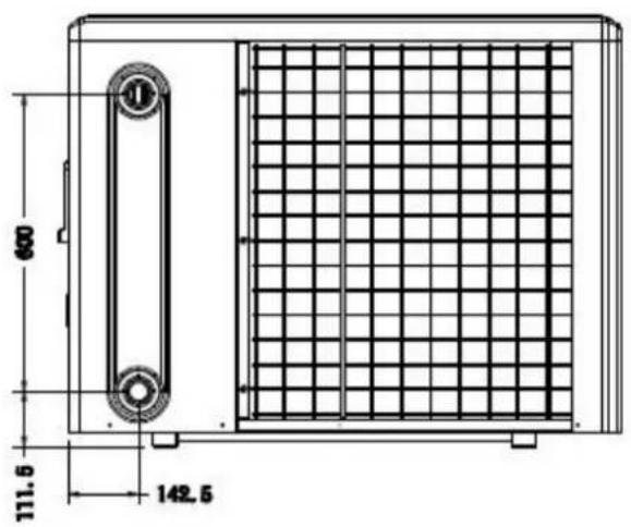
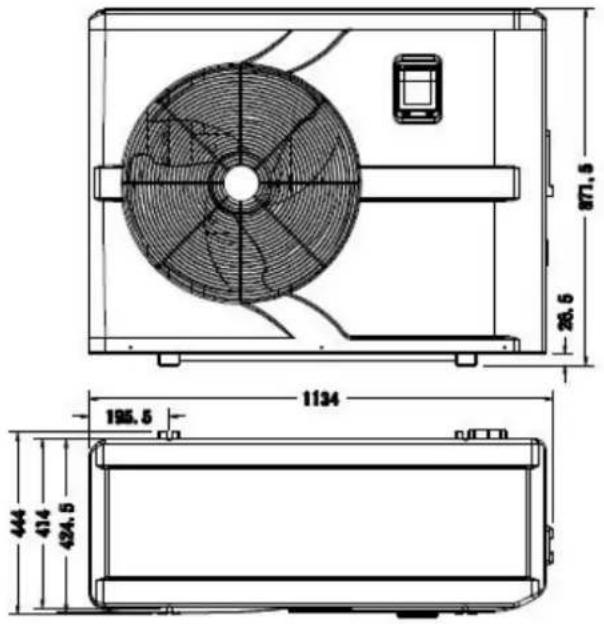
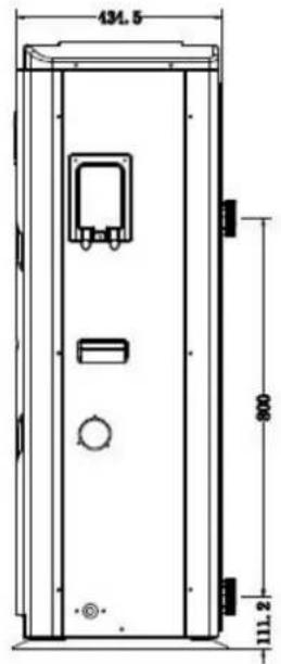
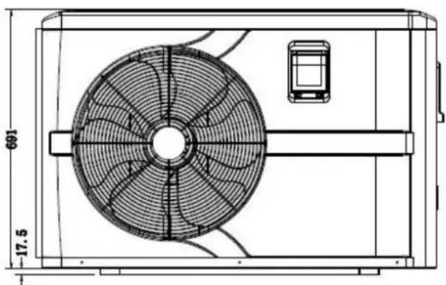
2. Dimension (mm)
Model Inverter 7
natural_image
Technical line drawing of a fan-shaped industrial device with dimension annotations (no readable text or symbols)
Model Inverter 10/13

natural_image
Technical line drawing of a fan or fan assembly with dimension annotations (691 and 17.5), no readable text or symbols beyond measurement lines.
Model Inverter 17/21


Model Inverter 26/26T/35/35T

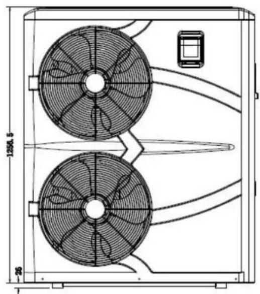
natural_image
Technical line drawing of a dual fan HVAC unit with fan blades and ventilation ducts (no text or symbols)
3. Installation and connection
3.1 Notes
The factory supplies only the heat pump. All other components, including a bypass if necessary, must be provided by the user or the installer.
Attention:
Please observe the following rules when installing the heat pump:
- Any addition of chemicals must take place in the piping located downstream from the heat pump.
- Install a bypass if the water flow from the swimming pool pump is more than 20% greater than the allowable flow through the heat exchanger of the heat pump.
- Always place the heat pump on a solid foundation and use the included rubber mounts to avoid vibration and noise.
- Always hold the heat pump upright. If the unit has been held at an angle, wait at least 24 hours before starting the heat pump.
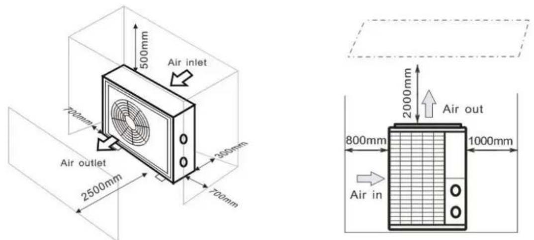
3.2 Heat pump location
The unit will work properly in any desired location as long as the following three items are present:
1. Fresh air - 2. Electricity - 3. Swimming pool filters
The unit may be installed in virtually any outdoor location as long as the specified minimum distances to other objects are maintained (see drawing below). Please consult your installer for installation with an indoor pool. Installation in a windy location does not present any problem at all, unlike the situation with a gas heater (including pilot flame problems).
ATTENTION: Never install the unit in a closed room with a limited air volume in which the air expelled from the unit will be reused, or close to shrubbery that could block the air inlet. Such locations impair the continuous supply of fresh air, resulting in reduced efficiency and possibly preventing sufficient heat output. See the drawing below for minimum dimensions.
3.3 Distance from your swimming pool
The heat pump is normally installed within a perimeter area extending 7.5 m from the swimming pool. The greater the distance from the pool, the greater the heat loss in the pipes. As the pipes are mostly underground, the heat loss is low for distances up to 30 m (15 m from and to the pump; 30 m in total) unless the ground is wet or the groundwater level is high. A rough estimate of the heat loss per 30 m is 0.6 kWh (2,000 BTU) for every 5 °C
difference between the water temperature in the pool and the temperature of the soil surrounding the pipe. This increases the operating time by 3% to 5%.
3.4 Check-valve installation
Note: If automatic dosing equipment for chlorine and acidity (pH) is used, it is essential to protect the heat pump against excessively high chemical concentrations which may corrode the heat exchanger. For this reason, equipment of this sort must always be fitted in the piping on the downstream side of the heat pump, and it is recommended to install a check-valve to prevent reverse flow in the absence of water circulation.
Damage to the heat pump caused by failure to observe this instruction is not covered by the warranty.
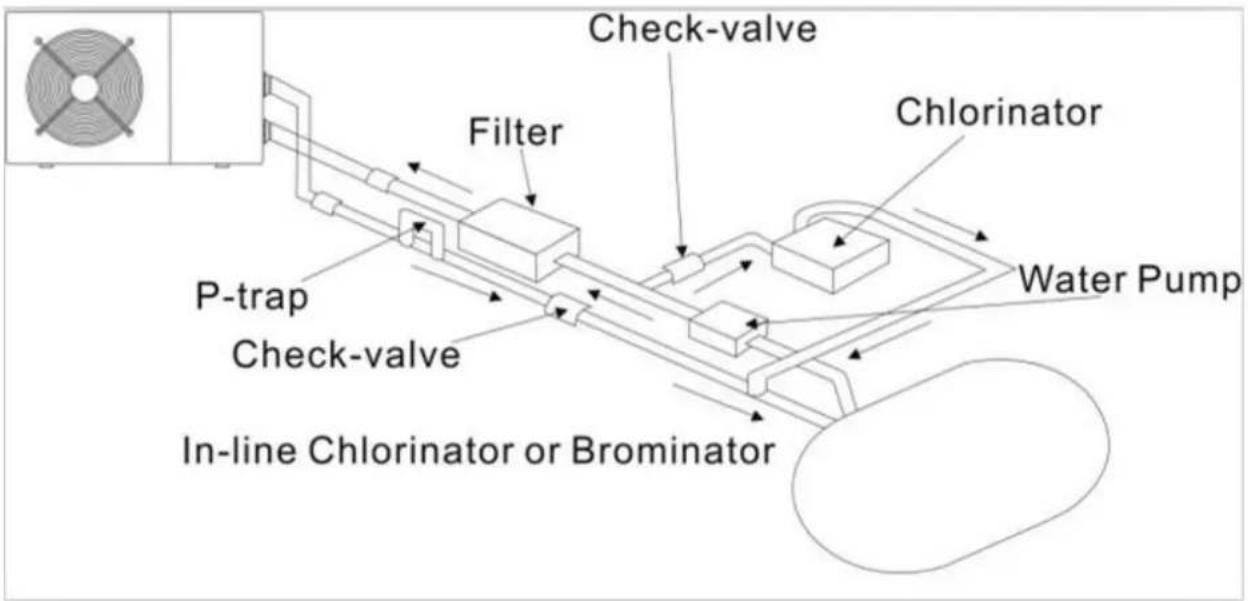
flowchart
graph LR
    A["In-line Chlorinator or Brominator"] --> B["P-trap"]
    B --> C["Check-valve"]
    C --> D["Filter"]
    D --> E["Check-valve"]
    E --> F["Chlorinator"]
    F --> G["Water Pump"]
    style A fill:#f9f,stroke:#333
    style G fill:#ccf,stroke:#333
3.5 Typical arrangement
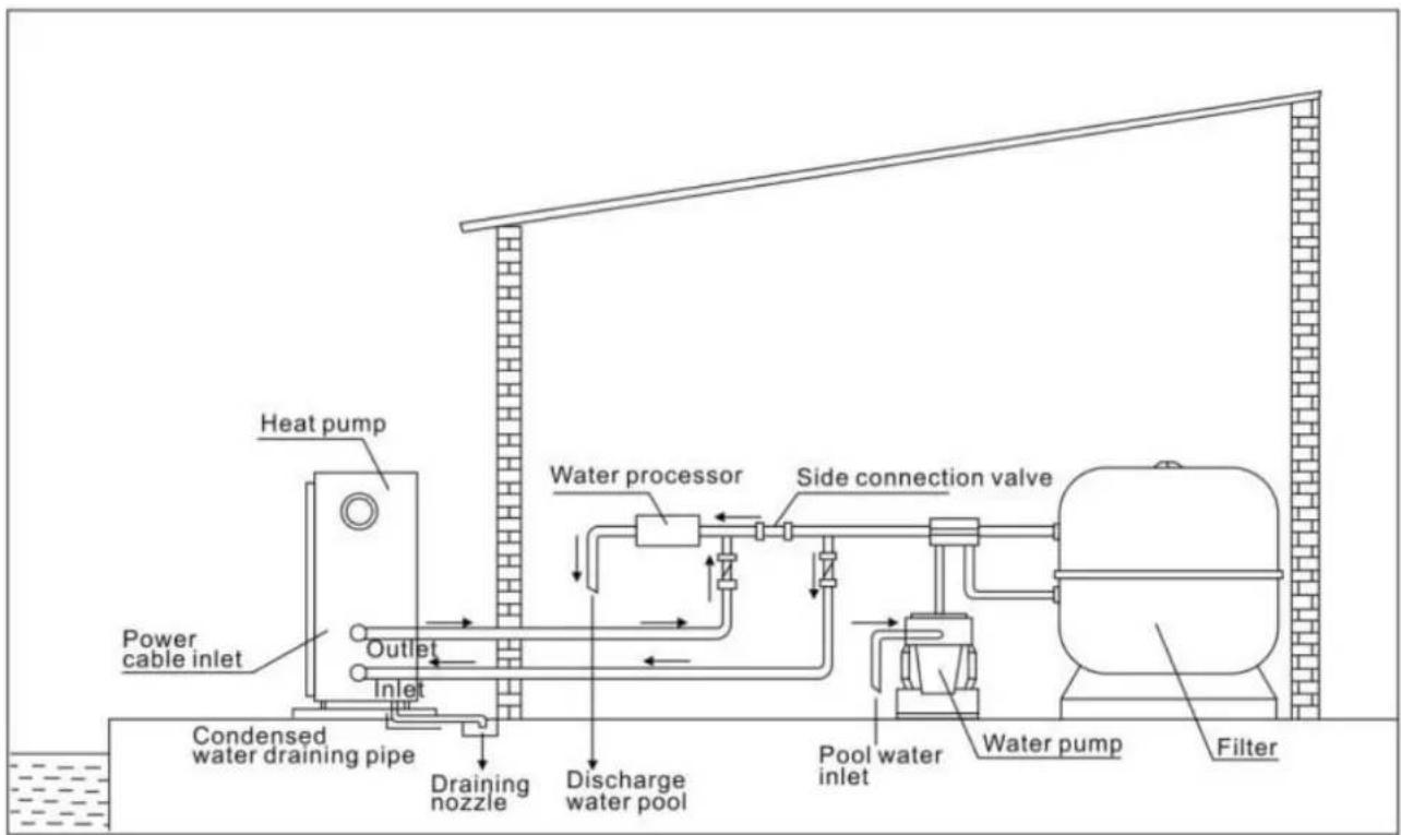
Note: This arrangement is only an illustrative example.
3.6 Adjusting the bypass
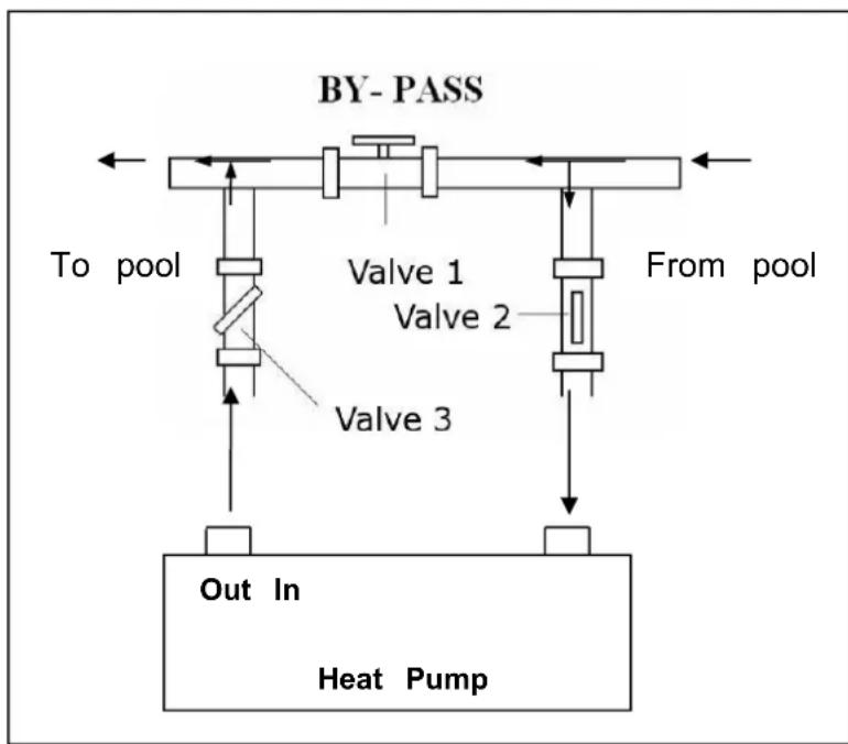
flowchart
graph TD
    A["To pool"] --> B["Valve 1"]
    B --> C["Valve 2"]
    C --> D["Valve 3"]
    D --> E["Out In Heat Pump"]
    F["From pool"] --> G["By-PASS"]
    style A fill:#f9f,stroke:#333
    style F fill:#f9f,stroke:#333
    style G fill:#f9f,stroke:#333
Use the following procedure to adjust the bypass:
• fully open all three valves
- slowly close valve 1 until the water pressure is increased by approximately 100 to 200g
- Close valve 3 approximately half-way to adjust the gas pressure in the cooling system
- If the display shows "ON" or error code EE3, close step step the valve 2, to increase water flow and stop when t code disappear.
Optimal operation of the heat pump occurs when the cooling gas pressure is 2
This pressure can be read on the pressure gauge next to the control heat pump panel. Under these conditions the water flow through the unit is also optimal.
Note: Operation without a bypass or with improper bypass adjustment may result in sub-optimal heat pump operation and possibly damage to the heat pump, which renders the warranty null and void.
3.7 Electrical connection
Note: Although the heat pump is electrically isolated from the rest of the swimming pool system, this only prevents the flow of electrical current to or from the water in the pool. Earthing is still required for protection against short-circuits inside the unit. Always provide a good earth connection.
Before connecting the unit, verify that the supply voltage matches the operating voltage of the heat pump.
It is recommended to connect the heat pump to a circuit with its own fuse or circuit breaker (slow type; curve D) and to use adequate wiring.
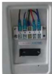
Connect the electrical wires to the terminal block marked 'POWER SUPPLY'.
A second terminal block marked 'WATER PUMP' is located next to the first one. The filter pump (max. 5 A / 240) can be connected to the second terminal block here. This allows the filter pump operation to be controlled by the heat pump.
Note: In the case of three-phase models, swapping two phases may cause the electric motors to run in the reverse direction, which can lead to damage. For this reason, the unit has a built-in protective device that breaks the circuit if the connection is not correct. If the red LED above this safety device lights up, you must swap the connections of
two of the phase wires.
3.8 Initial operation
Note: In order to heat the water in the pool (or hot tub), the filter pump must be running to cause the water to circulate through the heat pump. The heat pump will not start up if the water is not circulating.
After all connections have been made and checked, carry out the following procedure:
-
Switch on the filter pump. Check for leaks and verify that water is flowing from and to the swimming pool.
-
Connect power to the heat pump and press the On/Off button on the electronic control panel. The unit will start up after the time delay expires.
- After a few minutes, check whether the air blowing out of the unit is cooler.
- When turn off the filter pump, the unit should also turn off automatically, if not, then adjust the flow switch.
Depending on the initial temperature of the water in the swimming pool and the air temperature, it may take several days to heat the water to the desired temperature. A good swimming pool cover can dramatically reduce the required length of time.
Water Flow Switch:
It is equipped with a flow switch for protecting the HP unit running with adequate water flow rate. It will turn on the pool pump runs and shut it off when the pump shuts off. If the pool water level higher than 1 m above or below the heat pump's automatic adjustment knob, your dealer may need to adjust its initial startup.
Time delay - The heat pump has a built-in 3-minute start-up delay to protect the circuitry and avoid excessive contact wear. The unit will restart automatically after this time delay expires. Even a brief power interruption will trigger this time delay and prevent the unit from restarting immediately. Additional power interruptions during this delay period do not affect the 3-minute duration of the delay.
3.9 Condensation
The air drawn into the heat pump is strongly cooled by the operation of the heat pump for heating the pool water which may cause condensation on the fins of the evaporator. The amount of condensation may be as much as several litres per hour at high relative humidity. This is sometimes mistakenly regarded as a water leak.
3.10 Operating modes for optimal use
- POWER: Used primarily at the beginning of the season because this mode allows very rapid temperature rise
- SMART: The heat pump has completed its primary task, in this mode; the heat pump is in a position to maintain the pool water in an energy efficient manner. By automatically adjusting speed of compressor and fan the heat pump delivers a better return.
- SILENT: In the summer months when the heat output is minimal required, the heat pump in this mode is even more profitable. Added benefit; when the heat pump heats. It goes with minimal noise load.
4. Accessories
4.1 Accessories list
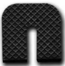 Anti-vibration base, 4 pcs Anti-vibration base, 4 pcs | 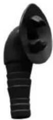 Draining jet, 2 pcs Draining jet, 2 pcs | 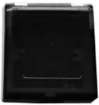 Waterproof box, 1 pc Waterproof box, 1 pc |
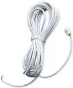 10M Signal wire, 1 pc 10M Signal wire, 1 pc | 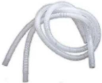 Water drainage pipes, 2 pcs Water drainage pipes, 2 pcs |
4.2 Accessories Installation
natural_image
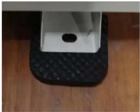
Top-down view of a black textured square stepping on a wooden floor, with a small circular hole and a white rectangular block above (no text or symbols visible)Anti-vibration bases
- Take out 4 Anti-vibration bases
- Put them one by one on the bottom machine like the picture.
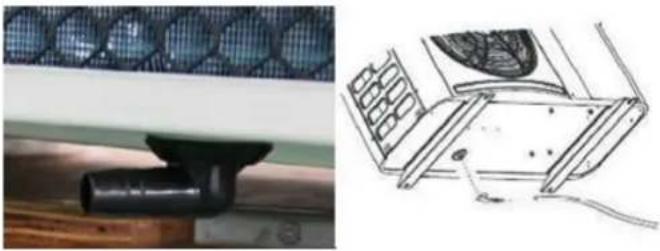 | Draining jet1. Install the draining jet under the bottom panel2. Connect with a water pipe to drain the water.Note: Lift the heat pump to install the jet. Never overturn the heat pump, it could damage the compressor. |
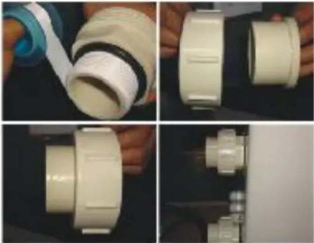 | Water Inlet & outlet junction1. Use the pipe tape to connect the water Inlet & outlet junction onto the heat pump2. Install the two joints like the picture shows3. Screw them onto the water Inlet & outlet junction |
 | Cable wiring1. Connect the power supply wire through the white hole like the picture shows.2. Fix the other side on joints inside the electric box. |
 | Water pump wiring1. Connect the water pump wire through the white hole marked2. Fix the other side on joints inside the electric box. |
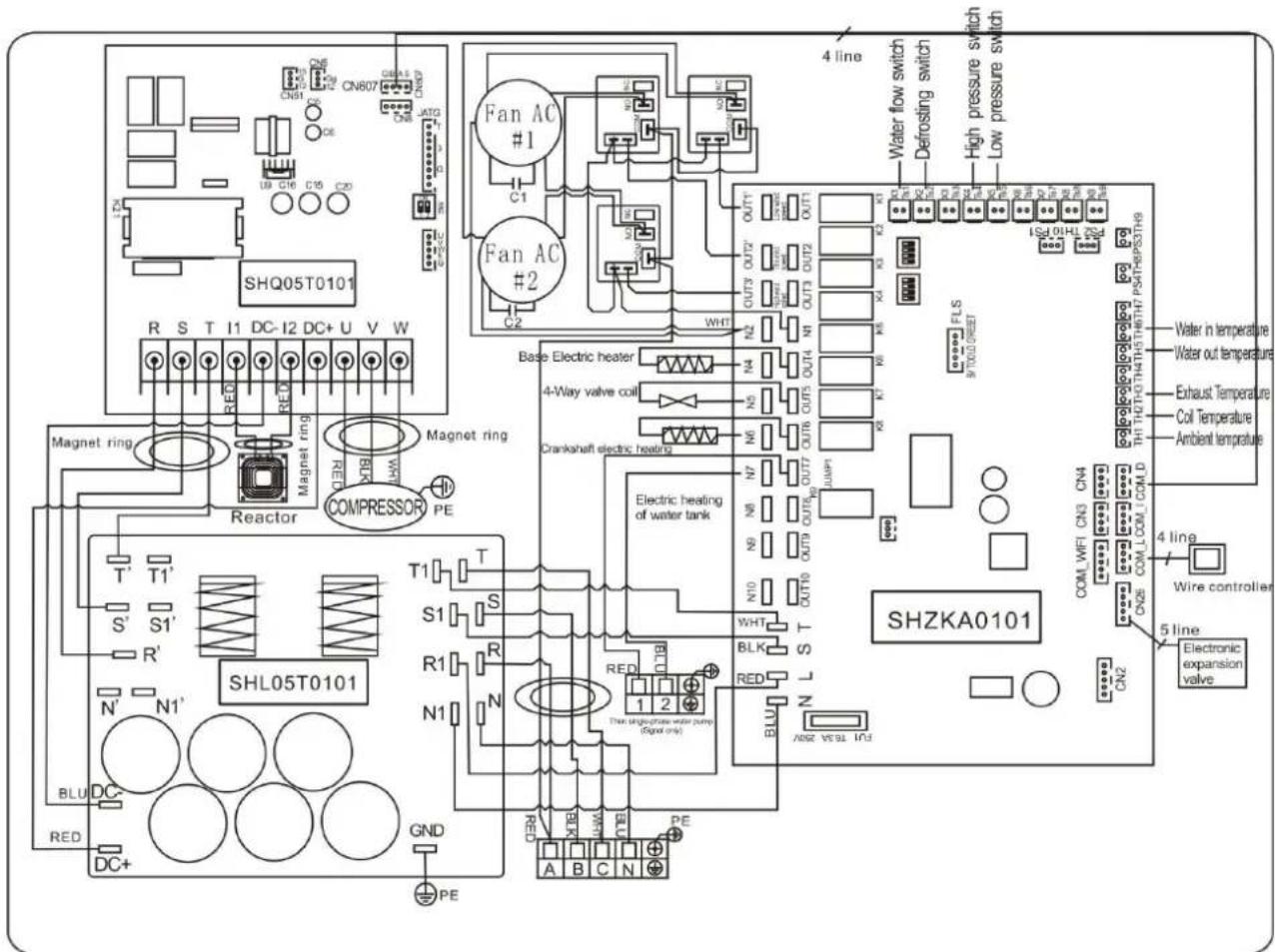
5. Electrical Wiring
5.1 SWIMMING POOL HEAT PUMP WIRING DIADRAM
Inverter 7/10/13/17/21
flowchart
graph TD
    A["Reactor"] --> B["Magnet ring"]
    B --> C["RED"]
    C --> D["I1"]
    D --> E["Magnet ring"]
    E --> F["FAN2"]
    F --> G["OUT9"]
    G --> H["4-Way valve coil"]
    H --> I["N6"]
    I --> J["OUT6"]
    J --> K["N5"]
    K --> L["N4"]
    L --> M["Base Electric heater"]
    M --> N["N3"]
    N --> O["OUT3"]
    O --> P["N2"]
    P --> Q["N1"]
    Q --> R["OUT2"]
    R --> S["OUT1"]
    S --> T["N9"]
    T --> U["EEPROM Burning interface"]
    U --> V["COM"]
    V --> W["OUT10"]
    W --> X["NO"]
    X --> Y["AC-N"]
    Y --> Z["AC-L"]
    Z --> AA["COM1"]
    AA --> AB["COM2"]
    AB --> AC["Ts1 Ts2 Ts3 Ts4 Ts5"]
    AC --> AD["Magnet ring"]
    AD --> AE["BLU"]
    AE --> AF["L N ⊕ 1 2"]
    AF --> AG["RED BLU"]
    AG --> AH["BRN L N ⊕ 1 2"]
    AH --> AI["220V~50Hz Pump"]
    AJ["Magnet ring"] --> AK["W"]
    AK --> AL["V"]
    AL --> AM["U"]
    AM --> AN["Magnet ring"]
    AN --> AO["BLK WHT"]
    AO --> AP["Electronic Expansion Valve"]
    AP --> AQ["Ambient temperature Coil Temperature"]
    AQ --> AR["Ehaust Temperature Water out temperature"]
    AR --> AS["Water in temperature"]
    AS --> AT["Wire controller"]
    AT --> AU["Defrosting switch Water flow switch"]
    AU --> AV["High pressure switch Low pressure switch"]
    AV --> AW["BRN BRN L N ⊕ 1 2"]
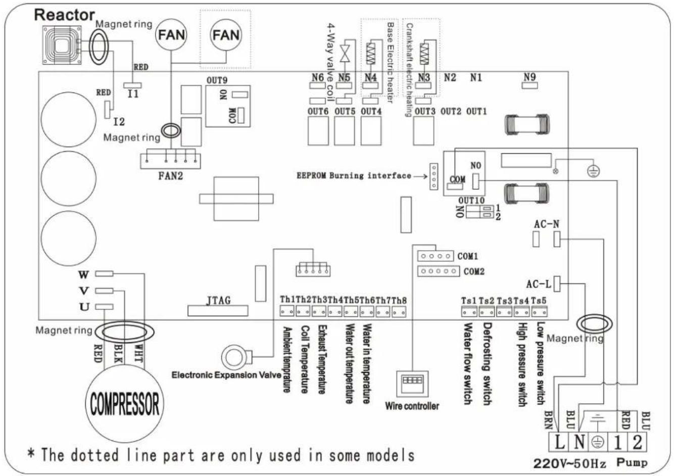
5.2 SWIMMING POOL HEAT PUMP WIRING DIADRAM
Inverter 26/35
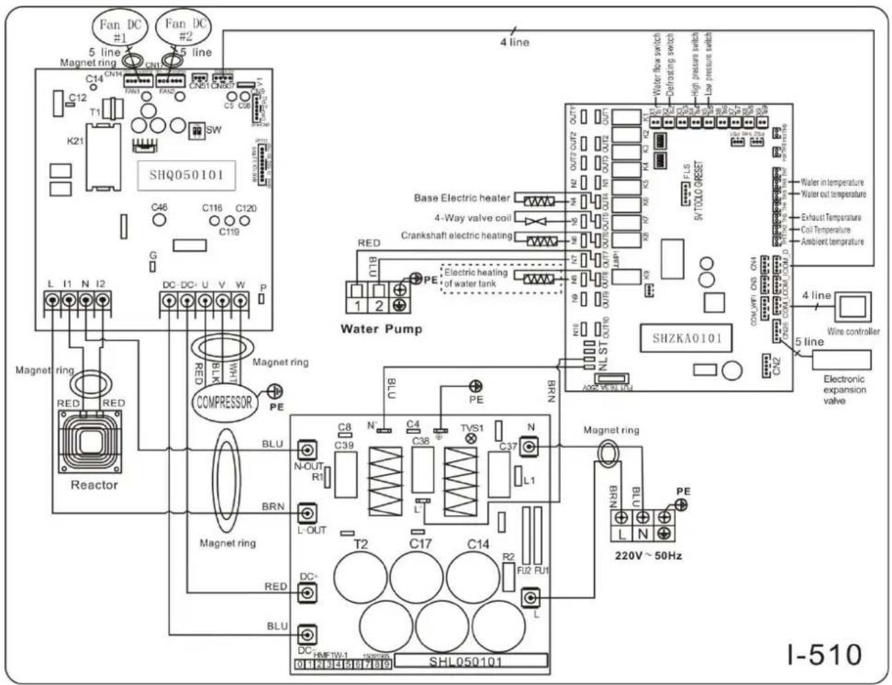
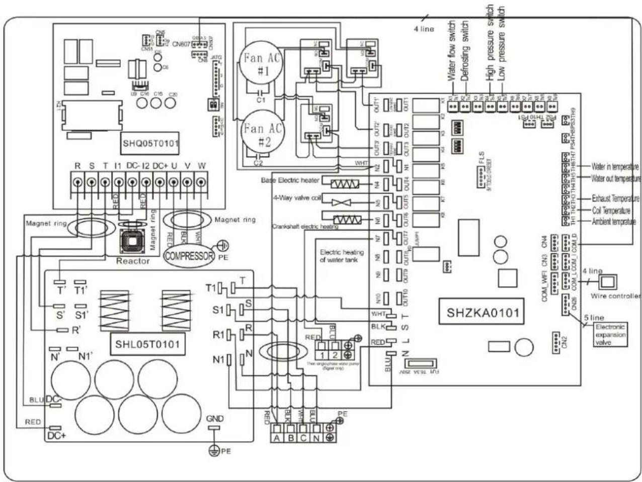
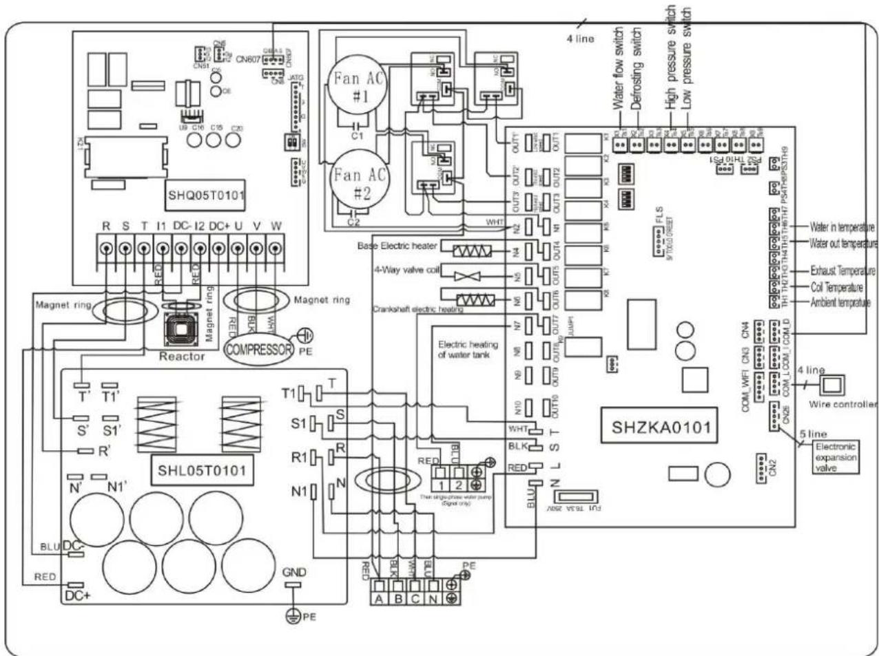
5.3 SWIMMING POOL HEAT PUMP WIRING DIADRAM
Inverter 26T/35T
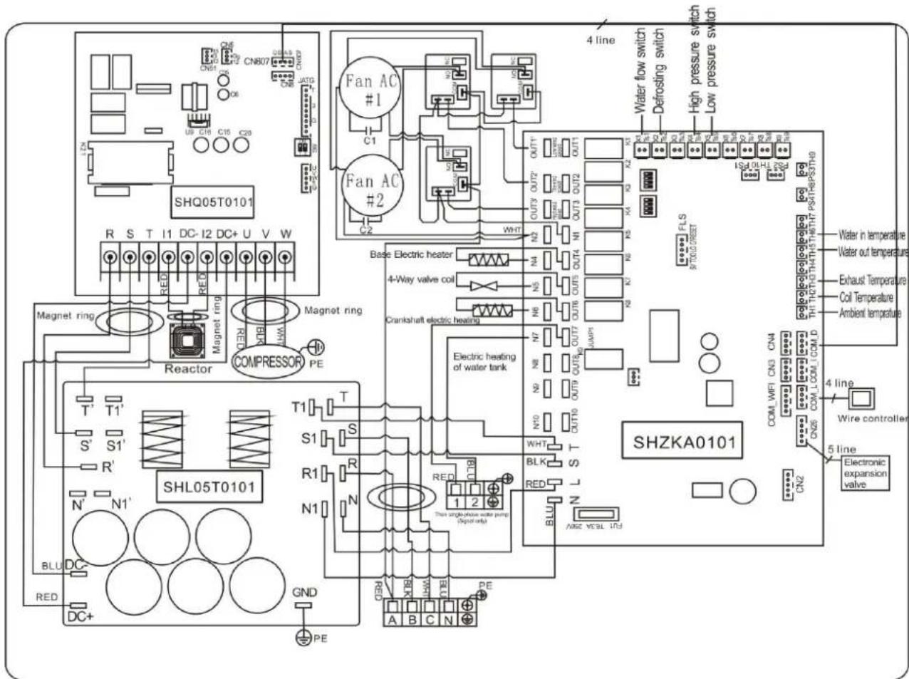
NOTE:
(1)Above electrical wiring diagram only for your reference, please subject machine posted the wiring diagram. (2)The swimming pool heat pump must be connected ground wire well, although the unit heat exchanger is electrically isolated from the rest of the unit .Grounding the unit is still required to protect you against short circuits inside the unit .Bonding is also required.
Disconnect: A disconnect means (circuit breaker, fused or un-fused switch) should be located within sight of and readily accessible from the unit. This is common practice on commercial and residential heat pumps. It prevents remotely-energizing unattended equipment and permits turning off power at the unit while the unit is being serviced.
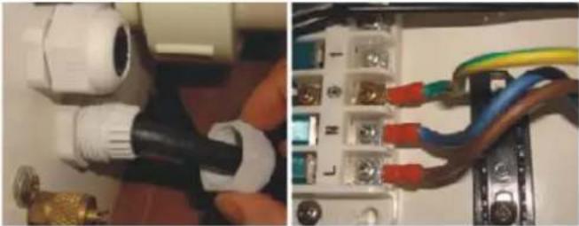
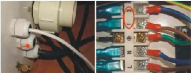
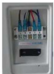
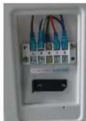
5.4 Installation of the display deportee
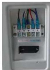
Photo(1) Photo(2) Photo(3) Photo(4) Photo(5)

natural_image
Close-up of a white electronic device with coiled cable and probe inserted, placed on dark surface (no visible text or symbols)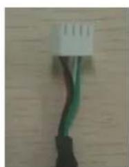
natural_image
Close-up of a black cable with green wires against a wooden background (no text or symbols visible)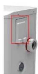
natural_image
Close-up of a white electrical outlet with multiple blue and red cables, no visible text or symbols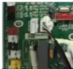
natural_image
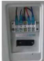
Close-up of a green printed circuit board with visible traces and components (no readable text or symbols)- The side with plug connects with the control panel (photo1)
- The other side of the signal wire. (photo2)
- Open the wiring panel and put the side without plug through the electrical box. (photo3,4)
- Insert the wiring into the disignated position (upper right corner) on the PC board. (photo5)
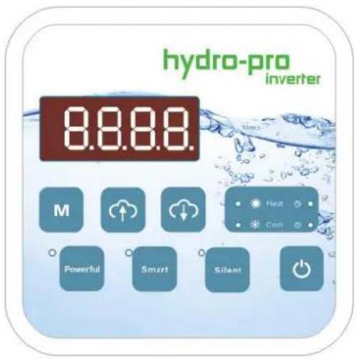
6. Display Controller Operation
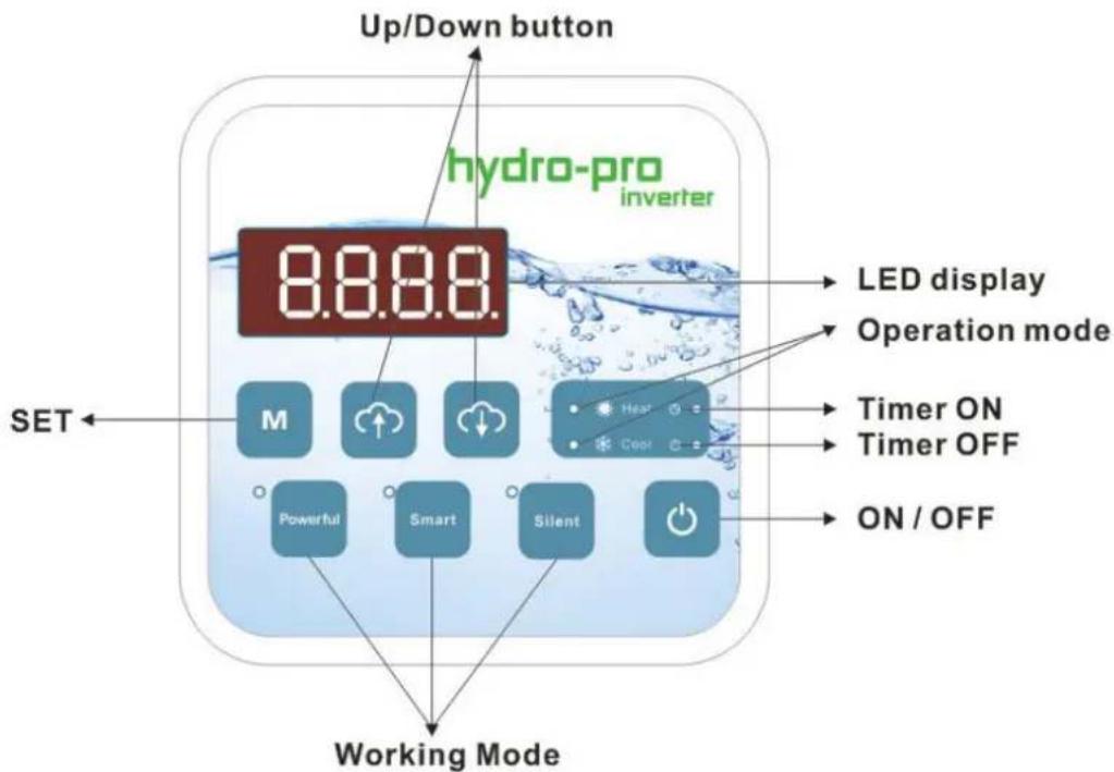
6.1 The buttons of LED wire controller
6.2 The keys and their operations
6.2.1 button
Press ☐ to start the heat pump unit, the LED display shows the desired water temperature for 5 seconds, then shows the inlet water temperature and the operation mode.
Press to stop the heat pump unit and show "OFF"
Notice : During the parameter checking and setting, press the to quick-exit and save the current setting .
Press again to turn on/off the machine.
6.2.2 button
It will be under function only with other button.
6.2.3 and button
Clock/unclock the display:
Hold and for 5 seconds to lock/Unlock the display.
Water temperature setting :
Press or to set the water temperature directly.
Parameter checking :
Press first, then press to check the "User parameter from d0 to d11
| Code | Condition | Scope | Remark |
| d0 | IPM mould temperature | 0-120°C | Real testing value |
| d1 | Inlet water temp. | -9°C~99°C | Real testing value |
| d2 | Outlet water temp. | -9°C~99°C | Real testing value |
| d3 | Ambient temp. | -30°C~70°C | Real testing value |
| d4 | Return gas temp. | -30°C~70°C | Real testing value |
| d5 | Piping temp. | -30°C~70°C | Real testing value |
| d6 | Gas exhaust temperature | 0°C~C5°C (125°C) | Real testing value |
| d7 | Step of EEV | 0~99 | N*5 |
| d8 | Compressor running frequency | 0~99Hz | Real testing value |
| d9 | Compressor current | 0~30A | Real testing value |
| d10 | Current fan speed | 0-1200 (rpm) | Real testing value |
| d11 | Error code for last time | All error code |
Press first, then press to check/adjust the "User parameter from P1 to P7
| Code | Name | Scope | Default | Remard |
| P1 | Working mode | 0-1 | 1 | 1 Heating mode 0 cooling mode |
| P2 | Timer on/off | 0-1 | 0 | 1 Timer on/off is under function, 0 Timer on/off is out of function (The setting of P4 and P5 won't work) |
| P3 | Water pump | 0-1 | 0 | 1 Always running 0 Depends on the running of compressor |
| P4 | Current time | HH:MM | 00: 00 | 0-23:0-59 |
| P5 | Timer on | HH:MM | 00: 00 | 0-23:0-59 |
| P6 | Timer off | HH:MM | 00: 00 | 0-23:0-59 |
| P7 | Inlet water temp. correction | -9~9 | 0 | Default setting: 0 |
6.2.4 System reset function
Press and in 10s, the system will reset and display "0000" on the controller.
6.2.5 Heat
Symbol of heating, the light will be on when it is in operation.
When defrosting, the light will flash.
6.2.6

Symbol of cooling, the light will be on when it is in operation.
6.2.7

Symbol of automatic stop, the light will be on when it is in operation.
6.2.8

Symbol of automatic start, the light will be on when it is in operation.
6.2.9

Press this button, the light will be flash, the heat pump will operate in 'Full output' only..
6.2.10

While you choose the Smart, the heat pump will just operate in 'Medium output' and 'Full output'
When in 'Medium output', the light of Smart will flash.
When in 'Full output', the lamp of Smart is lighting, the lamp of Powerful will be flash.
6.2.11

While you choose the Silent, the heat pump will just operate in 'Medium output' and 'Small output'. When in 'Small output', the light of Silent will flash.
When in 'Medium output', the lamp of Silent is lighting, the lamp of Smart will be flash.
7. Troubleshooting
7.1 Error code display on LED wire controller
| Malfunction | Error code | Reason | Solution |
| Inlet water temperature sensor failure | PP01 | The sensor in open or short circuit | Check or change the sensor |
| Outlet water temperature sensor failure | PP02 | The sensor in open or short circuit | Check or change the sensor |
| Heating condenser sensor failure | PP03 | The sensor in open or short circuit | Check or change the sensor |
| Gas return sensor failure | PP04 | The sensor in open or short circuit | Check or change the sensor |
| Ambient temperature sensor failure | PP05 | The sensor in open or short circuit | Check or change the sensor |
| Condenser gas exit sensor failure | PP06 | The sensor in open or short circuit | Check or change the sensor |
| Antifreeze protection in Winter | PP07 | Ambient temperature or water inlet temperature is too low | |
| Low ambient temperature protection | PP08 | Ambient temperature or water inlet temperature is too low | |
| Cooling condenser temperature too high protection | PP10 | Cooling condenser temperature is too high | Stop the heat pump and wait the cooling condenser temperature drop down |
| T2 water temp. Too low protection under cooling mode | PP11 | 1. Water pump failure2. Water piping blocked3. Water flow switch seized | |
| High pressure failure | EE01 | 1. Refrigerant is too much2. Air flow is not enough | 1. Discharge redundant refrigerant from HP gas system2. Clean the air exchanger |
| Low pressure failure | EE02 | 1. Refrigerant is not enough2. Water flow is not enough3. Filter jammed or capillary jammed | 1. Check if there is any gas leakage, re-fill the refrigerant2. Clean the air exchanger3. Replace the filter or capillary |
| Water flow failure | EE03 | Low water flow, wrong flow direction, or flow switch failure. | Check if the water flow is enough and flow in right direction, or el the flow switch could be failed. |
| Malfunction | Error code | Reason | Solution |
| Overheating in heating mode | EE04 | Low or No water flow | Failure of water pumpWater pipe jammedFailure of water flow switch |
| Gas exhaust temperature sens failure | EE05 | Defrosting is not goodLack of gasThe throttling device is jammedLow water flow | Defrosting by handPlus, the gasChange the throttling deviceCheck the water pump |
| Controller failure | EE06 | Wire connection is not goodController failure | Check or change the signal wireRestart the power supply or change the controller |
| Converter failure | EE07 | Converter board failure | Restart the power supply or change the converter board |
| Communication failure between controller and converter board | EE08 | Wire connection is not goodController failure | Check or change the wire connectionRestart the power supply or change the controller |
| Communication failure between converter and outdoor board | EE09 | Wire connection between communication wire and outdoor board is wrongOutdoor board failure | RewiringRestart the power supply or change the outdoor board |
| module board failure between outdoor board and module board | EE10 | Communication wire is brokeOutdoor board or module board failure | Restart the power supply or change the broken board |
| Module board failure | EE11 | The data is wrong or the module board is broken | Restart the power supply or change the broken board |
| Direct main current's voltage too high or too low protect | EE12 | The pressure is too high or lowThe inner communication contactor is broken | Check the power supplyChange the contactor |
| Over current protection | EE13 | Electric supply pressure is to low, the heat pump is over | Check the power supplyCheck the water temperature whether it is too high |
| IPM module temperature sensing circuit output failure | EE14 | IPM module temperature sensor output is abnormal | Check the PC board or replace the new one |
| IPM module temperature too high protection | EE15 | Check the PC board or replace the new one |
| Malfunction | Error code | Reason | Solution |
| PFC module protection | EE16 | Check the PC board or replace the new one | |
| DC fan failure | EE17 | Check the PC board or replace the new one | |
| PFC module temperature sensing internal circuit failure | EE18 | Check the PC board or replace the new one | |
| PFC module high temperature protection | EE19 | Check the PC board or replace the new one | |
| Input power failure | EE20 | The supply voltage fluctuates too much | Check the PC board or replace the new one |
| Software control failure | EE21 | Compressor runs out of s | Check the PC board or replace the new one |
| Current detection circuit failure | EE22 | The amplifier output voltage signal is abnormal | Check the PC board or replace the new one |
| Compressor start failure | EE23 | Check the PC board or replace the new one | |
| Driving board ambient temperature bulb failure | EE24 | ||
| Compressor phase failure | EE25 | 1. Wiring wrong2. Connection of 1 phase 2 phases. | Monitoring the controller |
7.2 Other Malfunctions and Solutions (No display on LED wire controller)
| Malfunctions | Observing | Reasons | Solution |
| Heat pump is not running | LED wire controller no display. | No power supply | Check cable and circuit breaker if it is connected |
| LED wire controller. displays the actual time. | Heat pump under standby status | Startup heat pump to run. | |
| LED wire controller displays the actual water temperature. | 1. Water temperature is reaching to setting value, HF under constant temperature status.2. Heat pump just starts to run.3. Under defrosting. | 1. Verify water temperature setting.2. Startup heat pump after a few minutes.3. LED wire controller should display "Defrosting". | |
| Water temperature is cooling when HP runs under heating mode | LED wire controller displays actual water temperature and no error code displays. | 1. Choose the wrong mode.2. Figures show defects.3. Controller defect. | 1. Adjust the mode to proper running2. Replace the defect LED wire controller, and then check the status after changing the running mode, verifying the water inlet and outlet temperature.3. Replace or repair the heat pump unit |
| Short running | LED displays actual water temperature, no error code displays. | 1. Fan NO running.2. Air ventilation is not enough.3. Refrigerant is not enough | 1. Check the cable connection between the motor and fan, necessary, it should be replaced.2. Check the location of heat pump unit, and eliminate all obstacles to make good air ventilation.3. Replace or repair the heat pump unit. |
| water stains | Water stains on heat pump unit. | 1. Concreting.2. Water leakage. | 1. No action.2. Check the titanium heat exchanger carefully if it is any defect. |
| Too much ice or evaporator | Too much ice on evaporator. | 1. Check the location of heat pump unit, and eliminate all obstacles to make good air ventilation.2. Replace or repair the heat pump unit. |
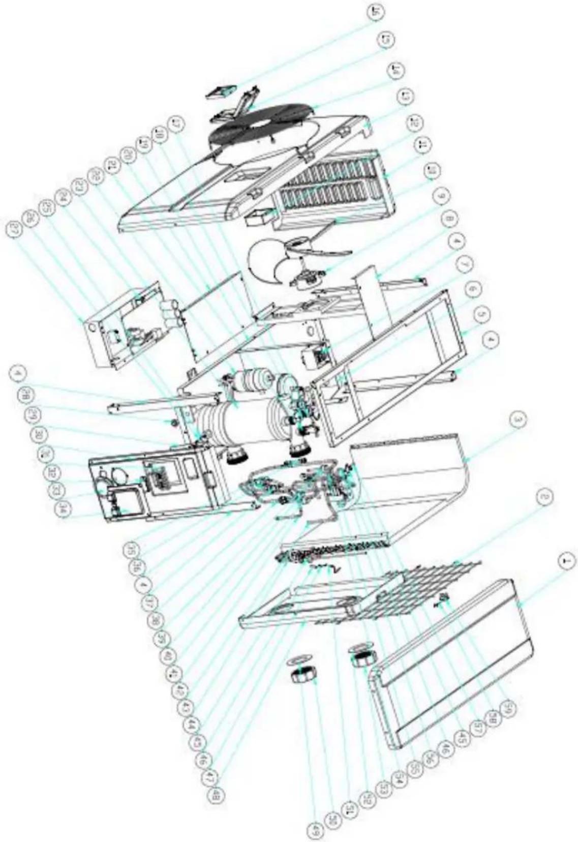
8. Exploded Diagram and Maintenance
8. 1 Exploded Diagram
Model 7 kw
| NO | Part Name | NO | Part Name |
| 1 | Top cover | 31 | Terminal |
| 2 | Back grill | 32 | Wiring clip |
| 3 | Evaporator | 33 | Pressure gauge |
| 4 | Pillar | 34 | Wiring cover |
| 5 | Top frame | 35 | Needle valve |
| 6 | Isolation panel | 36 | EEV |
| 7 | Reactor | 37 | Piping |
| 8 | Motor bracket | 38 | Return pipe |
| 9 | Motor | 39 | High pressure switch |
| 10 | Fan blade | 40 | Low pressure switch |
| 11 | Left side panel | 41 | Low pressure switch |
| 12 | Wiring box | 42 | Expansion valve to the distributor |
| 13 | Front panel | 43 | 4-way valve to collective pipe |
| 14 | Front grill | 44 | Collective assembly |
| 15 | Waterproof box | 45 | Distributor assembly |
| 16 | Controller | 46 | Temperature casing |
| 17 | Outlet water temperature sensor TH5 | 47 | temperature sensor casing |
| 18 | Exchanger temp. sensor fixed film | 48 | Back panel |
| 19 | Base tray | 49 | Blue rubber |
| 20 | Electric box cover | 50 | Water supply screw cover |
| 21 | Water flow switch | 51 | Coil temperature sensor TH2 |
| 22 | compressor | 52 | Red rubber |
| 23 | Titanium exchanger | 53 | Water supply screw cover |
| 24 | Main board | 54 | 4-way valve to exchanger |
| 25 | Exchanger temp. sensor fixed film | 55 | 4-way valve |
| 26 | Water inlet temperature sensor TH6 | 56 | exhaust pipe |
| 27 | Electric box | 57 | Exhaust air temperature sensor TH3 |
| 28 | Drainage plug | 58 | Ambient temperature sensor TH1 |
| 29 | Wiring box | 59 | Ambient temperature temperature clip |
| 30 | Right side panel |
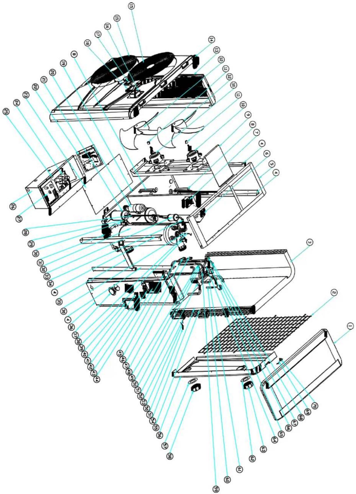
| NO | Part Name | NO | Part Name |
| 1 | Top cover | 36 | Right side panel |
| 2 | Back grill | 37 | Pressure gauge |
| 3 | Evaporator | 38 | Outlet water temperature sensor TH5 |
| 4 | Pillar | 39 | Water flow switch |
| 5 | Top frame | 40 | Wiring cover |
| 6 | Isolation panel | 41 | Wiring clip |
| 7 | Reactor | 42 | 3-terminal for water pump |
| 8 | Panel support frame | 43 | 3-terminal power supply |
| 9 | Motor bracket | 44 | Terminal board bracket |
| 10 | Motor | 45 | Terminal board |
| 11 | DC motor casing | 46 | Return pipe |
| 12 | Fan blade | 47 | Low pressure switch |
| 13 | Left side panel | 48 | Low pressure switch |
| 14 | Front panel | 49 | Exhaust air temperature sensor TH3 |
| 15 | Front grill | 50 | temperature sensor casing |
| 16 | Wiring box | 51 | Temperature casing |
| 17 | Controller | 52 | 4-way valve to collective pipe |
| 18 | Waterproof box | 53 | Coil temperature sensor TH2 |
| 19 | Base tray | 54 | Collective assembly |
| 20 | compressor | 55 | Distributor assembly |
| 21 | Storage tank | 56 | Back panel |
| 22 | Driver board | 57 | Blue rubber |
| 23 | Electric box cover | 58 | Water supply screw cover |
| 24 | Filter plate | 59 | Reservoir to expansion valve |
| 25 | Lining | 60 | Expansion valve to the distributor |
| 26 | Electric box | 61 | 4-way valve to exchanger |
| 27 | Main board | 62 | Red rubber |
| 28 | Filter to reservoir | 63 | Water supply screw cover |
| 29 | Water inlet temperature sensor TH6 | 64 | Needle valve |
| 30 | Exchanger temp. sensor fixed film | 65 | 4-way valve |
| 31 | Drainage plug | 66 | EEV |
| 32 | Titanium exchanger | 67 | High pressure switch |
| 33 | filter | 68 | exhaust pipe |
| 34 | Exchanger to filter | 69 | Ambient temperature sensor TH1 |
| 35 | Hand pumping support board | 70 | Ambient temperature temperature clip |
9. Maintenance
(1) You should check the water supply system regularly to avoid the air entering the system and occurrence of low water flow, because it would reduce the performance and reliability of HP unit.
(2) Clean your pools and filtration system regularly to avoid the damage of the unit as a result of the dirty of clogged filter.
(3) You should discharge the water from bottom of water pump if HP unit will stop running for a long time (special during the winter season).
(4) In another way, you should check the unit is water fully before the unit start to run again.
(5) After the unit is conditioned for the winter season, he is preconize to cover the heat pump with special winter heat pump.
(6) When the unit is running, there is all the time a little water discharge under the unit.
10. Warranty and returns
10.1 Warranty
LIMITED WARRANTY
Thank you for purchasing a heat pump from us.
This warranty covers manufacturing and material defects in all components for a period of two years a date of purchase.
This warranty is limited to the original purchaser in the retail sector. It is not transferable, and it is not applicable to products that have been removed from their original installation location. The liability of the manufacturer is limited to the repair or replacement of defective components and does not include the labour for removing and replacing the defective component(s), the cost of transporting component(s) from to the factory, or costs associated with other materials necessary for carrying out repairs. This warranty not cover any defects attributable to the following causes:
- Installation, operation or maintenance of the product other than in accordance with the guidelines and/or instructions in the Installation and Operation Manual supplied with the product.
- Faulty or deficient work performed on the product by an installer.
- Failure to maintain the correct chemical balance in the swimming pool [pH between 7.0 and 7.8; total alkalinity (TA) between 80 and 150 ppm; free chlorine concentration between 0.5 and 1.2 mg/l; total dissolved solids (TDS) less than 1,200 ppm; maximum salt concentration 8 g/l].
- Improper use, modification, accident, fire, flood, lighting strike, rodents, insects, negligence, neglect, or force majeure.
- Deposits, freezing, or other conditions that impair proper water flow through the product.
- Operating the product with a flow rate outside the published minimum and maximum specifications.
- Use of components or accessories not designed or made for this product.
- Chemical contamination of the air used by the product or improper use of decontaminating chemicals such as the addition of decontaminating chemicals through the skimmer or in the pipes or lines located upstream of the heat pump and the cleaning hose.
- Overheating, improper electrical connections, improper power supply, secondary damage attributable to defective O-rings, diatomaceous filters or filter cartridges, or damage caused by putting the pump in operation in the absence of sufficient water.
LIMITATIONS ON LIABILITY
This is the sole warranty provided by the manufacturer. Nobody is authorised to grant other warranties name.
THIS WARRANTY REPLACES ALL OTHER EXPLICITLY GRANTED OR IMPLICIT WARRANTIES, INCLUDING BU NOT LIMITED TO ANY FORM OF IMPLICIT WARRANTY OF SUITABILITY FOR A PARTICULAR PURPOSE OF FITNESS FOR SALE. WE EXPLICITLY DISAVOW ANY LIABILITY FOR INDIRECT, INCIDENTAL OR CONSEQUENTIAL LOSS OR DAMAGE OF A PUNITIVE NATURE RESULTING FROM THE VIOLATION OF AN EXPLICITLY GRAN IMPLICIT WARRANTY.
This warranty gives you specific legal rights, which may vary depending on the country.
WARRANTY CLAIMS
To ensure prompt handling of your warranty claim, please contact your dealer and provide the following information to the dealer: proof of purchase, model number, serial number and date of installation. The installer will contact the factory to obtain instructions regarding the procedure for making warranty claim to find out the location of the closest service centre.
All returned components must be marked with a RMA number so that it can be determined whether they are covered by the warranty.
10.2 RMA request form
| Company: | Date: | |||||
| Street address: | ||||||
| City/town: | Postal code: | Country: | ||||
| Contact: | Phone: | |||||
| E-mail: | Fax: | |||||
| Contact: | Date: |
| Reserved for internal use | |||
| RMA no.: | |||
| Assigned by: | Date: | ||
Reason for return: Copy of customer invoice included?

| RMA request accompanied by other documents?□ | |
| Description of the documents: | |
| Model no.: | Invoice no.: | ||
| Serial number: | Invoice date: | ||
| Problem: | |||
Warranty repair policy
- Shipping costs for returned products must be paid in advance. All shipping costs associated with a return shipment are borne by you.
- Products may be sent back to us only after prior approval by the company. Return shipments for which approval has not been given by the company will be sent back, with all shipping costs to be borne by you.
- We will replace or repair the products and return them to you free of charge using the shipping service of your choice.
- If you choose express shipment (by a shipping service selected by you), you are responsible for paying the shipping costs.
Return procedure
- Before requesting an RMA number from us, please check whether you have properly observed the installation and use instructions in the manual.
- Contact our RMA department by phone and ask for an RMA request form.
- Ensure that all fields of the RMA request form are fully completed.
- In the case of returns during the warranty period, please include the customer copy of your original sales invoice.
- Send the RMA request form, the sales invoice and any other relevant documents (photos, etc.) to us or provide them by e-mail. An RMA number will be assigned to you within 24 hours after we receive the necessary documents. We may refuse to assign you an RMA number if the information mentioned in points 3 and 4 above is missing.
-
The RMA number must be marked clearly on the shipping label of the package and noted on the shipping documents.
-
All products received by us that lack labels or that have incorrect, incomplete or unreadable labels will be refused, with return shipping costs to be borne by you.
- All packages delivered to us with clearly visible damage will be refused immediately.
- Before returning products, please check that the products you intend to return to us are the same as the products for which an RMA number was issued. If the received products do not match the products registered under the assigned RMA number, we will return all of the products at your expense.
-
No return shipments at all will be accepted without an RMA number. Absolutely no exceptions to this rule are allowed.
-
An RMA number remains valid for just 21 calendar days after it is assigned. We reserve the right to refuse to accept products returned to us if they are received more than 21 days after the date when the RMA number was assigned.
Products not covered or no longer covered by the warranty
The customer is responsible for paying shipping and repair costs. The estimated repair costs will be advised after the problem(s) with the returned products have been diagnosed.
The minimum charge of a diagnosis is €50.00.
MegaGroup Trade Holding BV
Doornhoek 4205 - 5465 TG Veghel - The Netherlands
P.O. Box 430 - 5460 AK Veghel
- The Netherlands
www.megagrouptrade.com
hydro-pro inverter
natural_image
Technical line drawing of a fan-shaped industrial device with dimension annotations (no readable text or symbols)
Model Inverter 10/13


natural_image
Technical line drawing of a fan or fan assembly with dimension annotations (691 and 17.5), no readable text or symbols beyond measurement lines.
Model Inverter 17/21

Model Inverter 26/26T/35/35T


natural_image
Technical line drawing of a dual fan HVAC unit with fan blades and ventilation ducts (no text or symbols)
3. Installation et connection
3.1 Note
5.3 SCHEMA DE CABLAGE DE LA POMPE À CHALEUR DE PISCINE
Inverter 26T/35T
NOTE:
natural_image
Close-up of a white electronic device with coiled wires on a dark surface (no visible text or symbols)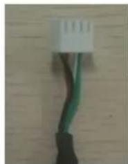
natural_image
Close-up of a black and green cable with a white connector on a wooden surface (no text or symbols visible)
natural_image
Close-up of a white electrical terminal panel with multiple colored wires and a black connector (no visible text or symbols)
natural_image
Close-up of a green printed circuit board with visible components and wiring (no readable text or symbols)FAIRE VALOIR LA GARANTIE
natural_image
Technical line drawing of a fan-shaped industrial device with dimension annotations (no readable text or symbols)
Model Inverter 10/13


natural_image
Technical line drawing of a fan or vent system with internal blades and a small inset device, shown without any text or symbols.
Model Inverter 17/21

Model Inverter 26/26T/35/35T

natural_image
Technical line drawing of a dual fan HVAC unit with fan blades and ventilation ducts (no text or symbols)
natural_image
Close-up of a white electronic device with coiled cable and connector (no visible text or symbols)
natural_image
Close-up of a black cable with green wires and a white connector (no text or symbols visible)
natural_image
Close-up of a white electrical outlet with multiple colored cables and connectors (no visible text or symbols)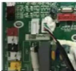
natural_image
Close-up of a green printed circuit board with visible traces and components (no readable text or symbols)MegaGroup Trade Holding BV
natural_image
Technical line drawing of a fan-shaped industrial device with dimension annotations (no readable text or symbols)
Model Inverter 10/13

natural_image
Technical line drawing of a fan or vent system with internal blades and a small inset device, shown without any text or symbols.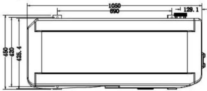
Model Inverter 17/21


Model Inverter 26/26T/35/35T


natural_image
Technical line drawing of a dual fan HVAC unit with fan blades and ventilation ducts (no text or symbols)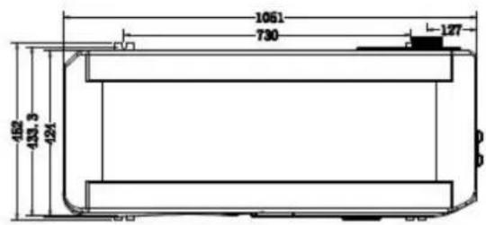
5.3 VERKABELUNGSDIAGRAMM DER SCHWIMMBECKEN-WÄRMEPUMPE
Inverter 26T/35T
HINWEIS:
natural_image
Close-up of a white electronic device with coiled wires on a dark surface (no visible text or symbols)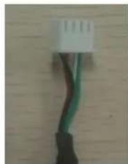
natural_image
Close-up of a black cable with green wires against a wooden background (no text or symbols visible)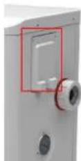
natural_image
Electrical outlet panel with multiple colored cables and a black connector (no visible text or symbols)
natural_image
Close-up of a green printed circuit board with visible traces and components (no readable text or symbols)Modell 26 kw
natural_image
Technical line drawing of a fan-shaped industrial device with dimension annotations (no readable text or symbols)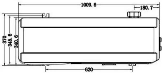
Model Inverter 10/13


natural_image
Technical line drawing of a fan or vent system with internal blades and a small inset device, shown without any text or symbols.
Model Inverter 17/21


Model Inverter 26/26T/35/35T


natural_image
Technical line drawing of a dual fan HVAC unit with fan blades and ventilation ducts (no text or symbols)
natural_image
Close-up of a white rectangular object with a small black hole on a dark textured base, placed on a wooden floor (no text or symbols visible)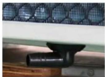
natural_image
Close-up of a black pipe fitting attached to a wooden surface next to a mesh-patterned panel (no text or symbols visible)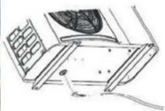
natural_image
Technical line drawing of a mechanical assembly with no visible text or symbolsnatural_image
Close-up of a white electronic device with coiled wires on a dark surface (no visible text or symbols)
natural_image
Close-up of a black cable with green wires against a wooden background (no text or symbols visible)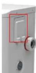
natural_image
Close-up of a white electrical outlet with multiple blue and red wires connected to numbered connectors (no visible text or symbols)
natural_image
Close-up of a green printed circuit board with visible traces and components (no readable text or symbols)1.1 Technical data hydro-pro inverter pool varmepumper
| Model | Inverter 07 | Inverter 10 | Inverter 13 | Inverter 17 | Inverter 21 | |
| Item No. | 7018545 | 7018546 | 7018547 | 7018548 | 7018549 | |
| * Performance at Air 27, Water 26C, Humidity 80% | ||||||
| Heating capacity | kW | 7-3.6 | 10-2.3 | 13-2.6 | 17-3.8 | 20-4 |
| Power consumption | kW | 1.06-0.3 | 1.52-0.18 | 1.94-0.2 | 2.54-0.29 | 2.98-0.3 |
| C.O.P. | 12-6.6 | 13-6.6 | 13-6.7 | 13-6.7 | 13-6.7 | |
| * Performance at Air 15, Water 26C, Humidity 70% | ||||||
| Heating capacity | kW | 5.1-2.5 | 7.1-1.9 | 9.6-2 | 11.5-3 | 14-3 |
| Power consumption | kW | 1-0.38 | 1.4-0.25 | 1.84-0.27 | 2.2-0.37 | 2.7-0.37 |
| C.O.P. | 6.5-5.1 | 7.5-5.1 | 7.5-5.2 | 8.2-5.2 | 8.2-5.1 | |
| * Performance at Air 35, Water 27C, Humidity 40% | ||||||
| Cooling capacity | kW | 3.6-1.68 | 5.0-1.21 | 6.6-1.4 | 8.3-2.0 | 9.7-2.06 |
| Power consumption | kW | 1.25-0.44 | 1.75-0.28 | 2.3-0.31 | 2.88-0.42 | 3.68-0.4 |
| E.E.R. | 3.78-2.88 | 4.25-2.88 | 4.49-2.88 | 4.73-2.88 | 5.11-2.64 | |
| Rated water flux | m^3/h | 2.50 | 3.00 | 4.00 | 5.00 | 6.00 |
| Fan power input | w | 5-20 | 8-40 | 8-40 | 10-50 | 10-50 |
| Voltage | 220~240V/50Hz/1PH | |||||
| Maximum Current | A | 4.43 | 6.65 | 8.57 | 11.31 | 12.98 |
| Minimum Fuse Current | A | 12 | 18 | 24 | 31 | 36 |
| Water in-out connection | mm | 50 | ||||
| Fan quantity | 1 | 1 | 1 | 1 | 1 | |
| Ventilation type | Horizontal | Horizontal | Horizontal | Horizontal | Horizontal | |
| Compressor brand | GMCC | GMCC | MITSUBISHI | MITSUBISHI | MITSUBISHI | |
| Noise level at 1m | dB(A) | 40-50 | 40-52 | 40-54 | 41-56 | 41-56 |
| Net dimension | mm | 1008*380*577 | 1050*440*709 | 1050*450*870 | ||
| Net weight | Kg | 54 | 68 | 78 | 98 | 108 |
| Packing dimension | mm | 1095*430*705 | 1130*470*850 | 1140*480*1010 | ||
| Gross Weight | Kg | 66 | 73 | 83 | 113 | 123 |
natural_image
Technical line drawing of a dual fan HVAC unit with fan blades and ventilation ducts (no text or symbols)
Optimal operation of the heat pump occurs when the cooling gas pressure is 2
natural_image
Close-up of a black textured square base with a small white object on top, placed on a wooden floor (no text or symbols visible)Vibrationsdæmpende baser
5.3 SWIMMINGPOOL VARMEPUMPE WIRING DIAGRAM
Inverter 26T/35T
NOTE:
natural_image
Close-up of a white electronic device with coiled cable and connector, placed on dark surface (no visible text or symbols)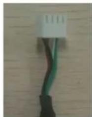
natural_image
Close-up of a black cable with green wires against a wooden background (no text or symbols visible)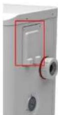
natural_image
Close-up of a white electrical outlet with multiple wires and connectors (no visible text or symbols)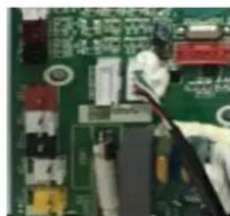
natural_image
Close-up of a green printed circuit board with visible traces and components (no readable text or symbols)6. Display Controller Operation
6.1 Knapperne ved LED wire-controller
10. Warranty and returns
10.1 Warranty
LIMITED WARRANTY
Thank you for purchasing a heat pump from us.
This warranty covers manufacturing and material defects in all components for a period of two years a date of purchase.
This warranty is limited to the original purchaser in the retail sector. It is not transferable, and it is not applicable to products that have been removed from their original installation location. The liability of the manufacturer is limited to the repair or replacement of defective components and does not include the labour for removing and replacing the defective component(s), the cost of transporting component(s) from to the factory, or costs associated with other materials necessary for carrying out repairs. This warranty not cover any defects attributable to the following causes:
- Installation, operation or maintenance of the product other than in accordance with the guidelines a instructions in the Installation and Operation Manual supplied with the product.
- Faulty or deficient work performed on the product by an installer.
- Failure to maintain the correct chemical balance in the swimming pool [pH between 7.0 and 7.8; total alkalinity (TA) between 80 and 150 ppm; free chlorine concentration between 0.5 and 1.2 mg/l; total dissolved solids (TDS) less than 1,200 ppm; maximum salt concentration 8 g/l].
- Improper use, modification, accident, fire, flood, lighting strike, rodents, insects, negligence, neglect, force majeure.
- Deposits, freezing, or other conditions that impair proper water flow through the product.
- Operating the product with a flow rate outside the published minimum and maximum specifications.
- Use of components or accessories not designed or made for this product.
- Chemical contamination of the air used by the product or improper use of decontaminating chemicals such as the addition of decontaminating chemicals through the skimmer or in the pipes or lines located upstream of the heat pump and the cleaning hose.
- Overheating, improper electrical connections, improper power supply, secondary damage attributable to defective O-rings, diatomaceous filters or filter cartridges, or damage caused by putting the pump into operation in the absence of sufficient water.
LIMITATIONS ON LIABILITY
This is the sole warranty provided by the manufacturer. Nobody is authorised to grant other warranties name.
THIS WARRANTY REPLACES ALL OTHER EXPLICITLY GRANTED OR IMPLICIT WARRANTIES, INCLUDING BU NOT LIMITED TO ANY FORM OF IMPLICIT WARRANTY OF SUITABILITY FOR A PARTICULAR PURPOSE OF FITNESS FOR SALE. WE EXPLICITLY DISAVOW ANY LIABILITY FOR INDIRECT, INCIDENTAL OR CONSEQUENTIAL LOSS OR DAMAGE OF A PUNITIVE NATURE RESULTING FROM THE VIOLATION OF AN EXPLICITLY GRAND IMPLICIT WARRANTY.
This warranty gives you specific legal rights, which may vary depending on the country.
WARRANTY CLAIMS
To ensure prompt handling of your warranty claim, please contact your dealer and provide the following information to the dealer: proof of purchase, model number, serial number and date of installation. The installer will contact the factory to obtain instructions regarding the procedure for making warranty claim to find out the location of the closest service centre.
All returned components must be marked with a RMA number so that it can be determined whether they are covered by the warranty.
10.2 RMA request form
| Company: | Date: | |||||
| Street address: | ||||||
| City/town: | Postal code: | Country: | ||||
| Contact: | Phone: | |||||
| E-mail: | Fax: | |||||
| Contact: | Date: |
| Reserved for internal use | |||
| RMA no.: | |||
| Assigned by: | Date: | ||
Reason for return: Copy of customer invoice included?

| RMA request accompanied by other documents?□ | |
| Description of the documents: | |
| Model no.: | Invoice no.: | ||
| Serial number: | Invoice date: | ||
| Problem: | |||
Warranty repair policy
- Shipping costs for returned products must be paid in advance. All shipping costs associated with a return shipment are borne by you.
- Products may be sent back to us only after prior approval by the company. Return shipments for which approval has not been given by the company will be sent back, with all shipping costs to be borne by you.
- We will replace or repair the products and return them to you free of charge using the shipping service of your choice.
- If you choose express shipment (by a shipping service selected by you), you are responsible for paying the shipping costs.
Return procedure
- Before requesting an RMA number from us, please check whether you have properly observed the installation and use instructions in the manual.
- Contact our RMA department by phone and ask for an RMA request form.
- Ensure that all fields of the RMA request form are fully completed.
- In the case of returns during the warranty period, please include the customer copy of your original sales invoice.
- Send the RMA request form, the sales invoice and any other relevant documents (photos, etc.) to us or provide them by e-mail. An RMA number will be assigned to you within 24 hours after we receive the necessary documents. We may refuse to assign you an RMA number if the information mentioned in points 3 and 4 above is missing.
-
The RMA number must be marked clearly on the shipping label of the package and noted on the shipping documents.
-
All products received by us that lack labels or that have incorrect, incomplete or unreadable labels will be refused, with return shipping costs to be borne by you.
- All packages delivered to us with clearly visible damage will be refused immediately.
- Before returning products, please check that the products you intend to return to us are the same as the products for which an RMA number was issued. If the received products do not match the products registered under the assigned RMA number, we will return all of the products at your expense.
- No return shipments at all will be accepted without an RMA number. Absolutely no exceptions to this rule are allowed.
- An RMA number remains valid for just 21 calendar days after it is assigned. We reserve the right to refuse to accept products returned to us if they are received more than 21 days after the date when the RMA number was assigned.
Products not covered or no longer covered by the warranty
The customer is responsible for paying shipping and repair costs. The estimated repair costs will be advised after the problem(s) with the returned products have been diagnosed.
The minimum charge of a diagnosis is €50.00.