22T - Water pump Hydro-Pro - Free user manual and instructions
Find the device manual for free 22T Hydro-Pro in PDF.

| Product type | Pool heat pump |
| Brand | Hydro-Pro |
| Model | 22T |
| Use | Heating and cooling of pool water |
| Heating capacity (Air 27°C / Water 27°C) | 22 kW (75,000 BTU/h) |
| Heating capacity (Air 15°C / Water 26°C) | 14.5 kW (49,500 BTU/h) |
| Cooling capacity (Air 35°C / Water 27°C) | 11 kW (37,500 BTU/h) |
| COP (Air 27°C / Water 27°C) | 5.9 |
| COP (Air 15°C / Water 26°C) | 4.2 |
| Power supply | 3 x 380 V / 50 Hz |
| Nominal current | 6.6 A |
| Recommended fuse | 20 A (curve D) |
| Wire cross-section (max 15 m) | 4 x 2.5 mm² + ground |
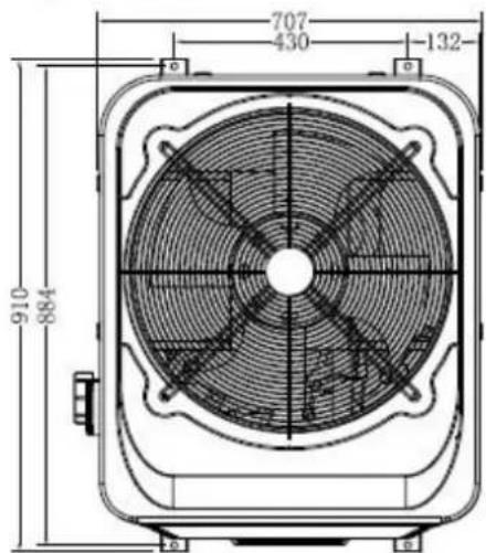
| Dimensions (L x W x H) | 910 x 707 x 940 mm |
| Net weight / Gross weight | 125 kg / 135 kg |
| Refrigerant | R410a |
| Compressor type | Scroll |
| Condenser | Titanium heat exchanger |
| Recommended water flow | 6.2 m³/h |
| Max pressure loss | 18 kPa |
| Inlet/outlet connection diameter | 50 mm |
| Sound level at 10 m / 1 m | 47 dB(A) / 56 dB(A) |
| Max pool volume (good insulation) | 120 m³ |
| Ambient temperature range | -5°C to 43°C |
| Controller | Remote electronic with LED display |
| Functions | Heating, cooling, timer, automatic mode |
| Protections | High pressure, low pressure, anti-freeze, flow switch |
| Maintenance | Check water circuit, clean evaporator, drain in winter |
| Warranty | 2 years limited (parts and labor) |
Frequently Asked Questions - 22T Hydro-Pro
User questions about 22T Hydro-Pro
0 question about this device. Answer the ones you know or ask your own.
Ask a new question about this device
Download the instructions for your Water pump in PDF format for free! Find your manual 22T - Hydro-Pro and take your electronic device back in hand. On this page are published all the documents necessary for the use of your device. 22T by Hydro-Pro.
USER MANUAL 22T Hydro-Pro
Swimming Pool Heat Pump
User and Service manual
English • French • Dutch • German • Russian • Polish
INDEX FOR DIFFERENT LANGUAGES
CO2 Regulation (EU) 2~8
English manual. 9~39
Regulation (EU) n° 517/2014 of 16/04/14 on fluorinated greenhouse gases and repealing Regulation (EC) n° 842/2006
Leak checks
- Operators of equipment that contains fluorinated greenhouses gases in quantities of 5 tons of CO_2 , equivalent or more and not contained in foams shall ensure that the equipment is checked for leaks.
- For equipment that contains fluorinated greenhouse gases in quantities of 5 tons of CO_2 equivalent or more, but of less than 50 tons of ^2 equivalent: at least every 12 months.
Picture of the equivalence 60
- Load in kg and Tons amounting.CO
| Load and Tons amounting ΣΟ | Frequency of test |
| From 2 at 30 kg load = from 5 at 50 Tons | Each year |
Concerning the Gaz R 410a, 2.39kg amounting at 5 tons 2 ofc 1 omitment to check each year.
Training and certification
- The operator of the relevant application shall ensure that the relevant personnel have obtained the necessary certification, which implies appropriate knowledge of the applicable regulations and standards as well as the necessary competence in emission prevention and recovery of fluorinated greenhouse gases and handling safety the relevant type and size of equipment.
Record keeping
- Operators of equipment which is required to be checked for leaks, shall establish and maintain records for each piece of such equipment specifying the following information:
a) The quantity and type of fluorinated greenhouse gases installed;
b) The quantities of fluorinated greenhouse gases added during installation, maintenance or servicing or due to leakage;
c) Whether the quantities of installed fluorinated greenhouse gases have been recycled or reclaimed, including the name and address of the recycling or reclamation facility and, where applicable, the certificate number;
d) The quantity of fluorinated greenhouse gases recovered
e) The identity of the undertaking which installed, serviced, maintained and where applicable repaired or decommissioned the equipment, including, where applicable, the number of its certificate;
f) The dates and results of the checks carried out;
g) If the equipment was decommissioned, the measures taken to recover and dispose of the fluorinated greenhouse gases.
- The operator shall keep the records for at least five years, undertakings carrying out the activities for operators shall keep copies of the records for at least five years.
Formation et certification
HYDRO-PRO Swimming Pool Heat Pump User and Service manual
INDEX
- Specifications
- Dimension
- Installation and connection
- Accessories
- Electrical Wiring
- Display Controller Operation
- Running data setting
- Troubleshooting
- Exploded Diagram
10.Maintenance
11.Warranty and returns
Thank you for using HYDRO-PRO swimming pool heat pump for your pool heating, it will help your pool water and keep the constant temperature when the air ambient temperature is to 43^
ATTENTION: This manual includes all the necessary information with the the installation of your heat pump.
The installer must read the manual and attentively follow the instructions in impl and maintenance.
The installer is responsible for the installation of the product and should follow instructions of the manufacturer and the regulations in application. Incorrect installation against the manual implies the exclusion of the entire guarantee.
The manufacturer declines any responsibility for the damage caused with the people and of the errors due to the installation that disobey the manual guideline. Any use without conformity at the origin of its manufacturing will be regarded as dangerous
WARNING: Please always empty the water in heat pump during winter time or when the ambient temperature drops below 0^ , or else the Titanium exchanger will be damaged because of being frozen, in such case, your warranty will be lost.
WARNING: Please always cut the power supply if you want to open the cabinet to read inside the heat pump, because there is high voltage electricity inside.
WARNING: Please well keep the display controller in a dry area, or well close the insulator cover to protect the display controller from being damaged by humidity.
1. Specification
Technical data Hydro-Pro heat pumps ABS
| Hydro-Pro | Model | 5 | 7 | 10 | 13 | 18 | 22 | 22T | 26 | 26T |
| Part number | 7018522 | 7018523 | 7018524 | 7018525 | 7018526 | 7018527 | 7018528 | 7018529 | 7018530 | |
| Heating capacity A27/W27 | kW | 5 | 7 | 10 | 13 | 18 | 22 | 22 | 26 | 26 |
| BTU/h | 17000 | 23500 | 34000 | 44300 | 61000 | 75000 | 75000 | 88700 | 88700 | |
| Heating capacity A15/W26 | kW | 3,7 | 4,3 | 6,5 | 8,2 | 13 | 14,5 | 14,5 | 16,5 | 16,5 |
| BTU/h | 12500 | 14500 | 22000 | 28000 | 44000 | 49500 | 49500 | 56000 | 56000 | |
| Cooling capacity A35/W27 | kW | 2,8 | 3,5 | 5 | 7 | 10.8 | 11 | 11 | 15 | 15 |
| BTU/h | 9500 | 12000 | 17000 | 24000 | 37000 | 37500 | 37500 | 51000 | 51000 | |
| Power input | kW | 0,93 | 1,02 | 1,48 | 1,86 | 2,51 | 3,45 | 3,45 | 3,93 | 3,93 |
| Maximum volume(good insulation) | m³ | 20 | 30 | 45 | 60 | 100 | 120 | 120 | 140 | 140 |
| Running current | A | 4,1 | 4,7 | 7 | 9,1 | 13,4 | 15 | 6,6 | 17,4 | 7,7 |
| Minimum fuse | A | 15 | 15 | 20 | 25 | 40 | 45 | 20 | 50 | 25 |
| COP at A27/W27 | W/W | 5,8 | 5,9 | 6,2 | 6 | 6,1 | 5,9 | 5,9 | 5,8 | 5,8 |
| COP at A15/W26 | W/W | 4 | 4,2 | 4,4 | 4,4 | 4,3 | 4,2 | 4,2 | 4,2 | 4,2 |
| Power supply | V/Ph/Hz | 220-240/1/50 | 380/3/50 | 220-240/1/50 | 380/3/50 | |||||
| Controller | Electronic | |||||||||
| Condenser | Titanium heat exchanger | |||||||||
| Compressor quantity | 1 | |||||||||
| Compressor type | Rotary | Scroll | ||||||||
| Refrigerant | R410a | |||||||||
| Fan quantity | 1 | |||||||||
| Fan power input | W | 68 | 80 | 80 | 120 | 200 | 200 | 200 | 200 | 200 |
| Fan speed | RPM | 830~870 | 650 | |||||||
| Air Flow | Horizontal | Vertical | ||||||||
| Noise level (10m) | dB(A) | 39 | 40 | 40 | 43 | 47 | 47 | 47 | 50 | 50 |
| Noise level (1m) | dB(A) | 48 | 49 | 49 | 52 | 56 | 56 | 56 | 59 | 59 |
| Water connection | mm | 50 | ||||||||
| Nominal water flow | m³/h | 2,5 | 2,5 | 2,8 | 3,5 | 6,2 | 6,2 | 6,2 | 7,1 | 7,1 |
| Maximum pressure loss | kPa | 12 | 12 | 12 | 15 | 18 | 18 | 18 | 18 | 18 |
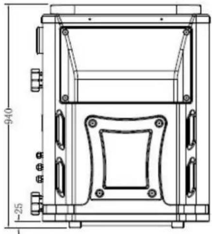
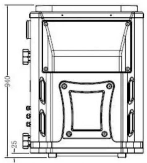
| Net dimensions | L/W/H | 1010*340*577mm | 1050*470*709mm | 910*707*940mm | ||||||
| Shipping dimensions | L/W/H | 1080*405*616mm | 1121*481*851mm | 935*790*975mm | ||||||
| Net/gross weight | Kg | 36/38 | 44/47 | 49/52 | 63/67 | 115/125 | 125/135 | 125/135 | 150/160 | 150/160 |
- Above data are subjects to modification without notice.
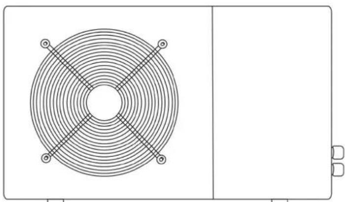
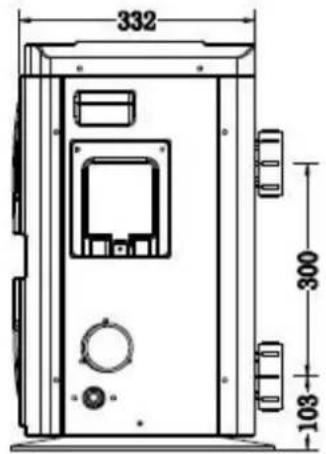
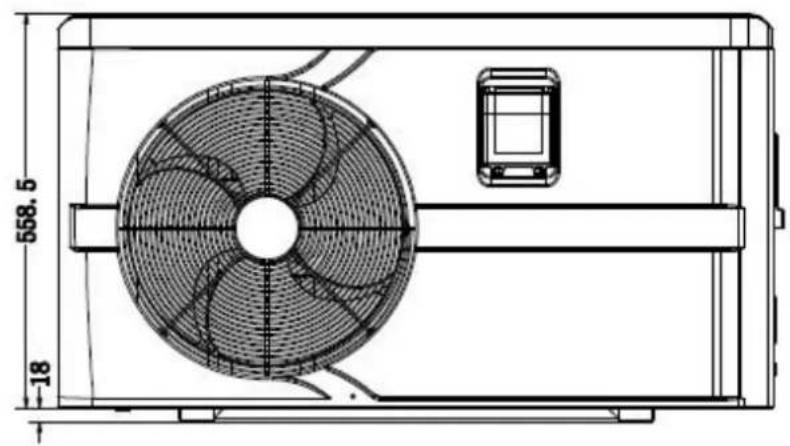
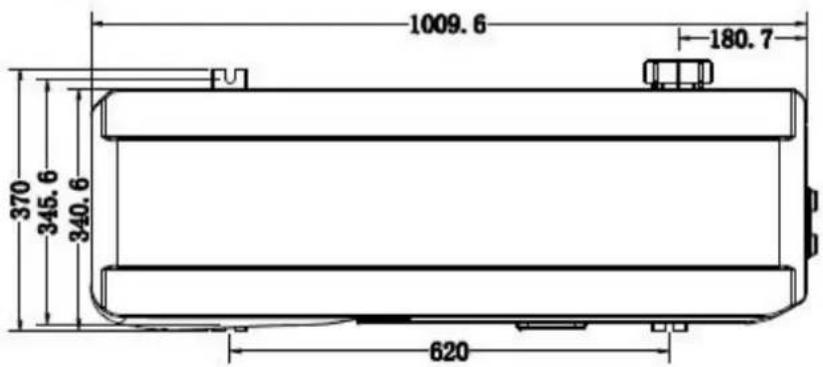
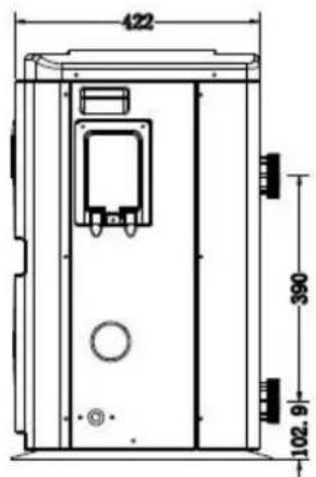
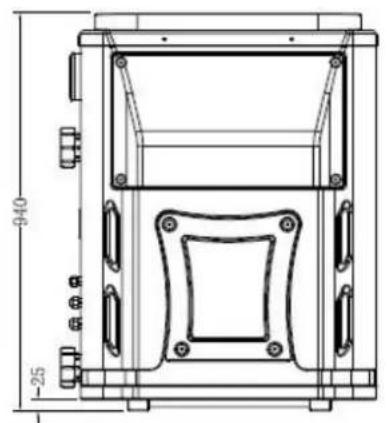
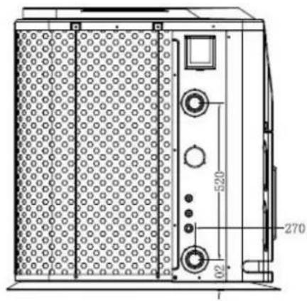
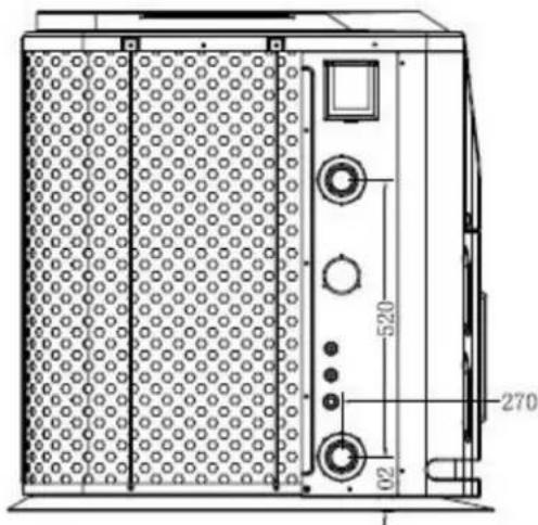
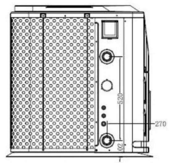
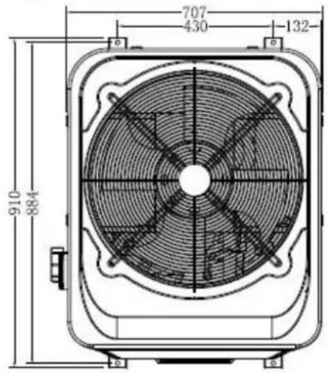
2. Dimension
Hydro Pro 5,7,10
Hydro Pro 13
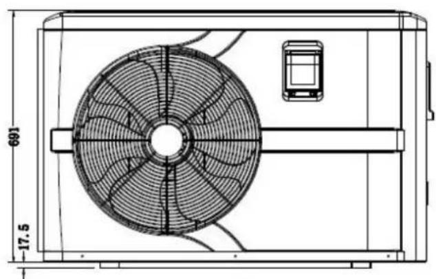
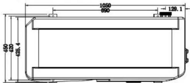
Hydro Pro 18, 22, 22T, 26, 26T

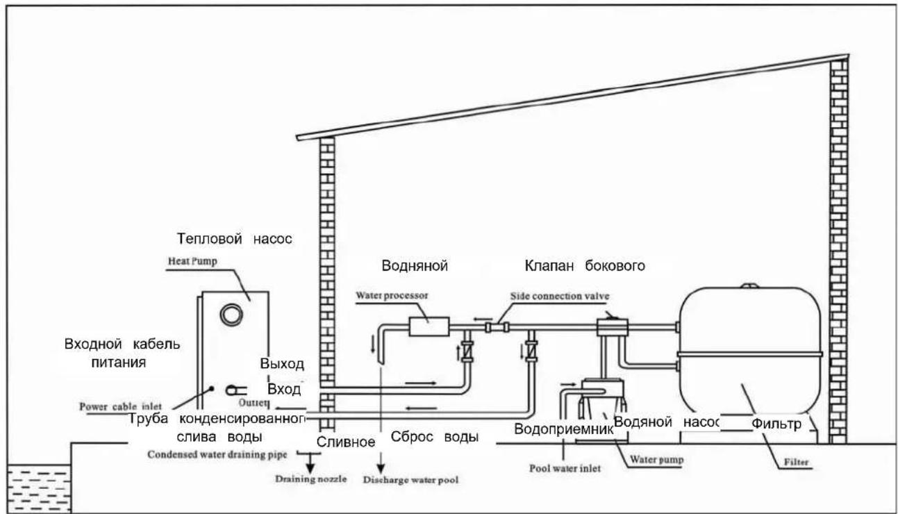
3. Installation and connection
3.1 Notes
The factory supplies only the heat pump. All other components, including a bypass if necessary, must be provided by the user or the installer.
Attention:
Please observe the following rules when installing the heat pump:
- Any addition of chemicals must take place in the piping located downstream from heat pump.
- Install a bypass if the water flow from the swimming pool pump is more than 20^ greater than the allowable flow through the heat exchanger of the heat pump.
- Install the heat pump above the water level of the swimming pool.
- Always place the heat pump on a solid foundation and use the included rubber m to avoid vibration and noise.
- Always hold the heat pump upright. If the unit has been held at an angle, wait a 24 hours before starting the heat pump.
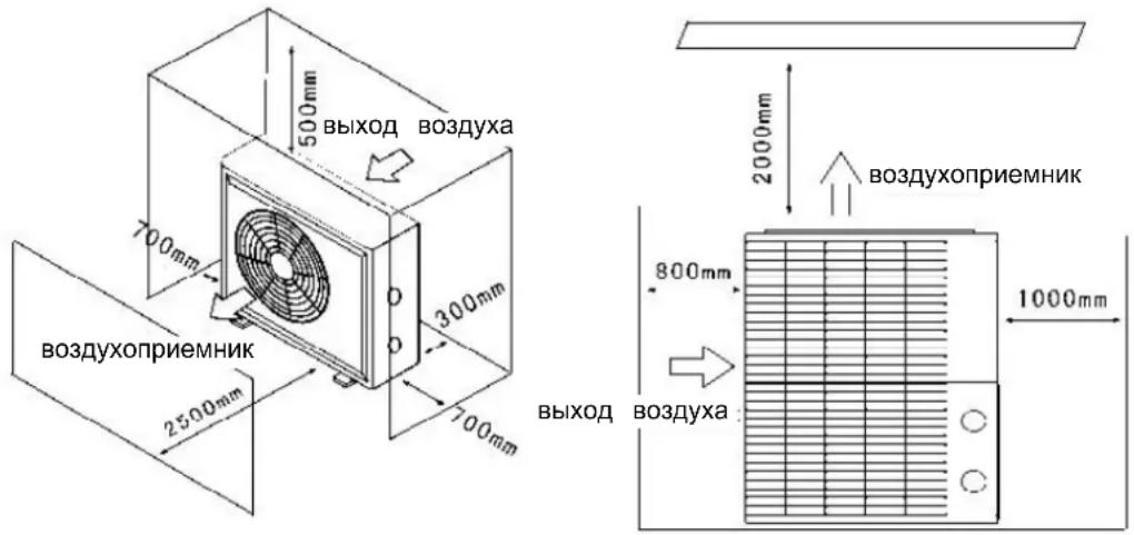
3.2 Heat pump location
The unit will work properly in any desired location as long as the following three items present:
1. Fresh air - 2. Electricity - 3. Swimming pool filters
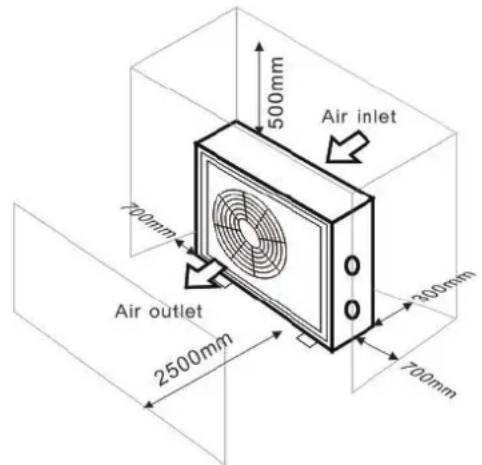
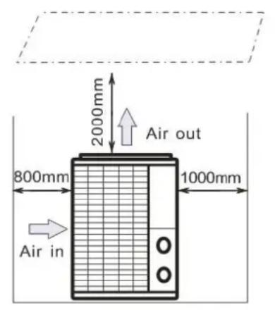
The unit may be installed in virtually any outdoor location as long as the specified mini distances to other objects are maintained (see drawing below). Please consult your installer for installation with an indoor pool. Installation in a windy location does not present any problem at all, unlike the situation with a gas heater (including pilot flame problems).
ATTENTION: Never install the unit in a closed room with a limited air volume in which expelled from the unit will be reused, or close to shrubbery that could block the air inlet locations impair the continuous supply of fresh air, resulting in reduced efficiency and possibly preventing sufficient heat output. See the drawing below for minimum dimensions.
3.3 Distance from your swimming pool
The heat pump is normally installed within a perimeter area extending 7.5m from the swimming pool. The greater the distance from the pool, the greater the heat loss in the As the pipes are mostly underground, the heat loss is low for distances up to 30m (1 and to the pump; 30m in total) unless the ground is wet or the groundwater level is rough estimate of the heat loss per 30m is 0.6kWh (2,000 BTU) for every 5^ difference between the water temperature in the pool and the temperature of the soil surrounding the pipe. This increases the operating time by 3% to 5% .
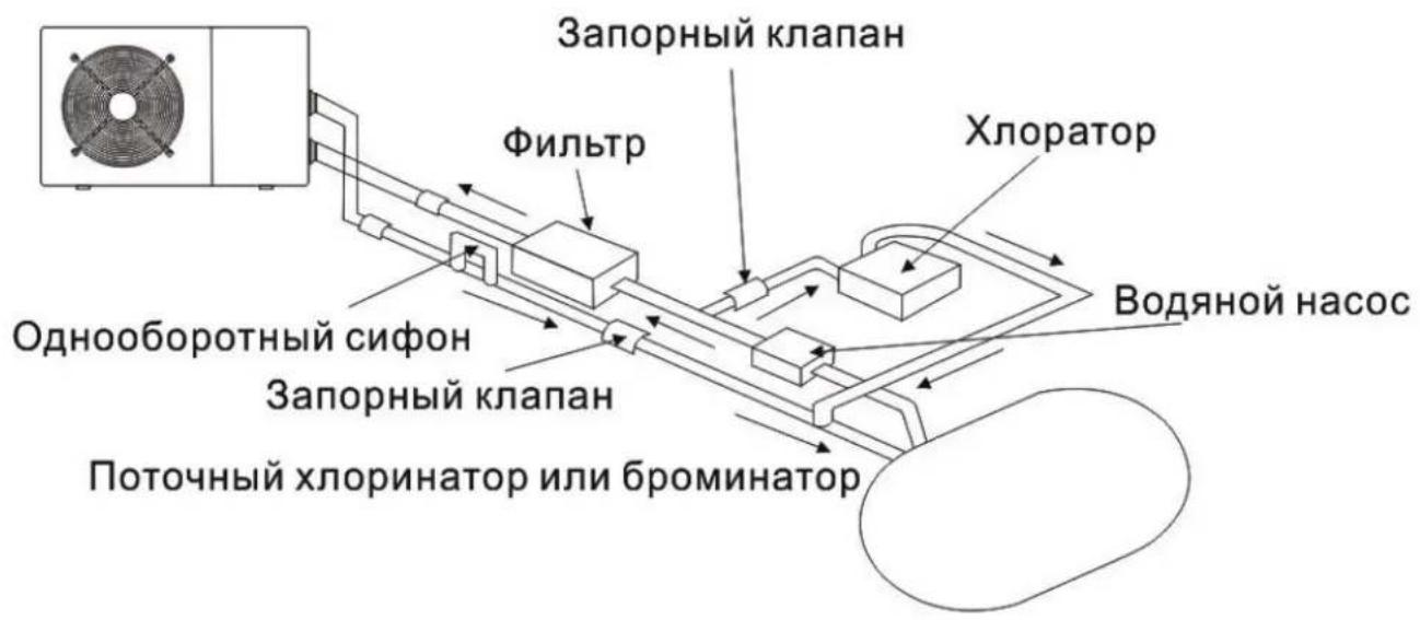
3.4 Check-valve installation
Note: If automatic dosing equipment for chlorine and acidity (pH) is used, it is essential to protect the heat pump against excessively high chemical concentrations which may corrode the heat exchanger. For this reason, equipment of this sort must always be fitted in the on the downstream side of the heat pump, and it is recommended to install a check-va to prevent reverse flow in the absence of water circulation.
Damage to the heat pump caused by failure to observe this instruction is not covered by warranty.
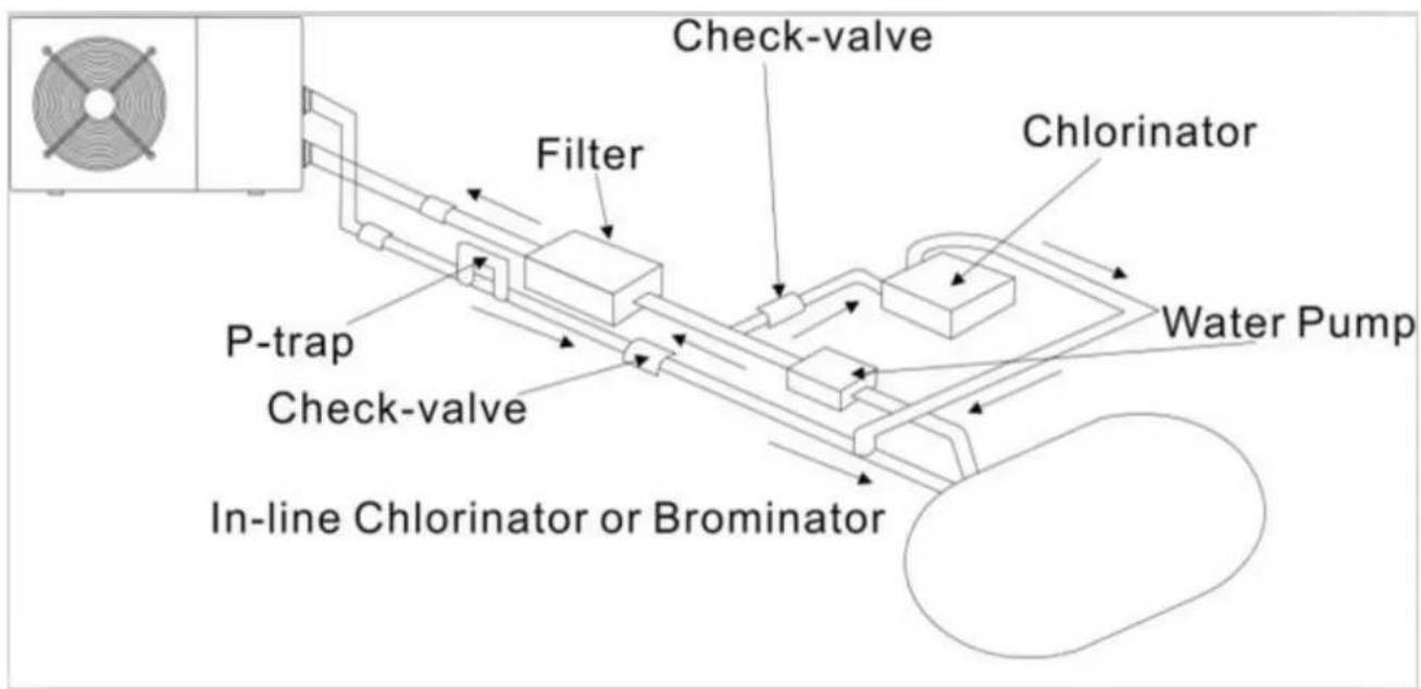
3.5 Typical arrangement
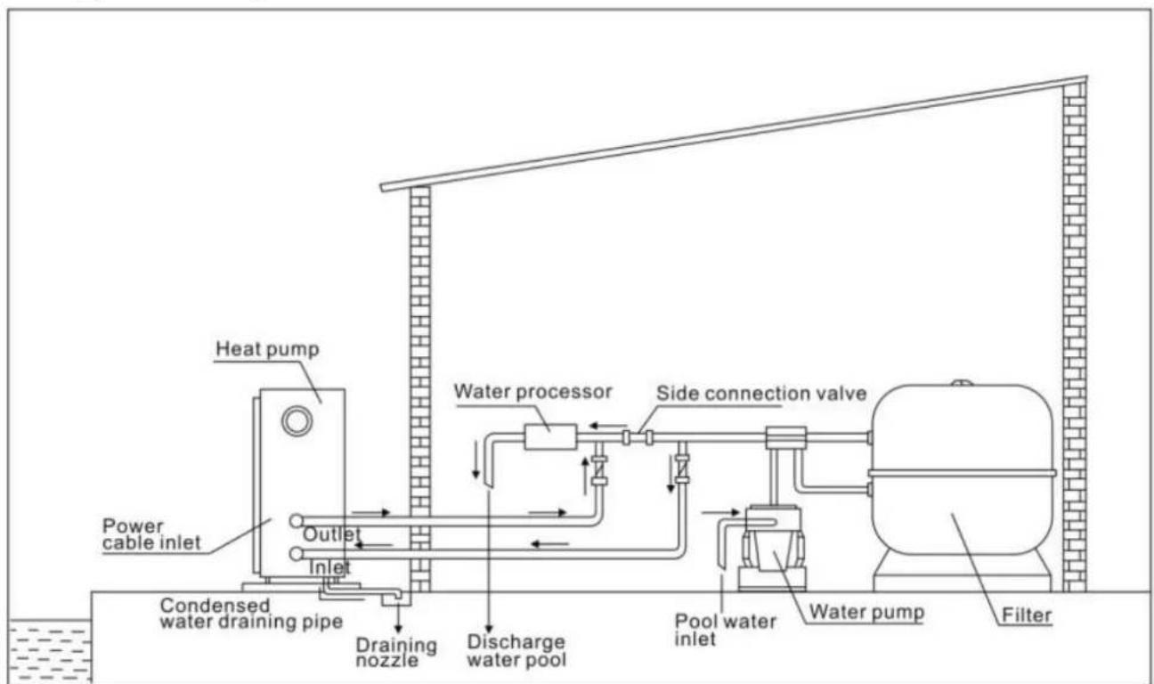
Note: This arrangement is only an illustrative example.
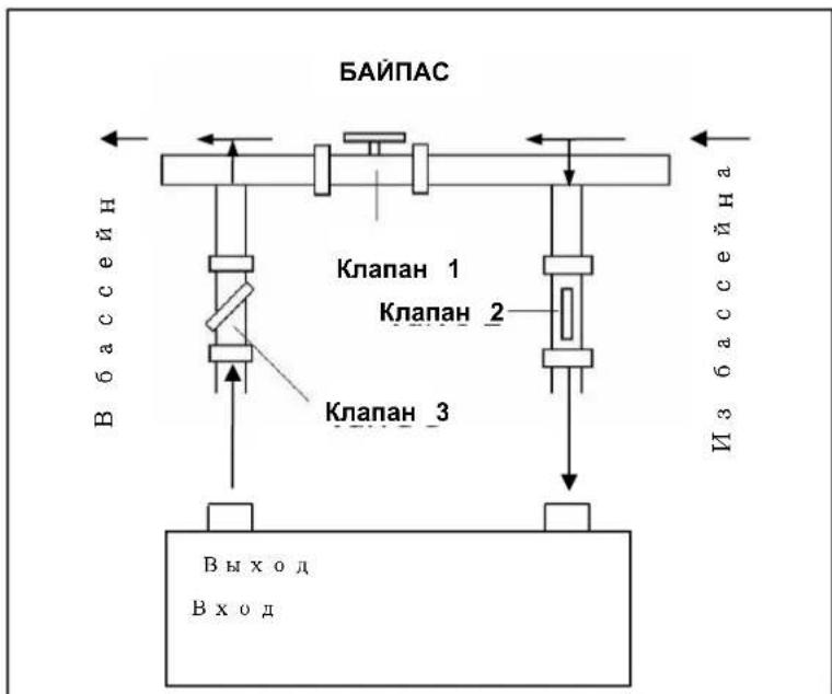
3.6 Adjusting the bypass
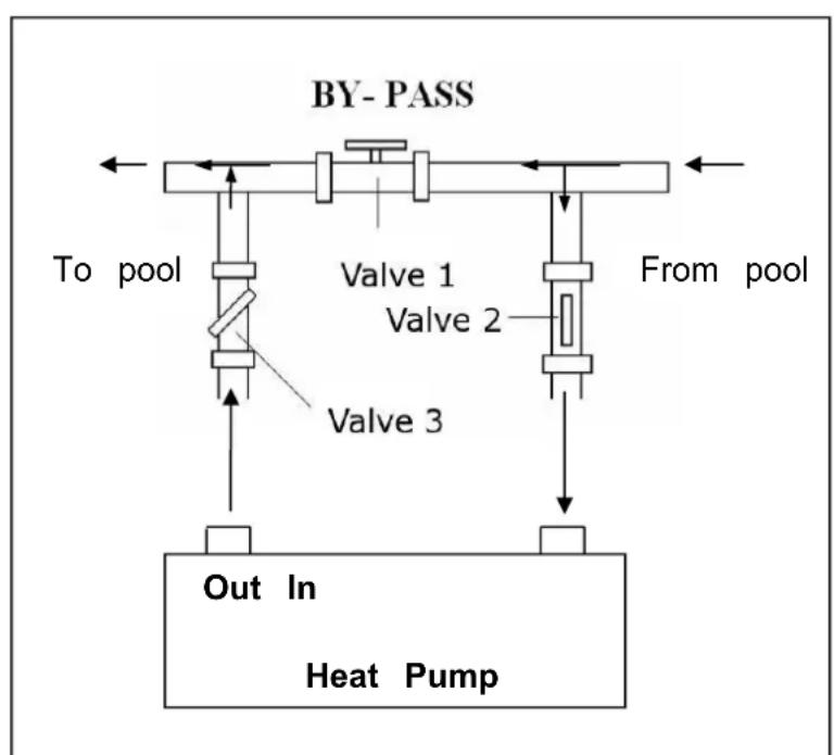
Use the following procedure to adjust bypass:
- fully open all three valves
slowly close valve 1 until the water pressure is increased by approximately 100 to 200 g - Close valve 3 approximately half-way to adjust the gas pressure in the cooling system
- If the display shows "ON" or error code EE3, close step by step the valve 2 increase water flow and stop when the code disappear.
Optimal operation of the heat pump occurs when the cooling gas presurbanis 22
This pressure can be read on the pressure gauge next to the control heat pump panel. These conditions the water flow through the unit is also optimal.
Note: Operation without a bypass or with improper bypass adjustment may result in sub-optimal heat pump operation and possibly damage to the heat pump, which renders the warranty null and void.
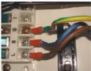
3.7 Electrical connection
Note: Although the heat pump is electrically isolated from the rest of the swimming pool system, this only prevents the flow of electrical current to or from the water pool. Earthing is still required for protection against short-circuits inside the unit.
Always provide a good earth connection.
Before connecting the unit, verify that the supply voltage matches the operating voltage of heat pump.
It is recommended to connect the heat pump to a circuit with its own fuse or circuit by (slow type; curve D) and to use adequate wiring (see table below).
For horizontal models (Hydro Pro 5, 7, 10 and 13): remove the top panel.
For vertical models (Hydro-Pro 18, 22, 22T and 26T): remove front panel.
Connect the electrical wires to the terminal block marked ‘ POWER SUPPLY ’ .
A second terminal block marked 'WATER PUMP' is located next to the first one. The pump (max. 5 A / 240 V) can be connected to the second terminal block here. This a filter pump operation to be controlled by the heat pump.
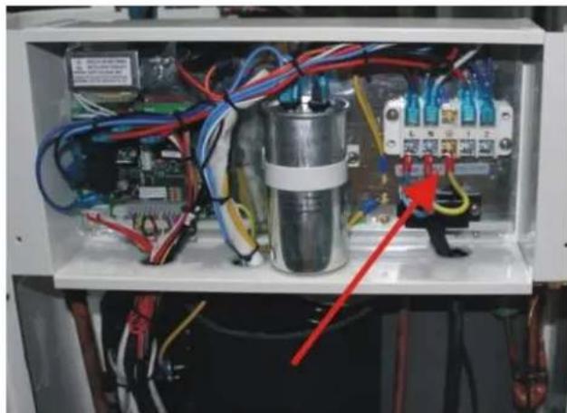
Note: In the case of three-phase models, swapping two phases may cause the electric r to run in the reverse direction, which can lead to damage. For this reason, the unit has built-in protective device that breaks the circuit if the connection is not correct. If the red above this safety device lights up, you must swap the connections of two of the ph wires.
| Model | Voltage (V) | Fuse or circuit breaker (A) | Rated current (A) | Wire diameter mm(with max. 15 m length) |
| HYDRO PRO5 | 220-240 | 15 | 4.1 | 2x 1.5 + 1.5 |
| HYDRO PRO7 | 220-240 | 15 | 4.7 | 2x 1.5 + 1.5 |
| HYDRO PRO10 | 220-240 | 20 | 7 | 2x 2.5 + 2.5 |
| HYDRO PRO13 | 220-240 | 25 | 9.1 | 2x 2.5 + 2.5 |
| HYDRO PRO18 | 220-240 | 40 | 13.4 | 2x 6 + 6 |
| HYDRO PRO22 | 220-240 | 45 | 15 | 2x 6 + 6 |
| HYDRO PRO22T | 3x 380 | 20 | 6.6 | 4x 2.5 + 2.5 |
| HYDRO PRO26 | 220-240 | 50 | 17.4 | 2x 6 + 6 |
| HYDRO PRO26T | 3x 380 | 25 | 7.7 | 4x 2.5 + 2.5 |
3.8 Initial operation
Note: In order to heat the water in the pool (or hot tub), the filter pump must be to cause the water to circulate through the heat pump. The heat pump will not start if the water is not circulating.
After all connections have been made and checked, carry out the following procedure:
-
Switch on the filter pump. Check for leaks and verify that water is flowing from and swimming pool.
-
Connect power to the heat pump and press the On/Off button on the electronic control panel. The unit will start up after the time delay expires (see below).
-
After a few minutes, check whether the air blowing out of the unit is cooler.
-
When turn off the filter pump, the unit should also turn off automatically, if not, the flow switch.
-
Allow the heat pump and the filter pump to run 24 hours a day until the desired water temperature is reached. The heat pump will stop running at this point. After this, it will restart automatically (as long as the filter pump is running) whenever the swimming pool water temperature drops 2 degree below the set temperature.
Depending on the initial temperature of the water in the swimming pool and the air temperature, it may take several days to heat the water to the desired temperature. A g swimming pool cover can dramatically reduce the required length of time.
Water Flow Switch:
It is equipped with a flow switch for protecting the HP unit running with adequate water rate. It will turn on when the pool pump runs and shut it off when the pump shuts off. Ool water level higher than 1 m above or below the heat pump's automatic adjustment I b, your dealer may need to adjust its initial startup.
Time delay - The heat pump has a built-in 3-minute start-up delay to protect the circuit from avoid excessive contact wear. The unit will restart automatically after this time delay expires. Even a brief power interruption will trigger this time delay and prevent the unit from resting immediately. Additional power interruptions during this delay period do not affect the 3-minute duration of the delay.
3.9 Condensation
The air drawn into the heat pump is strongly cooled by the operation of the heat pump heating the pool water, which may cause condensation on the fins of the evaporator. The amount of condensation may be as much as several litres per hour at high relative hum This is sometimes mistakenly regarded as a water leak.
4. Accessories
4.1 Accessories list
| Anti-vibration base, 4 pcs | Draining jet, 2 pcs | Waterproof box, 1 pc |
| 10M Signal wire, 1 pc | Water drainage pipes, 2 |
4.2 Accessories Installation
| Anti-vibration bases 1. Take out 4 Anti-vibration base 2. Put them one by one on the bottom of machine like the picture | |
| Draining jet 1. Install the draining jet under top bottom panel 2. Connect with a water pipe to out the water. Note: Lift the heat pump to insta jet. Never overturn the heat pum could damage the compressor. |
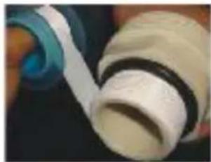
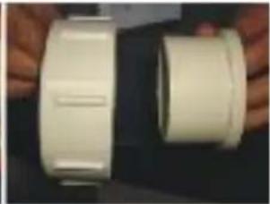
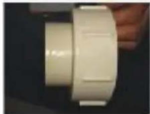

Water Inlet & outlet junction
- Use the pipe tape to connect water Inlet & outlet junction onto heat pump
- Install the two joints like the picture shows
- Screw them onto the water inlet outlet junction
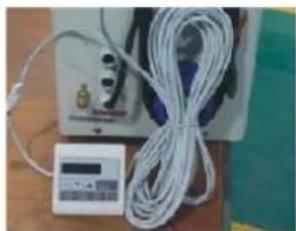
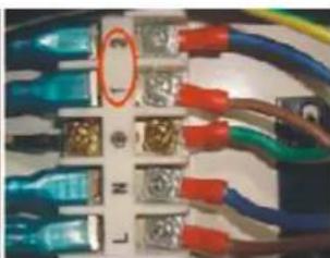
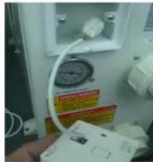
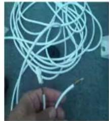
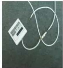
10M Signal wiring
- Take one side of the 10M S wire, to connect with the control
- The other side needs to be through the hole, like the third picture shows.
- Then connect to the PC board inside the machine : the brown - first joint; the blue one - - second joint; the yellow one - - third join
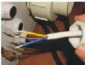
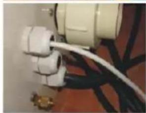
Cable wiring
- Connect the power supply wire through the white hole like the picture shows.
- Fix the other side on joints in the electric box.
Water pump wiring
- Connect the water pump wire through the white hole marked
- Fix the other side on joints i the electric box.
5. Electrical Wiring
5.1 SWIMMING POOL HEAT PUMP WIRING DIADRA
Hydro Pro 5/7/10
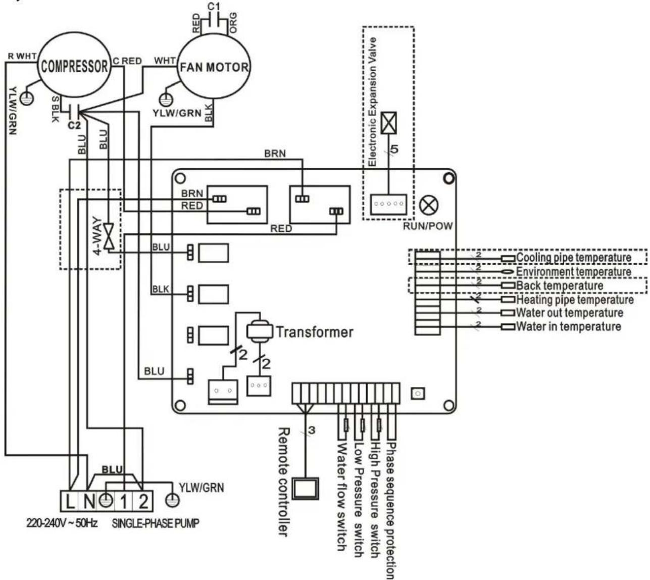
5.2 SWIMMING POOL HEAT PUMP WIRING DIADRA
Hydro Pro 13
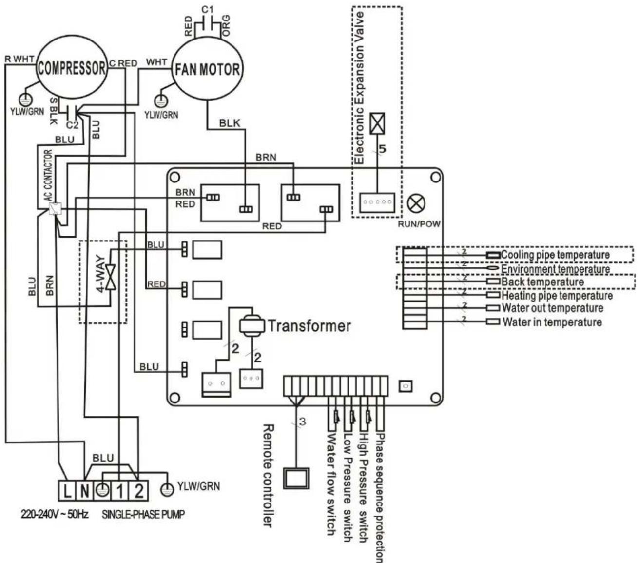
5.3 SWIMMING POOL HEAT PUMP WIRING DIADRA
Hydro Pro 18/22
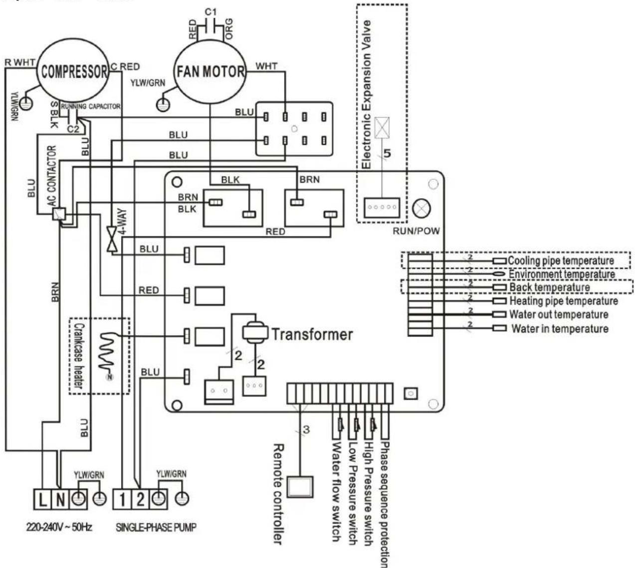
5.4 SWIMMING POOL HEAT PUMP WIRING DIADRA
Hydro Pro 26
5.5 SWIMMING POOL HEAT PUMP WIRING DIADRA
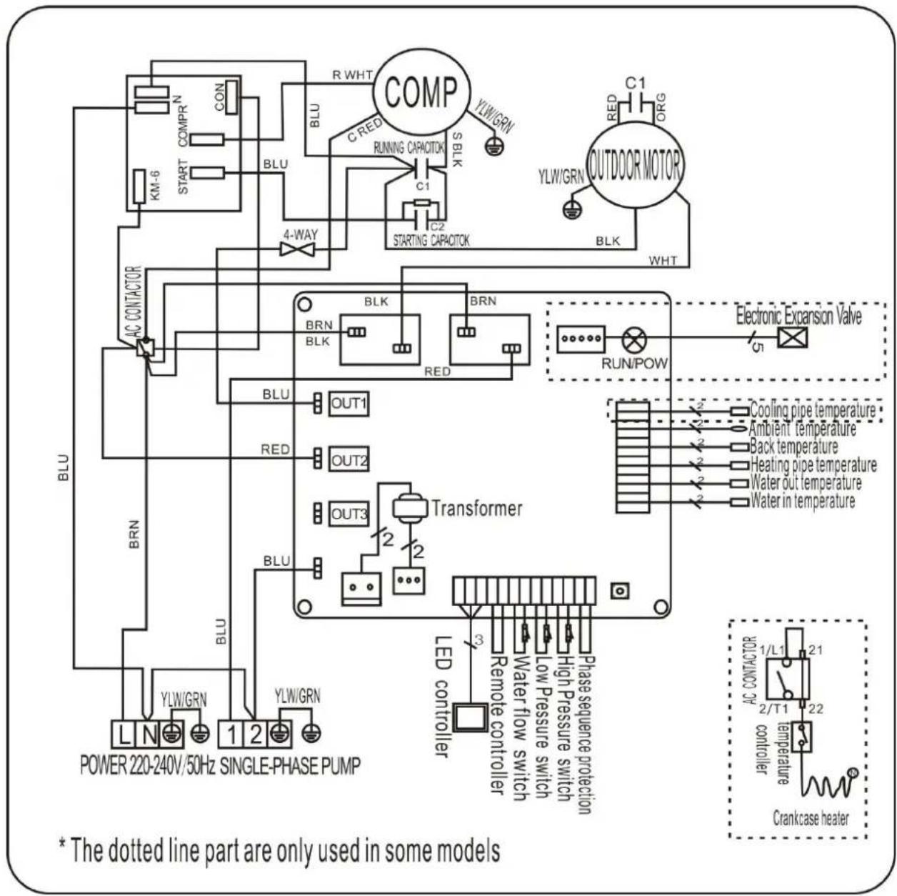
Hydro Pro 22T/26T
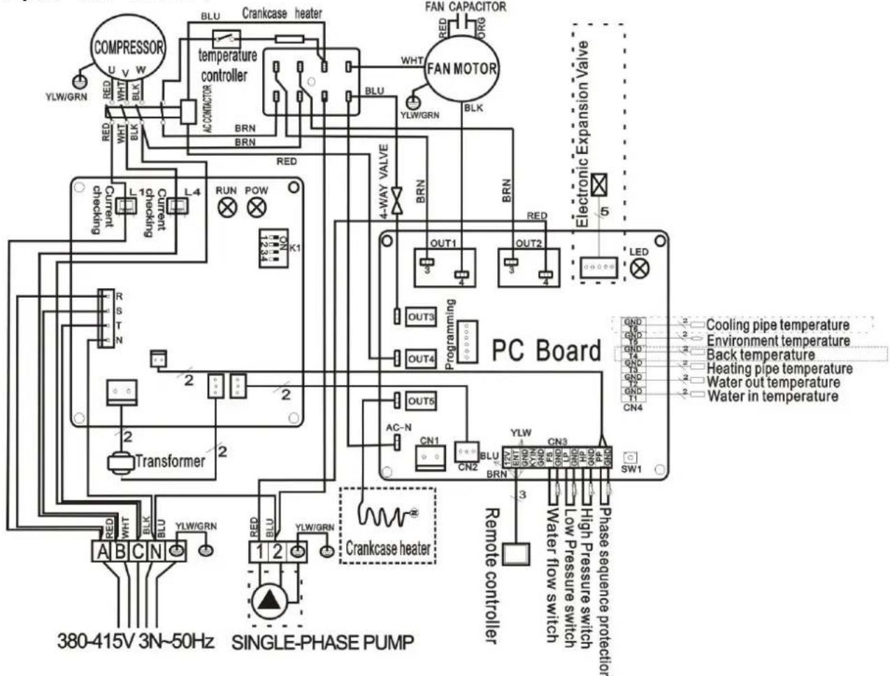
- The dotted line part are only used in some models
NOTE:
(1) Above electrical wiring diagram only for your reference, please subject machine posted wiring diagram.
(2) The swimming pool heat pump must be connected ground wire well, although the unit exchanger is electrically isolated from the rest of the unit. Grounding the unit is still required to protect you against short circuits inside the unit. Bonding is also required.
Disconnect: A disconnect means (circuit breaker, fused or un-fused switch) should be located within sight of and readily accessible from the unit. This is common practice on commercial and residential heat pumps. It prevents remotely-energizing unattended equipment and permits turning off power at the unit while the unit is being serviced.
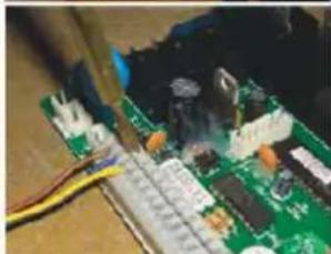
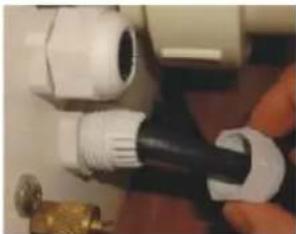
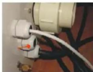
5.6 Installation of the display deportee
Photo (1) Photo (2) Photo (3)
- Disassembling of and degrafage control board of the connector (photo1)
- Installation of the provided cable (photo 2)
- To pass the cable by the press pack (photo 3) and to connect the sons directly
6. Display Controller Operation
6.1 The buttons of LED wire controller
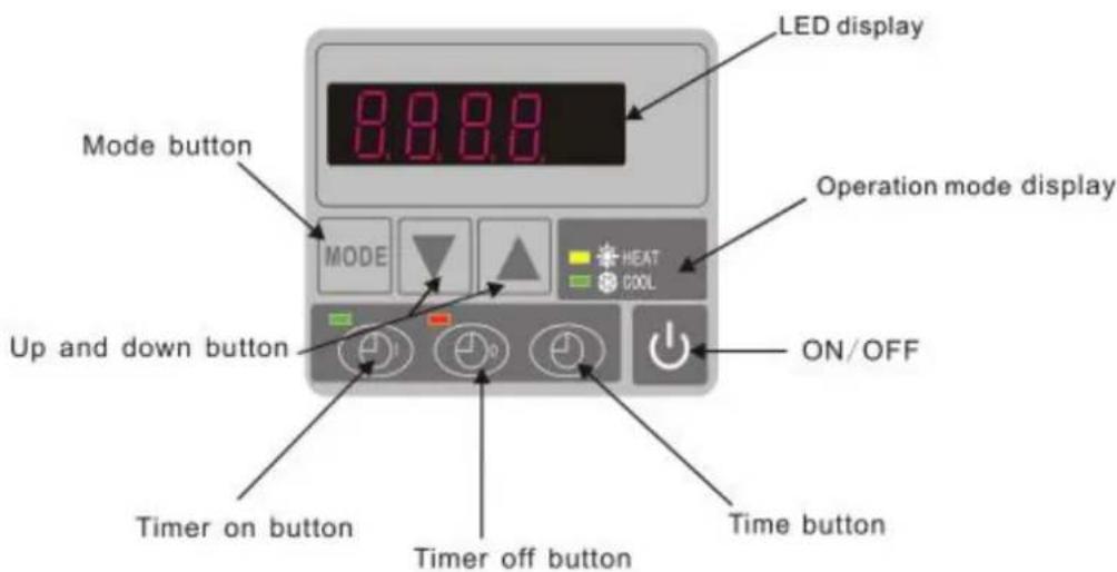
When the heat pump is running, the LED display shows the inlet water temperature.
When the heat pump is standby, the LED display shows the real time.
6.2 Start or stop the heat pump.
Press to start the heat pump unit, the LED display shows the desired water temperature for 5 seconds, then shows the inlet water temperature.
Press to stop the heat pump unit.
6.3 Choose heating or cooling mode:
Press until "heat" or "Cool" light is on.
6.4 Setting the real time
On standby or running mode, press, then press or to adjust hour/minute.
Then press the again to store the new data.
When setting the time, and cannot work.
6.5 Water temperature setting:
On standby or running mode, press and to adjust the desired water temperature
Note : the heat pump can running only if the water circle/filtration system is
6.6 Automatic start/stop the heat pump
To set the time to start the unit
Press to set the time to start the unit, then press or to adjust the time (set the time for start
5 minutes after the water pump).
Press again to store the new data.
To set the time to stop the unit
Press to set the time to stop running, then press or to adjust the time (set the time for stop
5 minutes before the water pump).
Press again to store the new data.
6.7 Concell the automatic start/stop To conceal the automatic starter
Press, then press, light off and the automatic start is off. To conceal the automatic starter
Press, then press, light off and the automatic stop is off.
Note : If the water filtration system is stop before the heat pump, the unit wi (security condition) and the code EE3 or ON advertise on the controller. It is important to program the heat pump link the time program of the water system. For restart the heat pump, turn off and turn on the electrical power supply to unit.
7. Running data setting
7.1 How to check the parameters
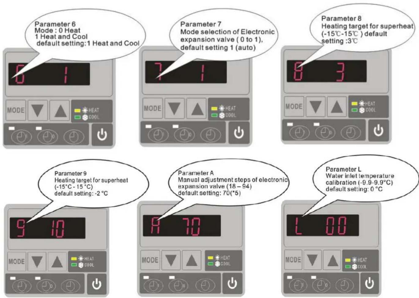
On standby or running mode, long press for 10 seconds, then press or to check the parameters (from 0 to H, see operation parameter table).
7.2 How to adjust the parameters (Can only adjust on standby mode)
1) Long press for 10 seconds, press again to select the data (from 0 to L, see operation parameter table) you want to adjust.
2) Then press or to adjust the parameter, press again to store the new data.
3) Then press or select the other datas you want to adjust, repeat above operation.
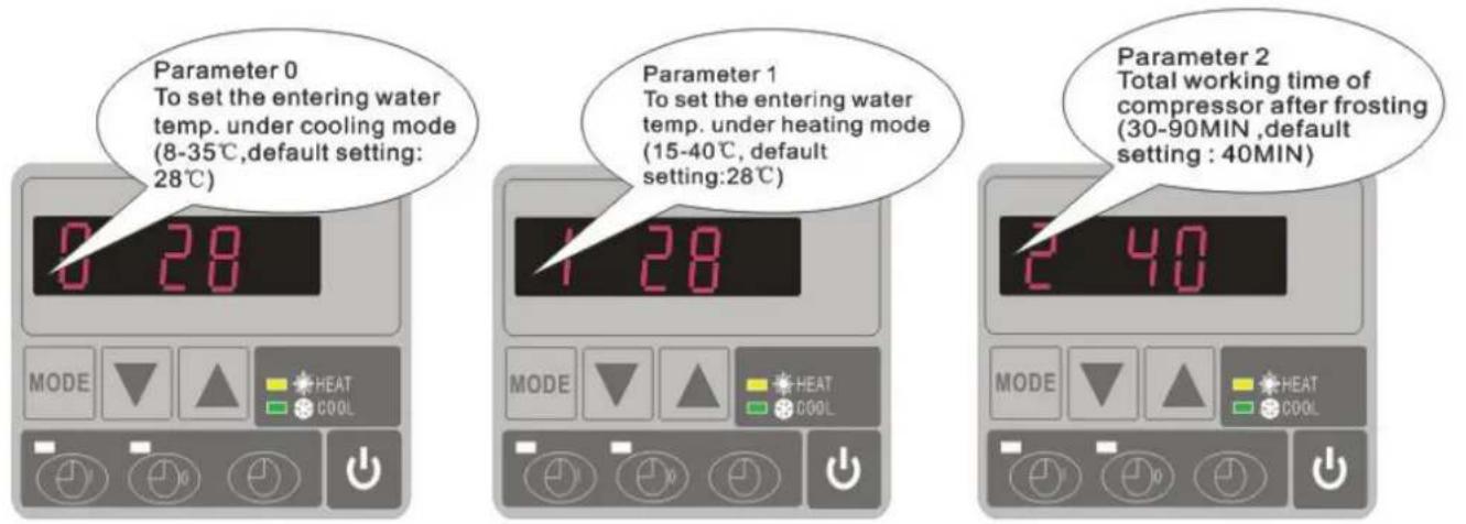
Please kindly noted:
A) Press "MODE" to choose mode (Mode only be changed for "1" or "2" setting of para 6)
B) Mode can be changed while running
C) Auxiliary electrical heating is not applicable to these modes.
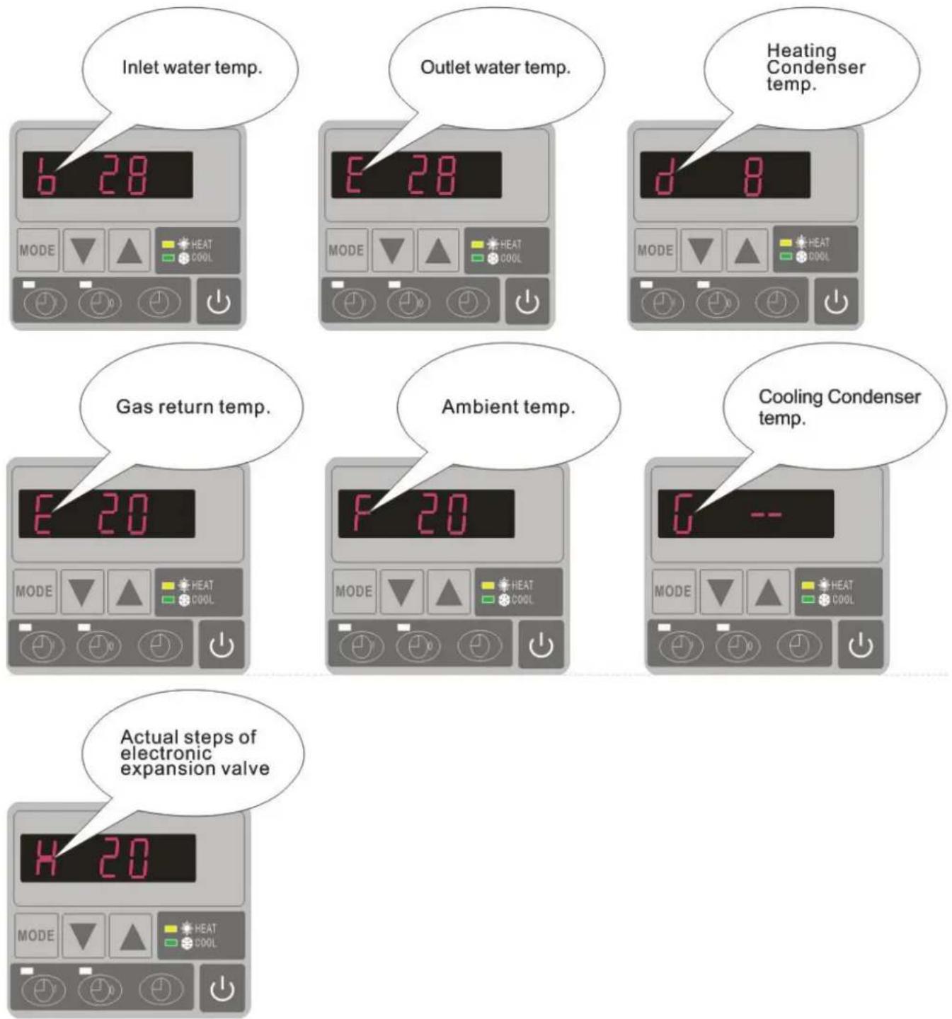
7.3 How to know the current status
| Parameter | Meaning | Range | Default | Remarks |
| 0 | To set the entering water tem under cooling mode | 8-35°C | 28°C | Adjustable |
| 1 | To set the entering water tem under heating mode | 15-40°C | 28°C | Adjustable |
| 2 | Entry into defrosting time perio | 30-90MIN | 40MIN | Adjustable |
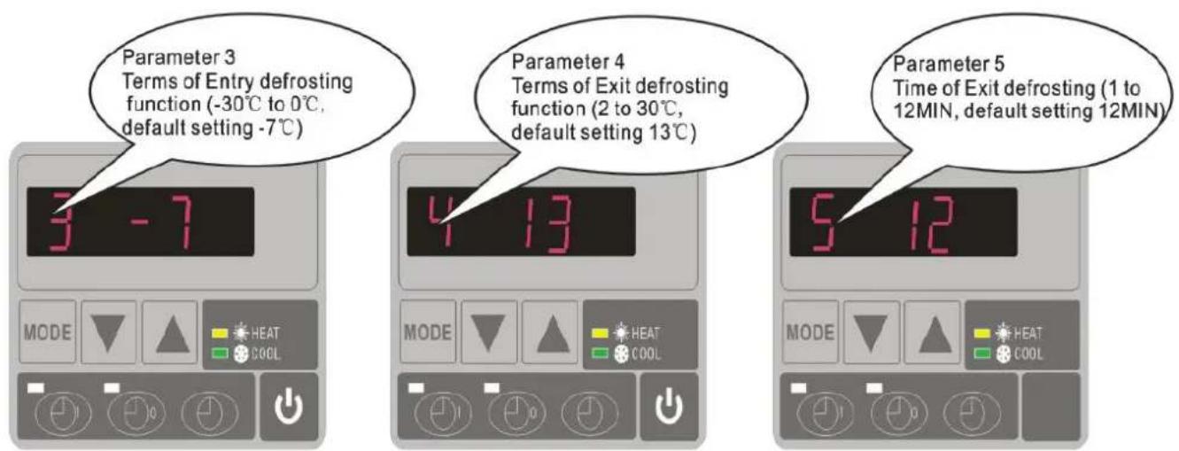
| 3 | Terms of Entry defrosting funct | -30°C to 0°C | -7°C | Adjustable |
| 4 | Terms of Exit defrosting | 2 to 30°C | 20°C | Adjustable |
| 5 | Time of Exit defrosting | 1 to 12MIN | 12MIN | Adjustable |
| 6 | Mode: 0 Heat 1 Heat and Co | 0-1 | 1(Heat and Cool) | Adjustable |
| 7 | Mode selection of Electronic expansion valve | 0-1 | 1(xto) | Adjustable |
| 8 | Superheat for heating target | -15°C-15°C | 3°C | Adjustable |
| 9 | Superheat for cooling target | -15°C-15°C | -2 °C | Adjustable |
| A | Manual adjustment steps of electronic expansion valve | 18-94 | 70 | Adjustable |
| B | Inlet water temperature | -9-99°C | Exact testing by value | |
| C | Outlet water temperature | -9-99°C | Exact testing by value | |
| D | Condenser temperature under heating mode | -9-99°C | Exact testing by value | |
| E | Gas return temperature | -9-99°C | Exact testing by value | |
| F | Ambient temperature | -9-99°C | Exact testing by value | |
| G | Condenser temperature under Cooling mode | -9-99°C | Exact testing by value | |
| H | Actual steps of electronic expansion valve | N*5 | Exact testing by value | |
| L | Entering water temperature calibration | -9.9-9.9°C | 0°C | Adjustable |
Remarks:
(1) When HP stop running in 30 seconds, water pump will shut off automatically
(2) LED wire controller can operate the water pump after connected additional cable to the pump device in the position of "PUMP" terminal accurately.
(3) It is necessary to put an extra 3-phase transfer device for 3 phase water pump.
8. Troubleshooting
8.1 Error code display on LED wire controller
| Malfunction | Error code | Reason | Solution |
| Inlet water temperature sensor failure | PP1 | The sensor in open or short circuit | Check or change the sensor |
| Outlet water temperature sensor failure | PP2 | The sensor in open or short circuit | Check or change the sensor |
| Heating condenser sensor failure | PP3 | The sensor in open or short circuit | Check or change the sensor |
| Gas return sensor failure | PP4 | Connect some wire wrongly c gas return sensor position | Confirm there is nothing on point, restart the machine |
| Ambient temperature sensor failure | PP5 | The sensor in open or short circuit | Check or change the sensor |
| Temperature difference between water inlet and outlet is too much | PP6 | Water flow volume not enough ,water pressure difference is too low | Check the water flow volume water jammed or not |
| Cooling outlet water temperature is too low | PP7 | Water flow volume is not enough | Check the water flow or water system is jammed or not |
| First grade antifreeze protection in Winter | PP7 | Ambient temperature or water inlet temperature is too low | Water pump will run automatically for first grade antifreeze |
| Second grade antifreeze protection in Winter | PP7 | Ambient temperature or water inlet temperature is too low | Heat pump will start heating second grade antifreeze |
| Cooling condenser sensor failure | PP8 | Connect some wire wrongly c gas return sensor position | Confirm there is nothing on point, restart the machine |
| High pressure protection | EE1 | 1. Refrigerant is too much2. Air flow is not enough | 1. Discharge redundant refrigerant from HP gas system2. Clean the air exchanger |
| Low pressure protection | EE2 | 1. Refrigerant is not enough2. Water flow is not enough3. Filter jammed or capillary jammed | 1. Check if there is any gas leakage ,re-fill the refrigerant2. Clean the air exchanger3. Replace the filter or capillary |
| Flow switch closed | EE3 or "ON" | Low water flow, wrong flow direction, or flow switch failure | Check if the water flow is enough and flow in right direction, or else the flow switch could be failed. |
| Power supply connections wrong (for phase unit) | EE4 | Wrong connection or lack of connection | Check the connection of power cable |
| Inlet and outlet water temperature difference malfunction | EE5 | Water flow volume is not enough ,water pressure difference is too low | Check the water flow rate ,of water system is jammed or |
| Communication failure | EE8 | Wire connection is not good | Check the wire connection |
8.2 Other Malfunctions and Solutions (No display on LED wire controller)
| Malfunctions | Observing | Reasons | Solution |
| Heat pump is not running | LED wire controller no display. | No power supply | Check cable and circuit breaker if it is connect |
| LED wire controller displays the actual time. | Heat pump under standby status | Startup heat pump to r | |
| LED wire controller displays the actual water temperature. | 1. Water temperature is reaching to setting value, HP under constant temperature status. 2. Heat pump just starts to run. 3. Under defrosting. | 1. Verify water temperature setting. 2. Startup heat pump after a few minutes. 3. LED wire controller should display "Defrosting". | |
| Water temperature is cooling when HP run under heating mode | LED wire controller displays actual water temperature and no error code displays. | 1. Choose the wrong mode. 2. Figures show defects. 3. Controller defect. | 1. Adjust the mode to proper running 2. Replace the defect LED wire controller, and then check the status after changing the running mode, verifying the water inlet and out temperature. 3. Replace or repair the heat pump unit |
| Short running | LED displays actual water temperature, no error code displays. | 1. Fan NO running. 2. Air ventilation is not enough. 3. Refrigerant is not enough. | 1. Check the cable connections between the motor and fan, if necessary, it should be replaced. 2. Check the location of heat pump unit, and eliminate all obstacles to make good air ventilation. 3. Replace or repair the heat pump unit. |
| water stains | Water stains on heat pu unit. | 1. Concreting. 2. Water leakage. | 1. No action. 2. Check the titanium heat exchanger carefully if it is any defect. |
| Too much ice on evaporator | Too much ice on evaporator. | 1. Check the location of heat pump unit, and eliminate all obstacles to make good air ventilation. 2. Replace or repair the heat pump unit. |
9. Exploded Diagram and Maintenance
9.1 Exploded Diagram
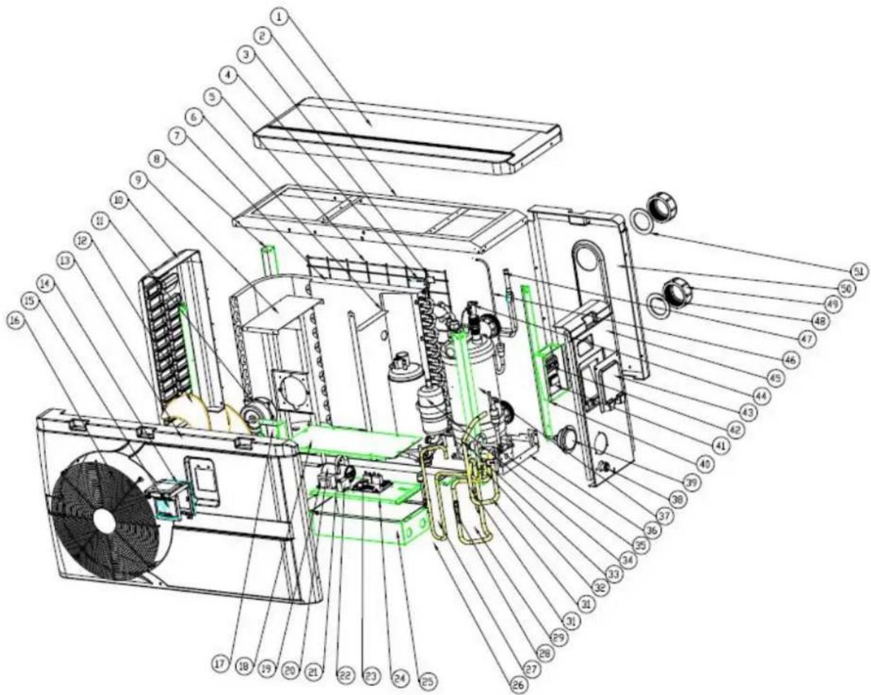
Model 7 kw
| NO | Part Name | NO | Part Name |
| 1 | Top cover | 27 | Exhaust pipe |
| 2 | Top frame | 28 | Needle |
| 3 | Ambient temp. sensor | 29 | Return pipe |
| 4 | Ambient temp. sensor clip | 30 | Low pressure switch |
| 5 | Back grill | 31 | Piping (4-way valve to exchanger) |
| 6 | Isolation panel | 32 | Piping (4-way valve to collective pipe) |
| 7 | Evaporator | 33 | 4-way valve |
| 8 | Pillar | 34 | Compressor |
| 9 | Motor fixture | 35 | Base tray |
| 10 | Left panel | 36 | Piping (exchanger to capillary) |
| 11 | Motor | 37 | Heat exchanger |
| 12 | Fan blade | 38 | Drainage plug |
| 13 | Front panel | 39 | Gauge |
| 14 | Waterproof box | 40 | Terminal box |
| 15 | Display | 41 | Clip |
| 16 | Ventilation | 42 | 5-seat terminal |
| 17 | Wiring box | 43 | Terminal cover |
| 18 | Electric box cover | 44 | Water flow switch |
| 19 | Transformer | 45 | Right panel |
| 20 | Compressor capacitor | 46 | Distribution pipe |
| 21 | Clip | 47 | Collective pipe |
| 22 | Motor capacitor | 48 | Blue rubber ring |
| 23 | PCB | 49 | Water connection |
| 24 | scaleboard | 50 | Back panel |
| 25 | Electric box | 51 | Red rubber ring |
| 26 | High pressure switch |
Model 22kw
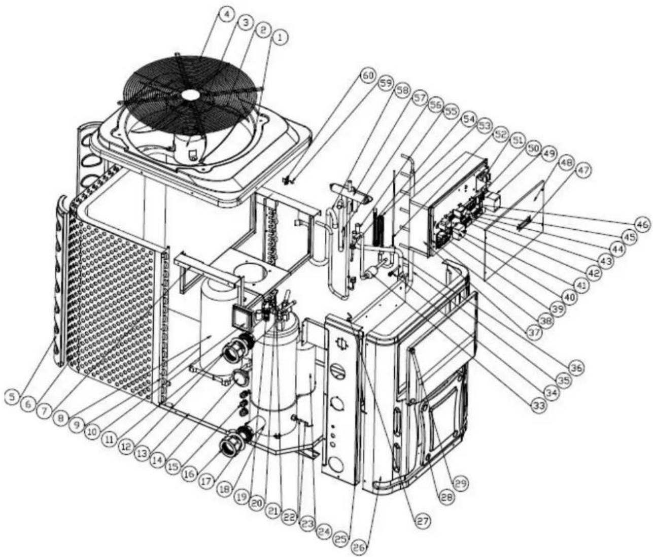
| NO | Part Name | NO | Part Name |
| 1 | Top cover | 31 | Exhaust pipe |
| 2 | Fan blade | 32 | High pressure switch |
| 3 | Motor | 33 | Filter sembly |
| 4 | Top grill | 34 | Needle |
| 5 | Back pillar | 35 | Collective pipe |
| 6 | / | 36 | 4-way valve to collective pipe |
| 7 | Motor fixture | 37 | Electric box |
| 8 | Compressor | 38 | Scaleboard |
| 9 | Evaporator | 39 | PCB |
| 10 | Controller | 40 | Transformer |
| 11 | Water connection | 41 | Motor capacitor |
| 12 | rubber ring | 42 | Terminal |
| 13 | Base tray | 43 | Temp. controller fixture |
| 14 | Gauge | 44 | Temp. controller |
| 15 | Waterproof connection | 45 | Clip |
| 16 | Water connection | 46 | Terminal |
| 17 | rubber ring | 47 | Wire cover |
| 18 | Heat exchanger | 48 | Electric box cover |
| 19 | Water flow switch | 49 | AC contactor |
| 20 | Outlet water temp. sensor clip | 50 | Water pump terminal |
| 21 | Outlet water temp. sensor | 51 | Phase protection board |
| 22 | Inlet water temp. sensor clip | 52 | Distributor assembly |
| 23 | Inlet water temp. sensor | 53 | Capillary assembly |
| 24 | Segregator | 54 | Low pressure switch |
| 25 | Left panel | 55 | 4-way valve to segregator |
| 26 | Front panel | 56 | 4-way valve to heat exchanger |
| 27 | Piping temp. sensor | 57 | 4-way valve |
| 28 | Service panel 2 | 58 | Return pipe |
| 29 | Service panel 1 | 59 | Ambient temp. sensor |
| 30 | Electric box support panel | 60 | Ambient temp. sensor clip |
10. Maintenance
(1) You should check the water supply system regularly to avoid the air entering the system and occurrence of low water flow, because it would reduce the performance and reliability of HP unit.
(2) Clean your pools and filtration system regularly to avoid the damage of the unit as of the dirty of clogged filter.
(3) You should discharge the water from bottom of water pump if HP unit will stop runn a long time (specially during the winter season).
(4) In another way, you should check the unit is water fully before the unit start to run
(5) After the unit is conditioned for the winter season, he is preconize to cover the heat with special winter heat pump.
(6) When the unit is running, there is all the time a little water discharge under the un
11. Warranty and returns
11.1 Warranty
LIMITED WARRANTY
Thank you for purchasing a heat pump from us.
This warranty covers manufacturing and material defects in all components for a period of two date of purchase.
This warranty is limited to the original purchaser in the retail sector. It is not transferable, and applicable to products that have been removed from their original installation location. The liabhi manufacturer is limited to the repair or replacement of defective components and does not incl labour for removing and replacing the defective component(s), the cost of transporting component to the factory, or costs associated with other materials necessary for carrying out repairs. This not cover any defects attributable to the following causes:
- Installation, operation or maintenance of the product other than in accordance with the guide and/or instructions in the Installation and Operation Manual supplied with the product.
- Faulty or deficient work performed on the product by an installer.
- Failure to maintain the correct chemical balance in the swimming pool [pH between 7.0 and 7.8; total alkalinity (TA) between 80 and 150 ppm; free chlorine concentration between 0.5 and total dissolved solids (TDS) less than 1,200 ppm; maximum salt concentration 8 g/l].
- Improper use, modification, accident, fire, flood, lighting strike, rodents, insects, negligence, nor or force majeure.
- Deposits, freezing, or other conditions that impair proper water flow through the product.
- Operating the product with a flow rate outside the published minimum and maximum specif
- Use of components or accessories not designed or made for this product.
- Chemical contamination of the air used by the product or improper use of decontaminating chemicals, such as the addition of decontaminating chemicals through the skimmer or in the pi located upstream of the heat pump and the cleaning hose.
- Overheating, improper electrical connections, improper power supply, secondary damage attribute to defective O-rings, diatomaceous filters or filter cartridges, or damage caused by putting the operation in the absence of sufficient water.
LIMITATIONS ON LIABILITY
This is the sole warranty provided by the manufacturer. Nobody is authorised to grant other v
THIS WARRANTY REPLACES ALL OTHER EXPLICITLY GRANTED OR IMPLICIT WARRANTIES, INCLUDING BUT NOT LIMITED TO ANY FORM OF IMPLICIT WARF OF SUITABILITY FOR A PARTICULAR PURPOSE OR FITNESS FOR SALE. WE EXPI SAVOW ANY LIABILITY FOR INDIRECT, INCIDENTAL OR CONSEQUENTIAL LOSS DAMAGE OF A PUNITIVE NATURE RESULTING FROM THE VIOLATION OF AN EXPLICITLY GRANTED OR IMPLICIT WARRANTY.
This warranty gives you specific legal rights, which may vary depending on the country.
WARRANTY CLAIMS
To ensure prompt handling of your warranty claim, please contact your dealer and provide the information to the dealer: proof of purchase, model number, serial number and date of installment installer will contact the factory to obtain instructions regarding the procedure for making warranty and to find out the location of the closest service centre.
All returned components must be marked with a RMA number so that it can be determined whether they are covered by the warranty.
11.2 RMA request form
| Company: | Date: | |||||
| Street address: | ||||||
| City/town: | Postal code: | Country: | ||||
| Contact: | Phone: | |||||
| E-mail: | Fax: | |||||
| Contact: | Date: |
| Reserved for internal use | |||
| RMA no.: | |||
| Assigned by: | Date: | ||
Reason for return: Copy of customer invoice included?

| RMA request accompanied by other documents? |
| Description of the documents: |
| Model no.: | Invoice no.: | ||
| Serial number | Invoice date: | ||
| Problem: | |||
Warranty repair policy
- Shipping costs for returned products must be paid in advance. All shipping costs associated with a return shipment are borne by you.
- Products may be sent back to us only after prior approval by the company. Return shipments for which approval has not been given by the company will be sent back, with all shipping costs to be borne by you.
- We will replace or repair the products and return them to you free of charge using the shipping service of your choice.
- If you choose express shipment (by a shipping service selected by you), you are responsible for paying the shipping costs.
Return procedure
- Before requesting an RMA number from us, please check whether you have properly observed the installation and use instructions in the manual.
- Contact our RMA department by phone and ask for an RMA request form.
- Ensure that all fields of the RMA request form are fully completed.
- In the case of returns during the warranty period, please include the customer copy of your original sales invoice.
-
Send the RMA request form, the sales invoice and any other relevant documents (photos, etc.) to us or provide them by e-mail. An RMA number will be assigned to you within 24 hours after we receive the necessary documents. We may refuse to assign you an RMA number if the information mentioned in points 3 and 4 above is missing.
-
The RMA number must be marked clearly on the shipping label of the package and noted on the shipping documents.
- All products received by us that lack labels or that have incorrect, incomplete or unreadable labels will be refused, with return shipping costs to be borne by you.
- All packages delivered to us with clearly visible damage will be refused immediately.
- Before returning products, please check that the products you intend to return to us are the same as the products for which an RMA number was issued. If the received products do not match the products registered under the assigned RMA number, we will return all of the products at your expense.
- No return shipments at all will be accepted without an RMA number. Absolutely no exceptions to this rule are allowed.
- An RMA number remains valid for just 21 calendar days after it is assigned. We reserve the right to refuse to accept products returned to us if they are received more than 21 days after the date when the RMA number was assigned. Products not covered or no longer covered by the warranty
The customer is responsible for paying shipping and repair costs. The estimated repair costs will be advised after problem(s) with the returned products have been diagnosed.
The minimum charge of a diagnosis is €50.00.
MegaGroup Trade Holding BV
Doornhoek 4205 - 5465 TG Veghel - The Netherlands
P.O. Box 430 - 5460 AK Veghel - The Netherlands
T: +31 413 747 300
www.megagrouptrade.com -info@megagrouptrade.com
MegaGroup Trade Holding BV
Modellen 18, 22, 26, 22T, 26T
3.4 Controle klep installation
6.3 Kies verwarming of koel mode:
MegaGroup Trade Holding BV
Modell 18, 22, 26, 22T, 26T
3ΦΦEKTINBHOCTN I, BO3MOXHO, INpeTCTByET DOCTaTOHOMY KOJNUeCTBy TEJIa.
CMOTpnte dnaarpammy Hnke o MUNHmAbhBix pacCToHHnx.
3.3 PacctoHne ot nlaBaTeIbHoro 6accSeHa
TennoBoH haooc oBlyHo yctaHaBnBaetc B npedeJax nepImeTp a TeppToPn, npocTpaUoche Ha 7,5 M ot 6accSeHa. Yem 6OJIbWe paCtOraHne OT 6accEHa, Tem 6OJIbWe nOtepn TeNla B Tpy6ax. TaK kak Tpy6bl HaxOJaTcB OCHOBHom IOd 3eMJIe, Hn nOtepr Tennla 6ydeT ha pacCToRHH Do 30 M (15 M ot N do Hacoca; 30 M B o6ue CLOXHOCT), ecn 3EmIa HeMKpa IIN UPOBeHb rpyHTOBbIX BOd HeBbICOKn. rpy6a OueHka nOtepb Tennla Ha 30 M coCTabJraTe 0,6 kBt (2.000 BTE) 3a kajdbie 5^ pa3m Mexdy Tempepatypoi BoDbl B 6accHe i Tempepatypoi noCbbl, OkpykaIoJe Tpy6y. To yBelenuBaET Bpem Pa6Obl ot 3 % do 5 %
3.4 YctaHOBka 3anopHoro KnaHa
PpIMeuaHne: Pn nCnoJb3ObaHnn aBtOMaTnuecknx cnCTem XIopa n pH Do3npoBaHna, Ype3BbUaHNO BaxKHO 3aunuatb TeNIOBOH HAcOC OT Ype3MepHO KOnHeHTpaUHn, B npOTNBHOM
cnyae 3TO MOKET npINBecTn K NOBpeJdeHnTo TENIOOBMeHHnKa. No daHHoN pInuHHe, oBekTbI TaKOrO poJa Bcerda DoJIKNbI yCTaHOBNIIBaTBcR B Tpy6OpBOPe, paCNOJIOXeHHOM HNXe OT TENIOBORO HAcoca, n peKOMeHNdyETcR yCTaHOBNIIBaTB 3anOpHbI KnaH dIra npedOTBpaUeHHa OBpaTHoro noTOKa B OTCyTCTBnE UINPKyIaUN BODbl.
IobpeJeHne TeNIOBbIX HAcOCOB n3-3a HeBO3MOXHOCTn CO6JIIOdaTb 3TN MepbI IpeOCTOpOXHOCTn He NODLeKHT rapaHTn.
3.5 Tn nnuHa y cTaHOBK
PpHmeyaHne - DaHHa yctaHObKa YBJIeTcra NnUb npMpEpm dJa demOHCTpaCIn.
3.6 YcTaHObKa nepenyckHoro KnaHa
CneyuTe daHno npoueDype npu yctaHOBe nepenyckHoro knanaHa:
- NOINHOCTbIO OTKPOITe TPN KnaHa
- NOCTeENH0 3aKpbIbAaTe 1 KJIaHaN DoTex nop, noka daBHeHne BODbl HeNoDHNMeTc npImepHo Ha 100-200rpaMM
3akpoTe Klanan 3 npimepHo HanoIOBHy, yTo6bI yCTaHOBtB daBHeHne XnaDareHTa B npn6c - Ecnn Ha dincnnee oTo6paxaetcay "BKJ" nn KoD Own6Kn EE3, 3akpoTe 1ar 3a 1warom Knaan 2, n yBnueHn NOtoka BOn n OCTaHOBNTecb, KOrDa KOd
MegaGroup Trade Holding BV
Doornhoek 4205 - 5465 TG Veghel - HnidepaHdbI
P.O.Box 430-5460 AK Veghel - HnidepaHdbI
T: +31 413 747 300
www.megagrouptrade.com -info@megagrouptrade.com