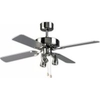
DNHD42 - Fan BESTRON - Free user manual and instructions
Find the device manual for free DNHD42 BESTRON in PDF.


| Product type | Ceiling fan |
| Brand | Bestron |
| Model | DNHD42 |
| Power supply | 220-240 V ~ 50 Hz |
| Number of speeds | 3 |
| Reverse rotation function | Summer/winter switch (clockwise/counterclockwise) |
| Integrated lighting | 3 halogen spots |
| Bulb type | Halogen (not included) |
| Minimum mounting height | 2.30 m |
| Number of blades | 4 |
| Blade material | Metal with coating |
| Mounting mode | With or without separator tube |
| Controls | Pull cord (on/off and speeds) |
| Balancing function | Balancing clips and weights included |
| Protection | Mounting plate with grounding |
| Cleaning | Damp cloth, vacuum for blades |
| Safety | Disconnect before cleaning, do not immerse |
| Warranty | 60 months (parts and labor) |
| Repairs | By qualified technician only |
| Usage | Household only, indoor |
| Package contents | Motor, blades, brackets, tube, spot frame, balancing kit, screws |
Frequently Asked Questions - DNHD42 BESTRON
User questions about DNHD42 BESTRON
0 question about this device. Answer the ones you know or ask your own.
Ask a new question about this device
Download the instructions for your Fan in PDF format for free! Find your manual DNHD42 - BESTRON and take your electronic device back in hand. On this page are published all the documents necessary for the use of your device. DNHD42 by BESTRON.
USER MANUAL DNHD42 BESTRON
natural_image
Abstract black arrow symbol pointing right, no text or symbols presentBESTRON®
DNHD42

natural_image
Line drawing of a five-petal ceiling fan with adjustable blades and a top hub (no text or symbols)natural_image
Technical line drawing of mechanical components with no visible text or symbolsnatural_image
Technical line drawing of a mechanical assembly with multiple components and mounting holes (no text or symbols)MONTAGE - Montage ventilatorbladen
natural_image
Technical line drawing of a mechanical assembly with two views: top shows a curved component with mounting holes, bottom shows a circular base with a central component and attached bracket (no text or symbols)natural_image
Technical diagram of a mechanical assembly with pulleys, gears, and a motor (no text or labels)MONTAGE - Balanceren van de ventilator
MONTAGE - Zubehörliste
natural_image
Technical line drawing of mechanical components including gears and a pump assembly (no text or symbols)natural_image
Technical line drawing of a mechanical assembly with multiple components and mounting holes (no text or symbols)natural_image
Technical line drawing of a mechanical assembly with two views: top shows a curved component, bottom shows a circular base with a central knob (no text or symbols)natural_image
Technical line drawing of a mechanical assembly with multiple circular components and a central hub (no text or symbols)natural_image
Technical line drawing of a mechanical assembly with multiple components and mounting holes (no text or symbols)natural_image
Technical line drawing of a mechanical assembly with two views: top shows a curved component with mounting holes, bottom shows a cylindrical component inserted into a flanged housing (no text or symbols)CONDITIONS DE GARANTIE
DÉCLARATION DE CONFORMITÉ CE
SAFETY INSTRUCTIONS - General
- Please read these instructions carefully and retain them for future reference.
- Use this appliance solely in accordance with these instructions.
- This appliance can be used by children older than 8 years and persons with reduced physical, sensory or mental capabilities or lack of experience and knowledge, but only if they have been given supervision or instruction concerning use of the appliance in a safe way and understand the hazards involved.
- Children should be supervised to ensure that they do not play with the appliance.
- Cleaning and maintenance must not be done by children, except if they are older than 8 years and supervised.
- Keep the appliance and the cable out of reach of children under 8 years.
- Have any repairs carried out solely by a qualified electrician. Never try to repair the appliance yourself.
SAFETY INSTRUCTIONS - Electricity and heat
- Verify that the mains voltage is the same as that indicated on the type plate on the appliance before use.
- Plug the appliance into an earthed wall socket.
• Always remove the plug from the socket when the appliance is not in use.
• Always remove the plug from the wall socket by pulling on the plug, not the power cord. - Check the appliance's power cord regularly to make sure it is not damaged. Do not use the appliance if the power cord is damaged. Have a damaged power cord replaced by qualified service department.
- When using an extension lead always make sure that the entire cable is unwound from the reel.
• Use solely approved extension leads. - Avoid stumbling over the extension lead or power cord.
• Make sure that the appliance and the power cord do not come in contact with sources of heat, such as a hot hob or naked flame.
• Make sure that the switch, the power cord and plug do not come in contact with water.
SAFETY INSTRUCTIONS - During use
• Never use the appliance outdoors.
• Never use the appliance in a humid room.
• Fit the fan at a height of at least 2.3 metres.
• Make sure your hands are dry when touching the appliance.
• Make sure the rotating blades cannot touch you or other objects.
- Turn off the appliance if you discover a fault during use or when cleaning the appliance.
- Never immerse the appliance in water, or in other liquids.
OPERATION - General
The appliance is intended only for domestic use, not for professional use.
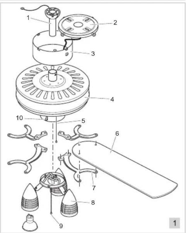
- Distance sleeve
- Attachment plate
- Protective cover
- Motor housing
- Speed control switch
- Fan blades
- Assembly bracket
- Light fitting with three halogen spotlights
- On/Off switch for the lights
- Summer/winter switch
OPERATION - Before use for the first time
Remove the fan from the packaging.
ASSEMBLY - Parts list
| Diagram Component Number | |||
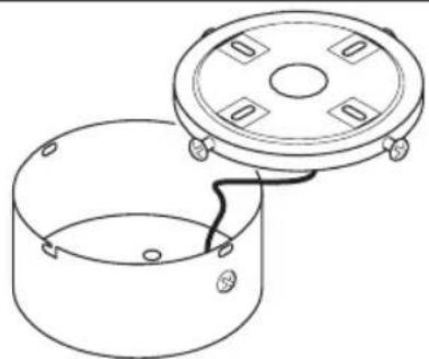 | Protective cover with attachment plate | 1 | |
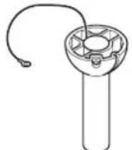 | Distance sleeve | 1 | |
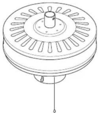 | Motor housing | 1 | |
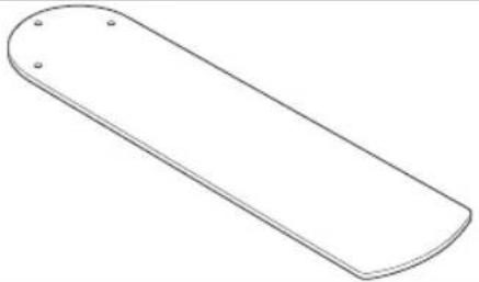 | Fan blades | 4 | |
 | Assembly brackets | 4 | |
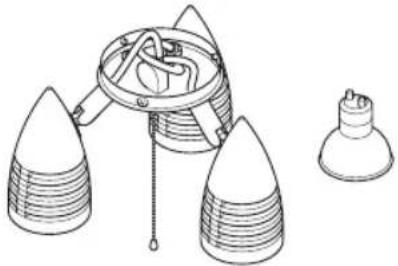 | Light fitting with three halogen lights | 1 | |
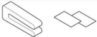 | Balancing clipTwo balancing weights | 1 + 2 | |
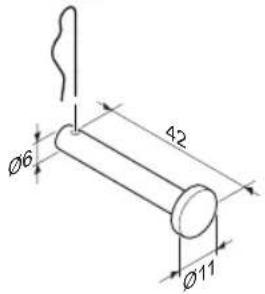 | Locking pin with spring clip | 1 + 1 | |
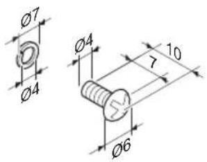 | Short M4 bolt with spring washer | 3 + 3 | |
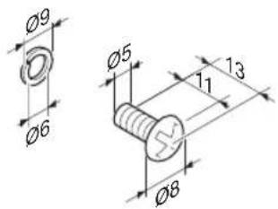 | Medium-length M5 bolt with spring washer | 8 + 8 | |
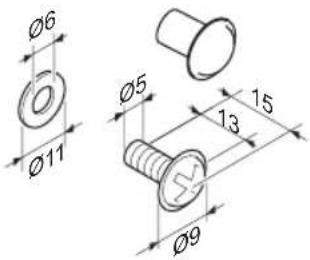 | Long M5 bolt with cardboard washer | 12 + 12 | |
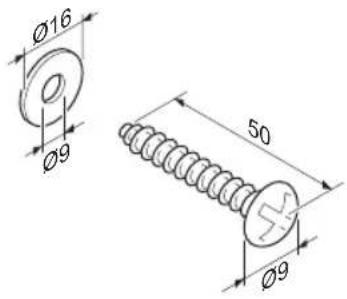 | Screw with washer | 2 + 2 | |
ASSEMBLY - Assembly with the distance sleeve
If you wish to use the ceiling fan with the distance sleeve, follow the instructions given below. Otherwise, see "Assembly without the distance sleeve". Take the following parts from the packaging.
- Protective cover with attachment plate
- Distance sleeve
- Motor housing
-
Locking pin with spring clip
-
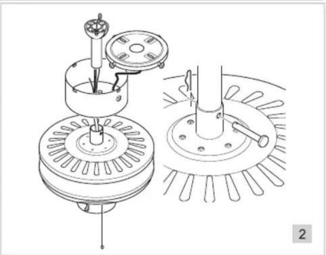
Insert the metal end of the distance sleeve into the protective cover.
- Insert the four wires which come out of the motor housing into the bottom of the distance sleeve.
- Pull the wires out of the metal end of the distance sleeve.
- Insert the metal end of the distance sleeve into the attachment of the motor housing. Make sure the holes in the distance sleeve are aligned
- Attach the distance sleeve to the motor housing.
- Insert the locking pin all the way through the attachment of the motor housing.
- Lock the locking pin by attaching the spring clip.
natural_image
Technical line drawing of mechanical components including gears and a pump assembly (no text or symbols)ASSEMBLY - Assembly without the distance sleeve
If you wish to use the ceiling fan without the distance sleeve, follow the instructions given below. Take the following parts from the packaging:
- Protective cover with attachment plate
-
Motor housing
• 3 short M4 bolts and 3 spring washers -
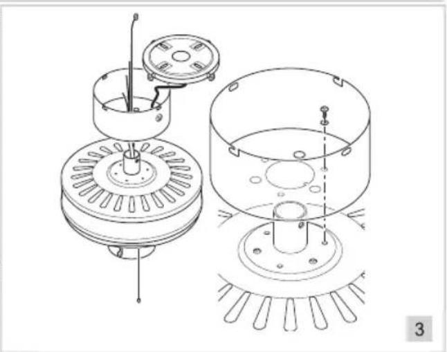
Take a short M4 bolt and place a spring washer over the screw thread.
- Repeat this for the other two bolts.
- Insert the four wires which come out of the motor housing through the top of the protective cover.
- Rotate the protective cover so that the large holes are aligned with the heads of the three bolts.
- Attach the protective covering using the three bolts and the spring washers. Tighten the bolts.
natural_image
Technical line drawing of a mechanical assembly with multiple components and mounting holes (no text or symbols)ASSEMBLY - Fitting the fan blades
Take the following parts from the packaging:
- Fan blades
-
Assembly brackets
• 12 medium-length M5 bolts and 12 cardboard washers
• 8 long M5 bolts and 8 washers
• 4 paper gaskets -
Take a medium-length M5 bolt and place a green cardboard washer over the screw thread.
- Repeat this for the other 11 bolts.
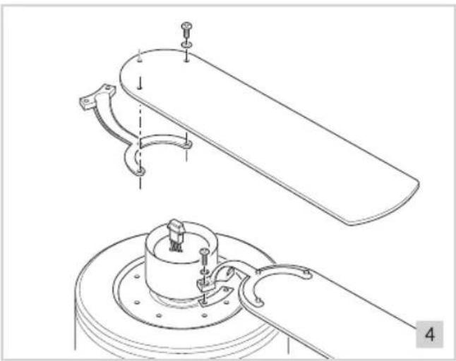
- Decide which side of the fan blade is the side you want to be visible.
- Hold the fan blade with the side which must be seen from below against the flat side of an assembly bracket. Make sure the holes in the fan blade are aligned with the holes in the assembly bracket.
-
Insert a bolt with a cardboard washer through all three holes in the fan blade.
-
Tighten the three bolts.
- Repeat this for the other three fan blades.
- Take a long M5 bolt and place a spring washer over the screw thread.
- Place a paper gasket over the screw thread and screw the bolt firmly onto the motor housing.
- Repeat this for the other two bolts.
- Screw the remaining three fan blades into place.
natural_image
Technical line drawing of a mechanical assembly with two views: top shows a curved component with mounting holes, bottom shows a cylindrical component inserted into a housing (no text or symbols)ASSEMBLY - Connecting the wires of the motor housing
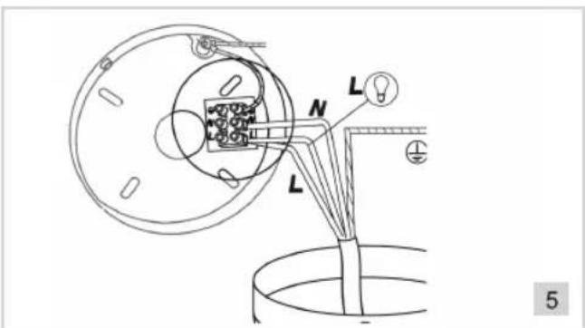
- Connect the wires in the motor housing to the connector in the attachment plate. Pay attention to the following coding:
| Wire colour | Connect to |
| Brown L | |
| Blue N | |
| Black L |
- Attach the eye of the green/yellow earth wire to the attachment plate.
ASSEMBLY - Connecting the wires of the motor housing
Take the following parts from the packaging:
• Two screws with washers
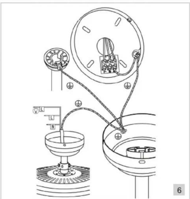
- Unscrew two bolts on opposite sides of the attachment plate.
If a distance sleeve is used, make sure the cam in the protective cover falls into the groove at the top of the distance sleeve.
- Secure the attachment plate to the ceiling using two attachment screws with washers.
- Hang the fan from the hook of the attachment plate. This will make it easier to connect the fan.
- Connect the wires hanging down from the ceiling to the connector in the attachment plate.
- Attach the eye of the green/yellow earth wire in the motor housing to the protective cover.
- Attach the eye of the green/yellow earth wire of the distance sleeve to the protective cover.
- Attach the eye of the green/yellow earth wire of the protective cover to the attachment plate.
Pay attention to the following coding:
| Wire colour Connect to | ||
| Brown or black L | ||
| Blue N | ||
| 2x yellow/green (motor housing and distance sleeve) | Earth Not always present, but recommended! | |
-
Remove the fan from the hook of the attachment plate.
-
Attach the motor housing to the attachment plate by placing the two grooves in the protective cover over the bolts in the attachment plate. Slightly rotate the protective cover anticlockwise.

Make sure the rotating fans cannot touch you or other objects.
-
Tighten the two bolts.
-
Insert the two loose bolts through the grooves in the side of the attachment cover and screw them firmly into the attachment plate.
ASSEMBLY - Installing the light fitting and the halogen lights
Take the following parts from the packaging:
- Light fitting
• Three halogen lights
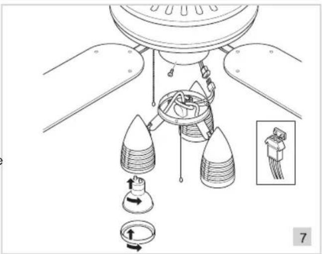
The light fitting is attached to the underside of the ceiling fan.
- Remove the circlip from the halogen spotlights.
- Place the halogen light bulbs into the light fitting and screw them in clockwise.
- Place the circlip back on the halogen spotlights.
- Remove the plug from the motor housing's socket.
- Unscrew the three bolts from the side of the light fitting.
-
Fit the light fitting in place.
-
Insert the light fitting's plug into the motor housing's socket.
- Insert the light fitting into the bottom of the motor housing and secure it in place by tightening the three bolts.
ASSEMBLY - Balancing the fan
Take the following parts from the packaging:
- Balancing clip
- Two balancing weights
During manufacture, we ensure that your ceiling fan is of the highest possible quality. However, the fan may sometimes not be balanced correctly. This is usually due to irregularities in the fan blades or the attachment brackets. If the fan is not balanced, check the following:
- The attachment plate must be fitted as close as possible against the ceiling.
- If the distance sleeve is used, then this must be securely fixed. If you change anything to the distance sleeve, make sure you also re-tighten the screw.
• The fan blades must be firmly attached to the assembly brackets. - The assembly brackets must be firmly attached to the motor housing.
- The fan blades must be evenly distributed when viewed from below. If necessary, carefully reposition them.
- The ends of the fan blades must all be the same distance from the ceiling. Measure this by placing ruler against the ceiling and measuring the distance from the ceiling to the end of a fan blade. Do this for all four fan blades. If one of the fan blades is not the same distance from the ceiling as the others, correct it by carefully bending the blade.
If the steps given above do not balance the ceiling fan, then carry out the procedure given below.
- Set the fan to the speed which causes it to wobble the most.
- Turn off the fan and place the balancing clip halfway along one of the blades.
- Turn on the fan again and check whether the wobbling has increased or decreased.
- Turn off the fan again and place the balancing clip halfway along another one of the blades.
- Turn on the fan again and check whether the wobbling has increased or decreased.
- Repeat this for the other fan blades and determine for which blade the wobbling decreases the most.
- Place the balancing clip back on this fan blade, as close as possible to the assembly bracket.
- Turn on the ceiling fan and check the wobbling.
- Turn the ceiling fan off again and slide the balancing clip towards the end of the blade. Repeat this until the fan wobbles the least.
- Remove the balancing clip and stick the two balancing weights on either side of the blade at this location.
OPERATION - Use

The fan blades must be completely still before changing the position of the summer/ winter switch.
- Tilt the fan to the required angle. You can set the fan blades:
a. So that they rotate clockwise. Set the summer/winter switch to the top position (winter position). b. So that they rotate anticlockwise. Set the summer/winter switch to the bottom position (summer position).
- Turn on the fan by pulling the speed control's cord.
a. 1st positon: the fan operates at low speed
b. 2nd position: the fan operates at normal speed.
c. 3rd position: the fan operates at high speed.
- Turn off the fan by pulling the speed control's cord again.
CLEANING AND MAINTENANCE
- Allow the halogen lights to cool down before cleaning or carrying out maintenance on the fan.
- Clean the exterior of the ceiling fan with a damp cloth.
• Dry the ceiling fan with a dry, soft cloth.

- Disconnect the fuse group concerned before cleaning the ceiling fan.
Make sure that the electrical connections do not become damp.
- Never use corrosive or scouring cleaning agents or sharp objects (such as knives or hard brushes) to clean the appliance.
After a while, dust can accumulate on the fan blades. Remove the dust with a hand brush and/or a vacuum cleaner.
THE ENVIRONMENT
- Dispose of packaging material, such as plastic and boxes, in the appropriate waste containers.
When this product reaches the end of its useful life do not dispose of it by putting it in a dustbin; hand it in at a collection point for the reuse of electrical and electronic equipment. Please refer to the symbols on the product, the user's instructions or the packaging.
- The materials can be re-used as indicated. Your help in the re-use, recycling or other means of making use of old electrical equipment will make an important contribution to the protection of the environment.
- Contact your municipality for the address of the appropriate collection point in your neighbourhood.
GUARANTEE TERMS
The importer guarantees the appliance against defects caused by manufacturing and/or material faults for 60 months from the date of purchase, subject to the following conditions.
- No charges will be made for labour costs or materials during the warranty period. Any repairs carried out during the warranty period do not extend the warranty period.
-
The importer automatically becomes the owner of any faulty parts that he replaces or a faulty appliance (in the event of replacement of the appliance).
-
All claims submitted under warranty must be accompanied by the original bill of sale.
-
Claims under warranty must be submitted to the dealer where the appliance was purchased or to the importer.
-
The warranty is issued solely to the first purchaser and cannot be transferred.
-
The warranty does not cover damage caused by:
a. Accidents, incorrect use, wear and/or neglect.
b. Faulty installation and/or use in a manner contravening the prevailing legal, technical or safety regulations.
c. Connection to a mains voltage other than the voltage specified on the type plate.
d. Unauthorized modifications.
e. Repairs carried out by third parties.
f. Careless transport, i.e. without suitable packaging materials or protection.
- No claims may be made under this warranty for:
a. Losses incurred during transport.
b. The removal or changing of the appliance's serial number.
-
The guarantee does not cover power cords, lamps or glass parts.
-
No claims can be submitted under this warranty for damage other than the repair or replacement of faulty parts. The importer can never be held responsible for any consequential loss or damage or any other consequences, resulting either directly or indirectly from the appliance supplied by the importer.
-
In case of claims under guarantee you can contact your dealer where the appliance is purchased. Bestron offers you also the possibility to send the appliance directly to our Service Department. Do not send your appliance without consulting us. The package may be refused and any any costs will be for your account. Please contact the Service Department and they will tell you how to pack and send the appliance.
-
This appliance is not suitable for professional use.
SERVICE
If a fault should occur please contact the BESTRON service department: www.bestron.com/service
CE DECLARATION OF CONFORMITY
This product conforms to the essential requirements of the following EU safety directives:
• EMC Directive 2004/108/EC
• Low Voltage Directive 2006/95/EC
R. Neyman Quality control
natural_image
Technical line drawing of mechanical components including gears and a shaft assembly (no text or symbols)natural_image
Technical line drawing of a mechanical assembly with multiple components and mounting holes (no text or symbols)natural_image
Technical line drawing of a mechanical assembly with two views: top shows a curved component, bottom shows a circular base with a central component (no text or symbols)natural_image
Technical line drawing of a mechanical assembly with pulleys and components (no text or symbols)
- BESTRON®
- MONTAGE - Montage ventilatorbladen
- MONTAGE - Balanceren van de ventilator
- MONTAGE - Zubehörliste
- CONDITIONS DE GARANTIE
- DÉCLARATION DE CONFORMITÉ CE
- SAFETY INSTRUCTIONS - General
- SAFETY INSTRUCTIONS - Electricity and heat
- SAFETY INSTRUCTIONS - During use
- OPERATION - General
- OPERATION - Before use for the first time
- ASSEMBLY - Parts list
- ASSEMBLY - Assembly with the distance sleeve
- ASSEMBLY - Assembly without the distance sleeve
- ASSEMBLY - Fitting the fan blades
- ASSEMBLY - Connecting the wires of the motor housing
- ASSEMBLY - Installing the light fitting and the halogen lights
- ASSEMBLY - Balancing the fan
- OPERATION - Use
- CLEANING AND MAINTENANCE
- THE ENVIRONMENT
- GUARANTEE TERMS
- SERVICE
- CE DECLARATION OF CONFORMITY
Brand : BESTRON
Model : DNHD42
Category : Fan