
Summer Breeze DFS45SCO - Fan BESTRON - Free user manual and instructions
Find the device manual for free Summer Breeze DFS45SCO BESTRON in PDF.

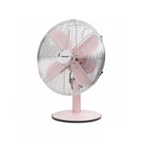
| Product type | Pedestal fan |
| Brand | Bestron |
| Model | Summer Breeze DFS45SCO |
| Power supply | 220-240 V ~ 50 Hz |
| Number of speeds | 3 (I, II, III) |
| Oscillation | Yes, 90° angle (left-right sweep) |
| Adjustable height | Yes, telescopic pole with lock |
| Tilt | Yes, adjustable forward and slightly downward |
| Blade material | Metal |
| Protection grille | Front and rear, with hook and closure staples |
| Cleaning | Disassembly possible for cleaning blades and grilles; use a damp cloth, no harsh detergents |
| Safety | Do not use near water, do not cover, unplug before cleaning, do not repair yourself |
| Use | Domestic only, indoor |
| Warranty | 60 months (5 years) from date of purchase |
| Weight | Approximately 3.5 kg (estimate) |
| Dimensions (approximate) | Max height approx. 130 cm, grille diameter approx. 45 cm |
| Power | Approximately 45 W (estimate) |
| Included accessories | Telescopic pole, front/rear grilles, blades, mounting screws |
| Repairability | Call a qualified technician; spare parts available via Bestron after-sales service |
| Standards | Compliant with EMC directives 2014/30/EU, Low Voltage 2014/35/EU, RoHS 2011/65/EU |
Frequently Asked Questions - Summer Breeze DFS45SCO BESTRON
User questions about Summer Breeze DFS45SCO BESTRON
0 question about this device. Answer the ones you know or ask your own.
Ask a new question about this device
Download the instructions for your Fan in PDF format for free! Find your manual Summer Breeze DFS45SCO - BESTRON and take your electronic device back in hand. On this page are published all the documents necessary for the use of your device. Summer Breeze DFS45SCO by BESTRON.
USER MANUAL Summer Breeze DFS45SCO BESTRON
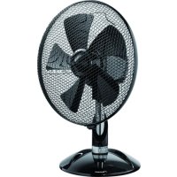
natural_image
Exterior view of a stainless steel TV fan with visible blades and base (no text or symbols)


DFS45SCO INSTRUCTION MANUAL
DE
Bedienungsanleitung
FR
Mode d'emploi
NL
Handleiding
EN
Instruction manual
IT
R. Neyman
Quality control
FUNKTION - Allgemein
natural_image
Technical line drawing of a mechanical assembly with concentric circles and a separate component (no text or symbols)MONTIEREN - Ventilator montieren
3
natural_image
Mechanical assembly diagram showing a valve mechanism with gears and bolts (no text or labels)natural_image
Diagram of a scientific apparatus with a spherical object and two curved arrows indicating motion or force directions (no text or symbols present)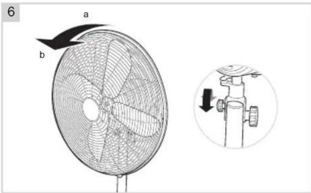
natural_image
Technical line drawing of a multi-tiered fan with a mounted propeller and fan blade assembly (no text or symbols)ACHTUNG:
DÉCLARATION DE CONFORMITÉ CE
natural_image
Technical line drawing of a mechanical assembly with concentric circles and a separate component (no text or symbols)natural_image
Mechanical assembly diagram showing a mechanical component with gears and springs, no text or symbols presentnatural_image
Diagram of a scientific apparatus with a spherical object and two curved arrows indicating motion or force directions (no text or symbols present)
NETTOYAGE ET ENTRETIEN
natural_image
Technical line drawing of a multi-tiered fan with a mounted device, showing fan blades and mounting bracket (no text or symbols)ATTENTION:
WAT U MOET WETEN OVER DIT APPARAAT
R. Neyman
Quality control
WERKING - Algemeen
natural_image
Mechanical assembly diagram showing a mechanical component with gears and springs, no text or symbols presentnatural_image
Diagram of a scientific apparatus with a spherical object and two curved arrows indicating motion or force directions (no text or symbols present)
REINIGING EN ONDERHOUD
natural_image
Technical line drawing of a multi-tiered fan with an air vent and mounted device (no text or symbols)LET OP:
Congratulations with the purchase of this Bestron product. These instructions tell you how the product works and how to use it. Read the instructions carefully before you start using the appliance. Only use the appliance in the manner described in the instructions. Keep these instructions in a safe place for future reference.
Defects:
If the appliance is defective, do not try to repair it yourself. Always have a qualified mechanic carry out any repairs.
Children:
- This appliance may be used by children over the age of 8 years old and persons with reduced physical, sensory or mental capabilities or lack of experience and know-how, but only if supervised or if they have been instructed on how to use the appliance safely and are aware of its potential dangers.
• Children are not allowed to clean and maintain the appliance, except if they are over the age of 8 years old and supervised. - Keep the appliance and the cable out of reach of children under the age of 8 years old.
- Keep an eye on children to ensure that they do not play with the appliance.
WHAT YOU SHOULD KNOW ABOUT ELECTRICAL APPLIANCES
- Check that the mains voltage corresponds with that shown on the rating plate of an electrical appliance before you use it.
- Check that the socket to which you connect the electrical appliance is earthed.
• Always install electrical appliances on a stable and level surface where it cannot fall over. - Certain parts of an electrical appliance may become warm or sometimes hot. Do not touch them as you may burn yourself.
• Make sure your hands are dry when you touch an electrical appliance, a cord or a plug. - Electrical appliances must be able to lose their heat to avoid fire hazards. Therefore, make sure that the appliance has sufficient clearance around it and that it does not come into contact with flammable materials. Electrical appliances must never be covered.
- Make sure that electrical appliances, cords or plugs do not come into contact with water.
Never immerse electrical appliances, cords or plugs in water or any other liquid.
- Do not touch electrical appliances if they have fallen in the water. Immediately pull the plug out of the socket. Stop using the appliance.
• Make sure that electrical appliances, cords and plugs do not come into contact with heat sources, such as a hot hob or open fire. - Never let cords hang over the edge of the sink, a worktop or a table.
• Always remove plug from the socket when you are not using the electrical appliance. - Remove the plug from the socket by pulling the plug itself and not the cord.
- Regularly check if the cord of the electrical appliance is not damaged. Do not use the electrical appliance if the cord shows signs of damage. If the cord is damaged, it should be replaced by the manufacturer, a technical service provider or a person with an equivalent qualification, to avoid any danger.
- The appliance may not be switched on with the aid of an external time switch, or by a separate system with remote control.
WHAT YOU SHOULD KNOW ABOUT THIS APPLIANCE
- Be careful when using the appliance outdoors.
- Never use the appliance in damp or wet locations.
- Thoroughly clean the appliance after use (see Cleaning and Maintenance).
- Never use the appliance near an open window; rain coming through the window could come into contact with the appliance and cause a short circuit.
- Put the fan on a horizontal and clean floor. Make sure that the appliance is unobstructed.
• Make sure that objects cannot contact the fan blades. - Do not cover the appliance whilst it is in use.
ENVIRONMENT
- Dispose of packaging material such as plastic and cardboard boxes in the designated containers.
Do not dispose of this product as normal domestic waste at the end of its life, but hand it in at a collection point for the reuse of electric and electronic equipment. Look for the symbol on the product, the user instructions or the packaging showing the type of waste.
- The materials can be used as indicated. By helping us reuse and process the materials or otherwise recycle the old equipment, you will be making an important contribution towards the protection of the environment.
- Your municipality can tell you where to find the designated waste collection point in your neighbourhood.
CE DECLARATION OF CONFORMITY
This product conforms to the requirements of the following European Directives on safety:
• EMC Directive 2014/30/EU
- Low Voltage Directive 2014/35/EU
• RoHS Directive 2011/65/EU
R. Neyman
Quality control
OPERATION - General
The appliance is intended only for domestic use, not for professional use.
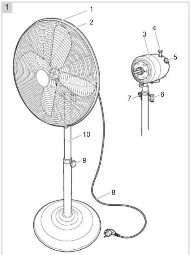
- Fan housing
- Fan blades
- Motor housing
- Oscillation button
- Speed dial
- Fan/stand attachment bolt
- Angle-adjustment knob
- Power cord and plug
- Height lock
- Telescopic stand
OPERATION - Before first use
Remove the fan from the packaging and remove all packaging materials.
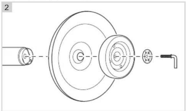
MONTAGE - Assembling the stand
- Remove the "L" shape screw and small silver metal disk from the end of rod.
- Insert the rod into the floor plate, put the weight and small silver metal disk onto the floor plate.
- Use the "L" shape screw to fasten all parts together.
natural_image
Technical line drawing of a mechanical assembly with concentric circles and a shaft (no text or symbols)MONTAGE - Assembling the fan
3
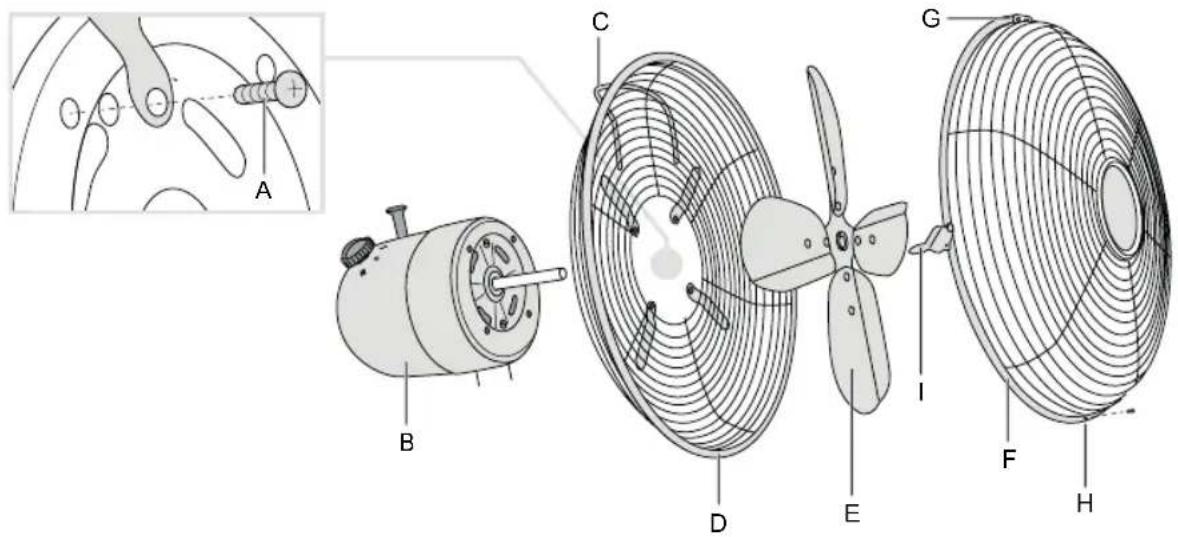
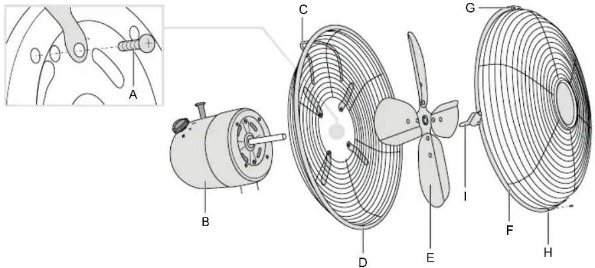
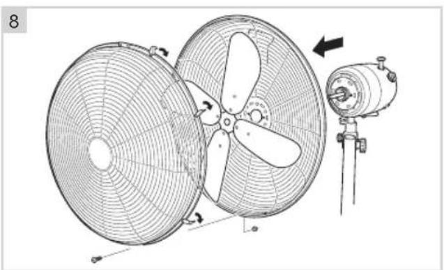
- Unscrew the 4 screws (see figure 3A) from the motor housing (3B).
- Place the back of the fan basket (with handle) (3D) on the shaft of the motor housing (3B), with the handle (3C) at the top.
- Secure the back of the fan basket with 4 screws (3A).
- Slide the fan blades (3E) onto the shaft and fasten the screw.
- Hang the hook on the front half of the fan housing (3F) on the rear half of the fan housing.
- Fit the attachment bolt through the hole at the bottom of the front half and rear half of the fan housing (3H) and tighten the bolt.
- Close the locking clamps (31) over the rim of both halves of the fan housing.
4
natural_image
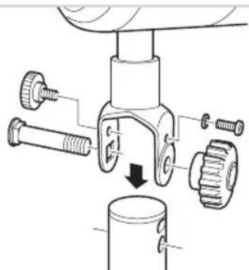
Mechanical assembly diagram showing a valve mechanism with gears and bolts (no text or labels)- Remove the attachment bolt and knob.
- Loosen the knob for the tilt adjustment and the tilt-adjustment locking screw sufficiently to allow the bracket to fit onto the stand.
- Fit the attachment bolt through the motor support and the stand, and tighten the knob.
- Fit the locking screw into the recess in the stand.
- Fit the tilt-adjustment knob. The knob will fit into the deep recess in the stand.
natural_image
Diagram of a scientific apparatus with a spherical object and two curved arrows indicating motion or force directions (no text or symbols present)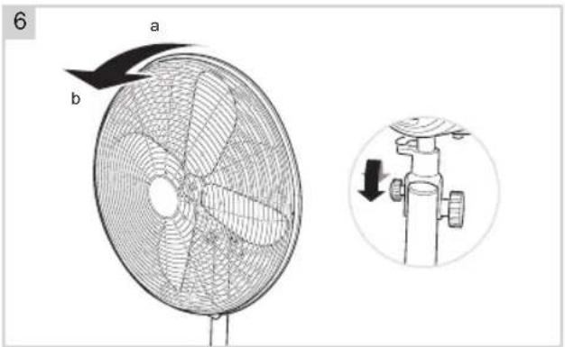
- Set the fan on the floor, on a level surface.
-
Adjust the stand to the required height. To do so, loosen the height lock (anticlockwise). Adjust the stand to the required height, and tighten the height lock (by turning it clockwise).
-
Tilt the fan to the required angle. You can set the fan: a. to blow horizontally (position a) or angled slightly downwards (position b). Tilt the ventilator housing and motor housing to the required angle. b. to oscillate from left to right (with a sweep of 90°). This will ventilate much of the room. Press the oscillation button on the motor housing fully in. c. remain in the same position whilst the fan is turning. This will ventilate one area. Pull out the oscillation button until you hear it click.
-
Put the plug into the wall socket.
-
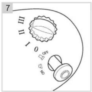
Switch on the fan by turning the speed dial. a. Position 'I': the fan operates at low speed. b. Position 'II': the fan operates at normal speed. c. Position 'III': the fan operates at high speed.
-
Stop the fan by turning the speed dial to position '0'.
CLEANING AND MAINTENANCE
Over the course of time dust can accumulate between the spokes in the fan housing, and on the fan blades. Always begin by trying to remove the dust with a brush and/or vacuum cleaner. If this does not remove all the dust you can always dismantle the fan and clean it.
- Remove the plug from the wall socket.
- Use a small crosshead screwdriver to loosen the screw at the bottom of the fan housing; hold the bolt at the rear of the fan housing to prevent it from turning.
- Remove the front half of the fan housing.
-
Hold the fan blades to prevent them from turning, and use a small crosshead screwdriver to loosen the locking screw. Remove the fan blades from the shaft.
-
Use a crosshead screwdriver to loosen the screws from the motor housing and then remove the housing.
- Clean the dismantled parts and the base with a damp cloth. Dry thoroughly with a dry cloth.
- Clean the motor housing with a dry cloth.
natural_image
Technical line drawing of a two-blade fan assembly with a mounted motor, showing fan blades and mounting bracket (no text or symbols)WARNING:
- Verify that the appliance is not connected to the power supply before you clean it.
- Never use corrosive or scouring cleaning agents or sharp objects (such as knives or hard brushes) to clean the appliance.
- Be careful not to cut yourself on the sharp edges of the fan blades.
Reassemble the fan using the procedure given under by 'Assembling the fan'
WARRANTY CONDITIONS
Bestron offers a 60-month warranty on this equipment against defects resulting from manufacturing and/or material errors, subject to the following conditions.
- No labour or material costs will be charged during this warranty period.
- Any repairs carried out under the warranty will not extend the warranty period.
- Faulty parts, or in the event of exchange, the faulty equipment itself, will automatically become the property of Bestron.
- The warranty is valid for the first buyer only and is non-transferable.
- The warranty is not valid for damage caused by:
- Accidents
- Improper use
- Wear and tear
- Neglect
- Faulty installation
- Connection to a different mains voltage than indicated on the type plate
• Unauthorised changes
• Repairs carried out by unqualified third parties - Use in violation with the applicable statutory, technical or safety standards
-
Careless transport without suitable packaging or other protection
-
Warranty cannot be claimed:
-
For damage during transport
• If the serial number of the appliance is removed or changed -
Items excluded from warranty are:
-
Cords
- Lamps
- Glass parts
- The warranty does not entitle the purchaser to compensation for any damage other than replacement or repair of the faulty parts. Bestron cannot in any event be held liable for any indirect or consequential losses caused by or in relation to the equipment it has provided.
- Claims under a warranty may only be submitted to your (online) retailer or directly to the Bestron Service Department. Never send items without being asked to. We may refuse the parcel and you will be liable for the costs. Contact us first and we tell you how the appliance should be packaged and sent. Each claim under a warranty must be accompanied by the relevant receipt.
SERVICE
If an unexpected problem occurs, please contact the BESTRON service department:
www.bestron.com/service
COMPLIMENTI!
natural_image
Mechanical assembly diagram showing a gear and shaft assembly with a downward arrow indicating motion (no text or symbols present)natural_image
Diagram of a scientific apparatus with a spherical object and two curved arrows indicating motion or force directions (no text or symbols present)
natural_image
Technical line drawing of a two-blade fan with propeller and air vent, showing mechanical assembly (no text or symbols)natural_image
Technical line drawing of a mechanical assembly with concentric circles and a separate component (no text or symbols)natural_image
Mechanical assembly diagram showing a valve mechanism with gears and bolts (no text or labels)natural_image
Diagram of a scientific apparatus with a spherical object and two curved arrows indicating motion or force directions (no text or symbols present)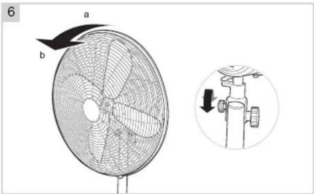
LIMPIEZA Y MANTENIMIENTO
natural_image
Technical line drawing of a two-blade fan with a propeller and mounted fan assembly (no text or symbols)ATTENZIONE:
NEED HELP? CHAT WITH US! WHATSAPP CUSTOMER SERVICE

BESTRON.COM/WHATSAPP
- DFS45SCO INSTRUCTION MANUAL
- FUNKTION - Allgemein
- MONTIEREN - Ventilator montieren
- ACHTUNG:
- DÉCLARATION DE CONFORMITÉ CE
- NETTOYAGE ET ENTRETIEN
- ATTENTION:
- WAT U MOET WETEN OVER DIT APPARAAT
- WERKING - Algemeen
- REINIGING EN ONDERHOUD
- LET OP:
- Defects:
- Children:
- WHAT YOU SHOULD KNOW ABOUT ELECTRICAL APPLIANCES
- WHAT YOU SHOULD KNOW ABOUT THIS APPLIANCE
- ENVIRONMENT
- CE DECLARATION OF CONFORMITY
- OPERATION - General
- OPERATION - Before first use
- MONTAGE - Assembling the stand
- MONTAGE - Assembling the fan
- CLEANING AND MAINTENANCE
- WARNING:
- WARRANTY CONDITIONS
- SERVICE
- COMPLIMENTI!
- LIMPIEZA Y MANTENIMIENTO
- ATTENZIONE:
Brand : BESTRON
Model : Summer Breeze DFS45SCO
Category : Fan