RVC3620N - Rear Camera Pro-User - Free user manual and instructions
Find the device manual for free RVC3620N Pro-User in PDF.
| Product type | Wireless rear view camera |
| Brand | Pro-User |
| Model | RVC3620N |
| Camera power supply | 12V DC |
| Camera consumption | <150 mA |
| Camera sensor | CMOS |
| Camera resolution | 640 x 480 pixels |
| Camera lens | 2.4 mm |
| Transmission frequency | 2414-2468 MHz |
| Transmission range | >80 m (open field) |
| Monitor power supply | 12V DC (cigarette lighter plug) |
| Monitor standby consumption | <45 mA |
| Monitor operating consumption | <350 mA |
| Screen size | 3.5 inches |
| Screen resolution | 320 x 240 pixels |
| Operating temperature | -10°C to +45°C |
| Number of cameras included | 2 |
| Functions | Graduation grid, camera switching, image settings (brightness, contrast, color, orientation) |
| Warranty | 2 years |
| Safety | Do not open the housings, professional installation recommended |
| Monitor attachment | Suction cup on windshield or dashboard |
Frequently Asked Questions - RVC3620N Pro-User
User questions about RVC3620N Pro-User
0 question about this device. Answer the ones you know or ask your own.
Ask a new question about this device
Download the instructions for your Rear Camera in PDF format for free! Find your manual RVC3620N - Pro-User and take your electronic device back in hand. On this page are published all the documents necessary for the use of your device. RVC3620N by Pro-User.
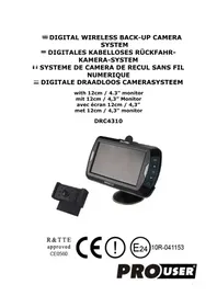
USER MANUAL RVC3620N Pro-User
with 3,5 inch monitor
mit 3,5” Monitor
The Pro-User RVC3620N is member of the family of advanced car back-up systems manufactured by Pro User International Ltd.
The Pro-User Wireless Back-up Cameras and Monitor, when used as described, will improve your ability to see behind your car, camper, trailer, carvans or mini-van. We have taken numerous measures in quality control to ensure that your product arrives in top condition, and will perform to your satisfaction.
Please carefully read and follow the following safety and operating instructions.
IMPORTANT SAFETY INSTRUCTIONS
Before You Install
If you are not confident working with 12 volt DC vehicle wiring, removing and reinstalling interior panels, carpeting, dashboards or other components of your vehicle, contact the vehicle's manufacturer, or consider having the camera system professionally installed.
Interference
This device, as well as all other wireless devices, may be subject to interference. Interference may be caused by cell phones, Bluetooth headsets, Wi-Fi routers, power lines and other various electrical equipment, etc.
Repair
The camera system should not be opened. Any attempt at modification or repair by the user will entail the loss of your guarantee.
PARTS
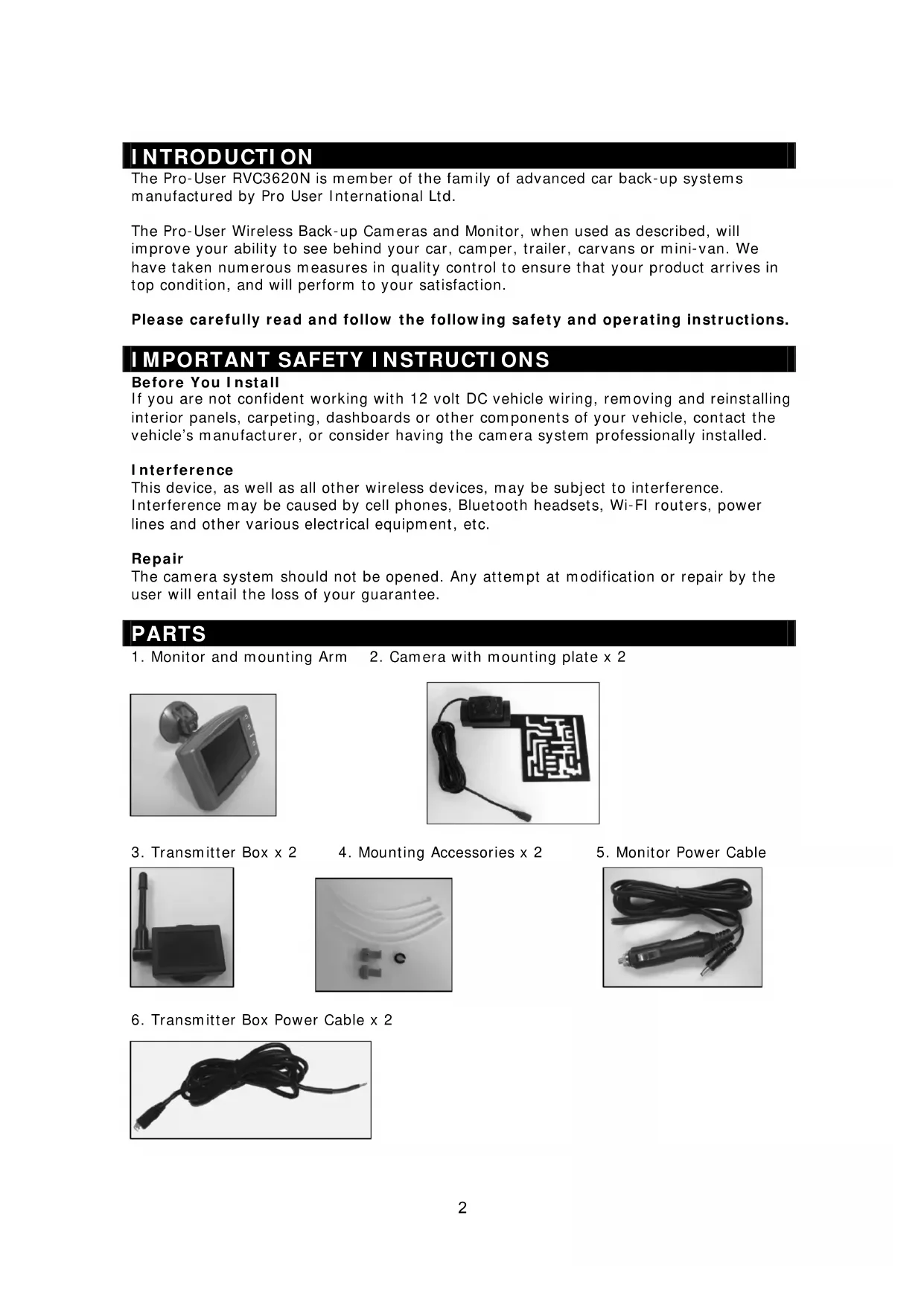
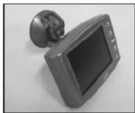
- Monitor and mounting Arm 2. Camera with mounting plate x 2
-
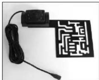
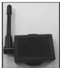
Transmitter Box x 2
-
Mounting Accessories x 2
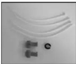
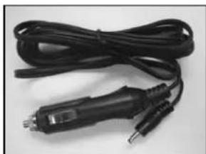
- Monitor Power Cable
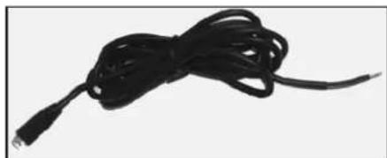
- Transmitter Box Power Cable x 2
INSTALLATION
These instructions do not apply to all vehicles. They are only meant as a general guide due to the number of different makes & models. For vehicle specific questions contact your vehicle's manufacturer.
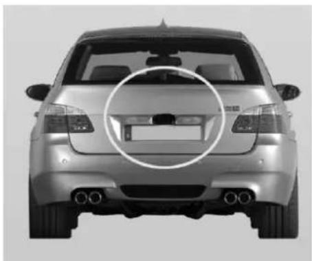
Camera installation
There are several ways to mount the cameras on the back of your vehicle or trailer. But the most convenient is to mount it near the license plate of the vehicle or trailer.
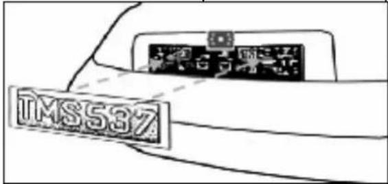
Supplied are two mounting plates that can be fixed behind the license plate, and the mounting plates have been installed in the cameras.
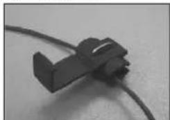
The camera is tiltable, camera angle can be adjusted manually on vertical direction. Make sure that its field of view and detection are not obstructed.
There are two sets of cameras and transmitters, use the same way below to install them on the vehicle and trailer respectively.
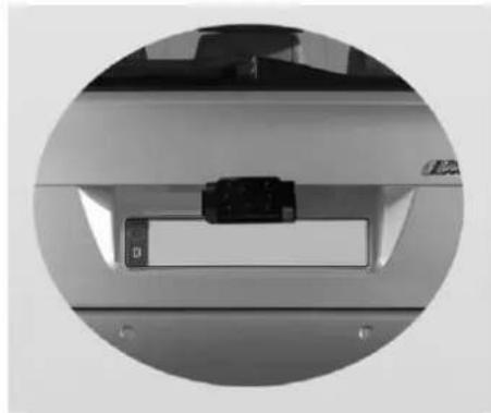
- Remove the rear license plate, and then loosen the license plate bolts/screws.
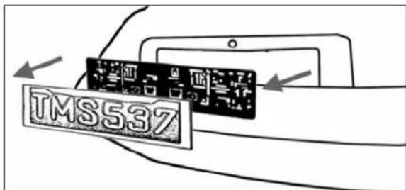
- Position the supplied mounting plate (with camera together) behind the license plate bracket. Secure both license plate bracket and mounting plates with the license plate bracket bolts/screws.

- Mount the license plate on the license plate bracket.
-
Choose a routing path for the camera's power cable through the vehicle's (or trailer's) body to the reverse light circuit. If in doubt, seek professional installation assistance.
-
Some vehicles (or trailer) may have a hole available to pass the wire through, such as where the license plate light is mounted, or you can drill a hole close to where the power cable is attached to the camera. Once you have chosen where the cable will enter the vehicle's (or trailer's) body, remove the camera. If you are able to use an existing opening, skip the next two steps.
-
Before you drill a hole you MUST CHECK and see WHAT IS BEHIND WHERE YOU ARE DRILLING. If there are any vehicle components, such as electrical parts or fuel system components behind where you are drilling, you must take whatever precaution is necessary not to damage them. Remove the license plate and camera before drilling.
-
After you have drilled the hole, insert the supplied grommet, then pass the camera cables through the grommet into the vehicle (or trailer's). You must use the grommet to prevent the metal edge of the hole from cutting the camera cable.
-
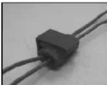
Mount the transmitter box inside the trunk. Connect the camera's power cable and the transmitter box power cable to the transmitter box. NOTICE: Choose position to mount the transmitter boxes as close as possible to the receiver for better signal transmission; The length of the power cables are long enough for routing from the rear end to the front of the vehicle or trailer. The transmitter doesn't comply with weatherproof.
-
Next you'll need to find the vehicle's (or trailer's) reverse lights. Turn the vehicle's ignition key to the accessory position, engage the parking brake and put the car in reverse. Look at the vehicle's tail lights to see where the reverse lights are located, they are the white lights. To locate the reverse light's 12V+ wire it will be necessary to gain access to the rear of the vehicle's (or trailer's) tail light. For help locating the vehicle's (or trailer's) reverse light circuit contact your vehicle's (or trailer's) manufacturer for vehicle specific wiring diagrams.
-
Once you have located the reverse light circuit you will have to route the transmitter box power cable to that location. You must securely fasten the power cable to prevent it from being caught on any vehicle component such as the trunk hinge. Never route the cable on the outside of the vehicle (or trailer)!
-
The reverse light sockets on most vehicles have two wires connected to them. Usually the negative wire is black and the positive wire is a colored wire. If you are uncertain about the wiring, you can use a 12 volt multi-meter available at most auto parts stores to determine which is the positive wire. Follow the manufacturer's instructions for the safe use of the multimeter.
-
After determining which wire is the positive and which is the negative, turn off the ignition key, then remove the battery's negative cable.
-
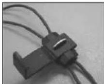
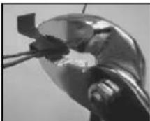
Splice the red wire using the supplied in-line wire connectors to the reverse light's positive (+) wire. Use a set of slip joint pliers to squeeze the TAP and insure good connection.
- Next splice the black wire of the transmitter box power cable to the reverse light's negative (-) wire or ground.
- Replace the reverse light bulb, and then re-install the light socket. Secure all the wires with cable ties or electrical tape.
- Re-attach the negative battery cable to the battery.
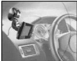
Monitor Installation
When choosing a location to mount the monitor, make sure the monitor is in an area that will not obstruct your vision while driving.
- Before mounting the monitor, clean the mounting surface well.
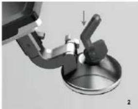
- Position the suction mount to the smooth surface which suits your requirement.
- Press the suction cap against the smooth surface and press the lock down to attach and fix the mount to the surface.
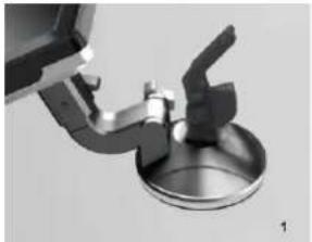
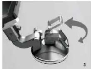
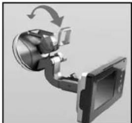
- Snap in the monitor to the suction mount.
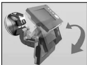
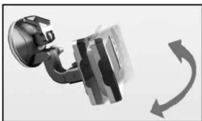
- Adjust the mounting arms to suit your view angle to the monitor and tighten the screws on the mount to fix the position.
- Route the power cable to the vehicle's cigarette lighter socket/12V power outlet. The cable must not interfere with the safe operation of the vehicle.
- Insert the small 12 Volt DC plug of the power cable into the right side of the monitor.
- Plug the 12 Volt cigarette lighter plug into the vehicle's cigarette lighter socket.
To maximize the effectiveness of the suction mount, it is recommended that the application be performed under the following conditions:
- Surface temperature should be between 21 and 38 degrees Celsius.
- Application below 10 degrees should be avoided.
- Application should not occur in direct sunlight.
Mounting should be protected from exposure to direct sunlight for a period of 24 hours.
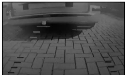
NOTE: UNDER EXTREME BRIGHT LIGHT CONDITIONS, THE SCREEN IMAGE MAY TAKE A FEW SECONDS TO STABLIZE. PLEASE WAIT UNTIL THE IMAGE HAS STABLIZED BEFORE BACKING UP.
System testing
- Reattach the vehicle's negative battery cable.
- Turn the ignition key to the accessory position, do not start the vehicle.
- Engage the parking brake, and then put the shifter in the reverse position.
- Look at the monitor, if the image does not match your rear view mirror press the Image Orientation button on the monitor to correct the image.
- After testing the unit and you are satisfied with the route you have chosen for the cabling, you must permanently install it.
- Route all wires behind interior panels or under carpeting so they are hidden. Use supplied cable ties to neatly gather any excess wire.
OPERATION
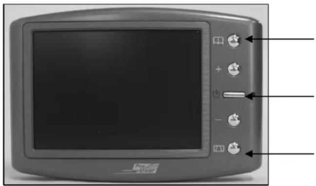
The monitor will automatically turn on when the vehicle is in reverse gear. There are 5 control buttons available for users to have their controls:
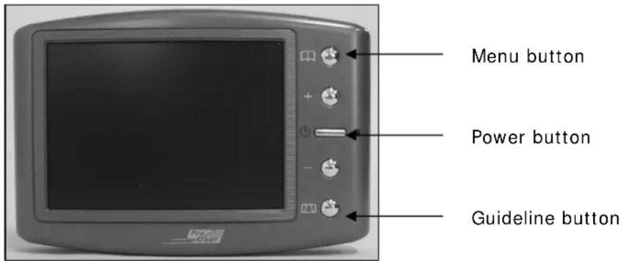
Power button
Press the POWER button to supply power to the monitor. When the monitor image is on, the blue LED will be lit. If there is power to the monitor, but the monitor image is OFF, the blue LED will blink on and off. When the monitor power is off, no picture can appear on the screen and the blue LED will be off.
Menu button
Press the Menu button to enter the menu screen as shown below:
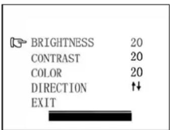
Repeat pressing the Menu button to select Brightness, contrast, colour or direction of the picture.
Press the + button or - button to adjust settings within the control selected. Press the + button to increase the value and press the - button to decrease the value.
To change the orientation of the screen image, press the menu button until direction is selected. By pressing the + or - button repeatedly, different screen orientations will be


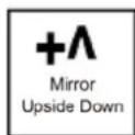
available. These different views allow you to mount the camera and monitor in any position with keeping the right picture on the monitor.
To exit the menu screen, select exit on the screen.
Guideline button
This camera system has the option to show distance-guidelines on the display. This helps you to visually see the distance between the objects behind your car. By pressing the guideline button, you can switch this option on and off.
Channel switch buttons
When menu is not activated, press + or - buttons to switch from one channel to another channel, so you can choose to see the image from the rear of the vehicle or from the rear of your trailer.
TECHNICAL SPECIFICATIONS
| Camera | |
| Operating Voltage 12V DC | |
| Current consumption <150mA | |
| Image sensor CMOS | |
| No. of pixel 640x480 | |
| Resolution | >330 |
| Optical lens 2,4mm / F2,1 | |
| Wireless transmitter | |
| Transmission frequency 2414MHz,2468MHz | |
| RF transmission distance (open space) >80M | |
| LCD monitor | |
| Operation Voltage 12V DC | |
| Standby Current <45mA | |
| Operation Current <300mA | |
| LCD display screen size 3,5inch | |
| No. of pixel 320x240 | |
| Operation temperature -10 to +45 degree Celsius | |

E8 R&TTE 0208104 approved
ENVIRONMENTAL PROTECTION

Waste electrical products should not be disposed of with household waste. Please recycle where facilities exist. Check with your local authority or retailer for recycling advice.
WARRANTY
Pro-User warrants this product for a period of 2 years from the date of purchase to the original purchaser. Warranty is not transferable. Warranty covers defect against workmanship and materials only. To obtain warranty service, please return the unit to the place of purchase or authorized Pro-User dealer together with your proof of purchase. The warranty is void if the product has been damaged or not used as described in this manual. Warranty is void if a non-authorized repair has been performed. Pro-User makes no other warranty expressed or implied. Pro-User is only responsible for repair or replacement (at Pro-Users' Discretion) of the defective product and is not responsible for any consequential damage or inconvenience caused by the defect.
EINLEITUNG
The monitor will automatically turn on when the vehicle is in reverse gear.
There are 5 control buttons available for users to have their controls:
Bouton menu
Bouton Marche / Arret
Bouton grille de distance
Bouton POWER (M/A)
Declaration of Conformity
Application of Council Directives
CE-R&TTE, CE-LVD
Standards to which Conformity are Declared:
A) CE-R&TTE
EN301489-1 V1.8.1:2008
EN301489-3 V1.4.1:2002
EN300440-2 V1.2.1:2008
EN300440-1 V1.4.1:2008
B) CE-LVD
EN 60950-1: 2006
Manufacturer's Name: Pro User International Ltd.
Manufacturer's Address: Unit 2504, 25/F, Nanyang Plaza, 57 Hung To Road, Kwun Tong, Kowloon, Hong Kong
Type of Equipment: Wireless Back-up Camera System
Model No.:RVC3620N
We, Pro User International Ltd, hereby declare that the equipment specified above conforms to the above Standards.
Place: Hong Kong
Date: 27 Apr, 2010

Unit 2504, 25/F, Nanyang Plaza, 57 Hung To Road, Kwun Tong, Hong Kong
57 2504
info@pro-user.com
www.pro-user.com
www.pro-user.com
Pro
User