
RTI 102 E - Thermostat AEG - Free user manual and instructions
Find the device manual for free RTI 102 E AEG in PDF.
| Product type | Electronic room thermostat |
| Model | RTI 102 E |
| Brand | AEG |
| Power supply | 230 V ~ 50 Hz, 1/N/PE |
| Switching capacity | 10 A |
| Temperature setting range | 5 °C to 35 °C (center position ~20 °C) |
| Operation | On/Off regulation of the heat accumulator fans |
| Control type | 2 positions: fans at full speed or stop |
| Temperature sensor | Built-in (room sensor) |
| Display | None (adjustment via potentiometer and switch) |
| Dimensions (approx.) | Approximately 80 x 80 x 30 mm |
| Mounting | Built into the heat accumulator (right side panel) |
| Protection | Fuse 250 V 2 A time-lag (in the accumulator) |
| Compatibility | AEG heat accumulators series WSP 1210 F to 4810 F, WSP 3510 N and 5010 N |
| Supplied accessories | On/Off switch, potentiometer, connection cable, 6-pole connector, stickers, instructions |
| Maintenance | No specific maintenance; clean with a dry cloth |
| Safety | Disconnect power before any intervention; comply with VDE 0100 standard |
| Repairability | Spare parts available; repair by an authorized specialist |
| Warranty | Valid in the country of purchase, subject to installation by a professional |
Frequently Asked Questions - RTI 102 E AEG
User questions about RTI 102 E AEG
0 question about this device. Answer the ones you know or ask your own.
Ask a new question about this device
Download the instructions for your Thermostat in PDF format for free! Find your manual RTI 102 E - AEG and take your electronic device back in hand. On this page are published all the documents necessary for the use of your device. RTI 102 E by AEG.
USER MANUAL RTI 102 E AEG
RTi 102 E, RTi 103 EP
Deutsch
Integrated Room Temperature Regulator
for Electric Storage Heaters
WSP 1210 F to WSP 4810 F,
WSP 3510 N and WSP 5010 N
Operating and Installation instructions
RTi 102 E, RTi 103 EP
François
1. Operating instructions
For the user
1.1 Functional principle 12
2. Installation instructions
For the fitter
2.1 Technical data 13
2.2 Packing unit 13
2.3 Installation 13
2.4 Function test 15
2.5 Transfer 15
3.Environment and recycling 18
1. Operating Instructions
RTi 102 E
The room temperature regulator RTi 102 E is an electronic 2-position controller, i.e. the fans of the storage heater are switched on, operated at constant speed and switched off again.
RTi 103 EP
The room temperature regulator RTi 103 EP is an electronic proportional controller, i.e. the speed of the storage heater's fan motors is adapted to the heat requirement continuously by the RTi 103 EP.
The speed of the fan motors is controlled dependent on the difference between the room temperature (actual temperature) and the temperature (nominal temperature) set at the selector button. The smaller this difference, the lower the speed of the fan motors.
If, however, the storage heater is operated with a supplementary heater, the RTi 103 EP automatically switches to a 2-position control when switching on the supplementary heater (B), if heat is discharged the fan motors only run at full power.
If the supplementary heater (B) is switched off by the switch in the control panel, the RTi 103 EP is operating as a proportional controller again.
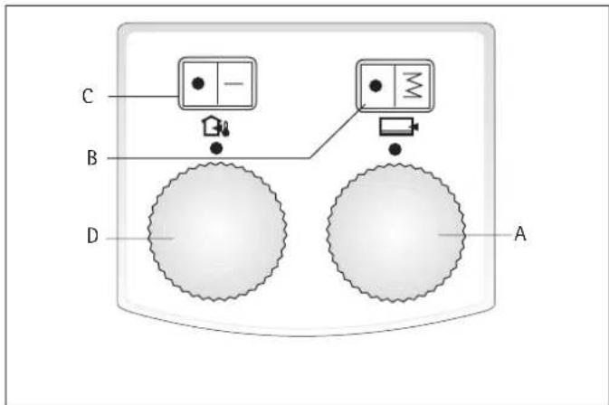
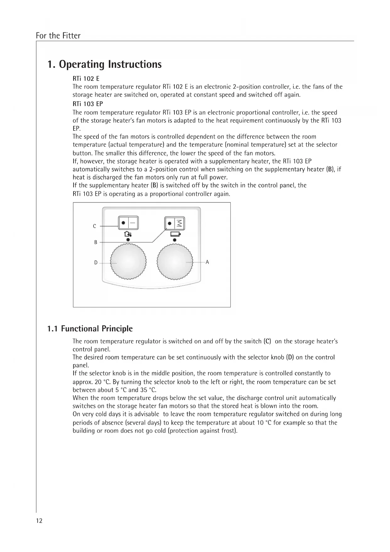
1.1 Functional Principle
The room temperature regulator is switched on and off by the switch (C) on the storage heater's control panel.
The desired room temperature can be set continuously with the selector knob (D) on the control panel.
If the selector knob is in the middle position, the room temperature is controlled constantly to approx. 20^ . By turning the selector knob to the left or right, the room temperature can be set between about 5^ and 35^ .
When the room temperature drops below the set value, the discharge control unit automatically switches on the storage heater fan motors so that the stored heat is blown into the room.
On very cold days it is advisable to leave the room temperature regulator switched on during long periods of absence (several days) to keep the temperature at about 10^ for example so that the building or room does not go cold (protection against frost).
2. Installation instructions

The room temperature regulator must be fitted by an authorised specialist under consideration of these operation and installation instructions and the operating and installation instructions of the storage heater.
All electrical connection and installation work must be performed in accordance with the VDE regulations 0100, the regulations of the electricity supply company responsible and the pertinent national and regional regulations.
2.1 Technical Data
| Model | RTi 102 E | RTi 103 EP |
| Rated voltage | 1/N/PE ~ 50 Hz 230 V | 1/N/PE ~ 50 Hz 230 V |
| Connection rating | 10 A | 10 A with supplementary heating |
| Control power | - | 100 VA |
2.2 Packing Unit
1 room temperature regulator with
- connecting lead charging and discharge control unit
- 6-pole connector with cable harness
1 ON/OFF switch switch with 2 wires
1 potentiometer with connecting lead
1 temperature selector knob
1 Operating and installation instructions
1 room temperature sensor with 2 screws
1 circuit diagram label
1 control panel label
2.3 Installation
Disconnect the storage heater from the power supply before starting installation work.
When connecting the storage heater to an automatic charging control unit, there may be voltage at the terminals A1/Z1 - A2/Z2 even when the fuses are removed.
When installing several storage heaters in a row make sure that the room temperature controller is installed in the outside right unit. This guarantees that the room temperature can be measured properly.
2.3.1 Order of Installation
- Remove air outlet and inlet grille, front wall and right side wall as described in the storage heater operation and installation instructions;
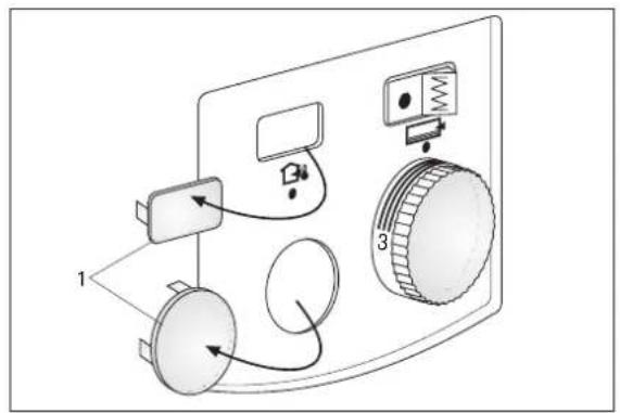
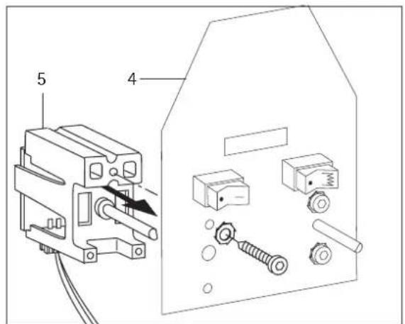
- Press the dummy caps (1) for the switch and temperature selector knob out of the control panel at the top and bottom left from the switching area side using a suitable tool.
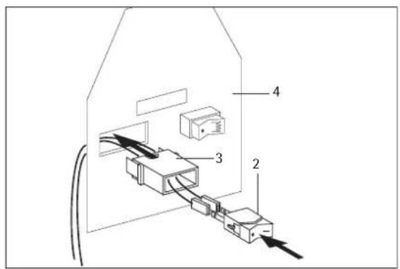
- Installation of the ON/OFF switch:
Push the black wire (length L = 550 mm ) and brown wire with the flat connectors onto the switch (2) through the holder (3) and snap the holder onto the metal bracket (4).
Press the On/Off switch (2) with the symbol "I" into the right of the holder.
Fix the potentiometer (5) with plugged on 3-wire connecting lead from the switching area side to the angle plate (4) with a screw 4 × 10 ~mm . It should be noted here that the rotary axis of the potentiometer is turned to the left (anti-clockwise) and the flat side of the rotary axis is facing to the right.
- Lay the 3-wire connecting lead of the potentiometer along the back of the angle plate to the discharge control unit slot (fix the connecting lead to the control panel and the angle plate with the cable strap).
- Swing forward the angle plate in the switching area to take up the mains terminals after loosening (not completely unscrewing) the screw in the rear wall.
- Plug the connecting lead (X25) on the discharge control unit (A2) to the charging control unit (A1) (page 7).
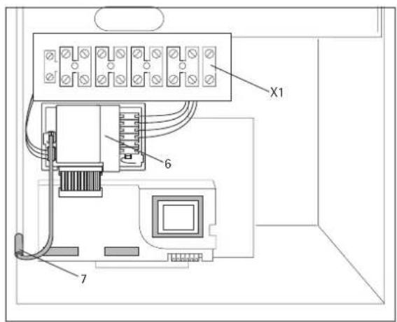
- Feed the 6-pole connector of the discharge control unit (A2 see circuit diagram) up along the back of the angle plate into the slots "TA" to "N" of the terminal block X2 from above and screw (press cable harness into the existing cable straps).
- Plug and snap in the discharge control unit (6) in the elongated holes above the charging control unit.
- Plug the connecting lead of the potentiometer into the slot X21 of the room temperature regulator.
- Screw the room temperature sensor (7/B2) with 2 screws (2.9 × 6.5) to the front edge of the floor plate. Plug the connecting cable to slot X20 of the room temperature regulator.
- Lay the enclosed separate wires along the back of the angle plate and connect according to the following table (to the terminals X1 and X2 from below).
| Designation | laying | |
| of | to | |
| wire (black) | L (X1) | S2 (slot top) |
| wire (brown) | LE' (X2) | S2 (slot bottom) |
Wires may not touch the control panel circuit board and singly insulated wires for safety low voltage!
Tie the wires to the switch in the existing cable harness (cable straps can be opened and reclosed).
- Swing back the angle plate and screw tight.
- Stick the control panel label to the outside of the right side wall.
Fix the side wall, front wall and air outlet and inlet grille back to the unit (in the right order!).
The toothed washers must be inserted under the fastening screws (protective earth connection!)
The connecting lead from the control panel to the room temperature regulator must be laid and secured in the same way as the existing leads to the control panel. They may not touch the intermediate wall and the heating element connections.

2.4 Function Test
Move the ON/OFF switch to the discharge position
Turn the temperature selector knob until the fan in the storage heater unit switches on.
If the fan does not switch on, the operating and fault indicators on the charging and discharge control unit must be observed.
2.4.1 Operating and fault indicators on the charging control unit
LED lights "green" no fault The charging control unit is working perfectly.
LED lights "red" Fault
a) Selector knob for charging (R1) and/or brick sensor (B1) defective or not connected.
b) Plug-in bridge for reduction of charging factor on the charging control unit. No charging takes place.
LED lights "orange" Fault on the discharge control unit
a) Discharge control unit defective
b) Potentiometer for setting the discharge defective and/or not connected. The room temperature is controlled at approx. 22^
c) Room temperature sensor defective and/or not connected. No discharging takes place.
2.5 Transfer
These operating and installation instructions are part of the unit and must be kept in a safe place by the user. In the case of a change of ownership they must be handed over to the new owner. The specialist must be given access to the operating and installation instructions for any repair work.
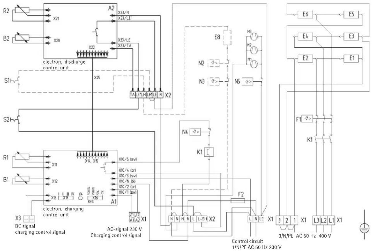
Circuit diagram WSP 1210 - 4810 F with RTi 102 E Circuit diagram WSP 3510 and 5010 N with RTi 102 E
A1: Electronic charging control unit
B1: Brick temperature sensor - charging
E1 - E6: Heating element (storage heater)
F1: Safety temperature limiter
F2: Fuse (250 V/2 A slow-blow)
K1: Thermal relay
M1 - M3: Fan discharge
N4: Temperature limiter - charging
N5: Temperature limiter - discharging
R1: Adjuster - charging (selector knob)
V4: Pilot lamp operation emergency operation
X1: Mains terminal
X2: Terminal
X3: DC terminal 0.91 - 1.43 V
X16: Control signal matching 4-stage
X17: Power reducer 4-stage
Special accessories
not included in delivery scope, mark the respective accessory if installed
Integr. room temperature regulator 2-position
A2: Electronic discharge control unit
B2: Room temperature sensor discharge
R2: Adjuster discharge (selector knob)
S2: ON/OFF switch room temperature regulator
Supplementary heater
E8: Supplementary heating element
N2: Temperature regulator - supplementary heater
N3: Temperature regulator - supplementary heater
S1: ON/OFF switch - supplementary heater
Note the permissible rating of the room temperature regulator when installing the supplementary heater (E8).
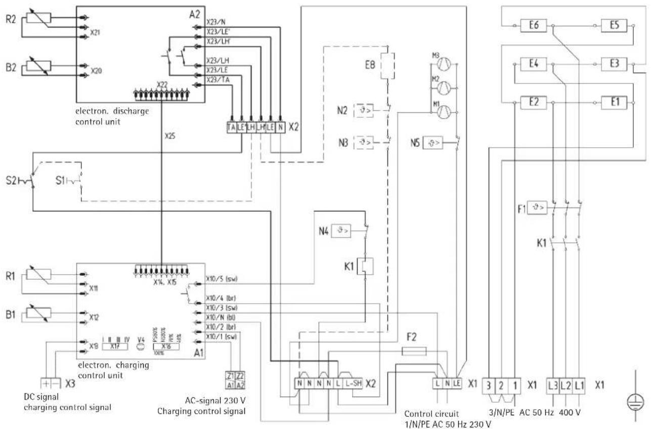
Circuit diagram WSP 1210 - 4810 F with RTi 103 EP Circuit diagram WSP 3510 and 5010 N with RTi 103 EP
A1: Electronic charging control unit
B1: Brick temperature sensor - charging
E1 - E6: Heating element (storage heater)
F1: Safety temperature limiter
F2: Fuse (250 V / 2 A slow-blow)
K1: Thermal relay
M1 - M3: Fan discharge
N4: Temperature limiter - charging
N5: Temperature limiter - discharging
R1: Adjuster - charging (selector knob)
V4: Pilot lamp operation emergency operation
X1: Mains terminal
X2: Terminal
X3: DC terminal 0.91 - 1.43 V
X16: Control signal matching 4-stage
X17: Power reducer 4-stage
Special accessories
not included in delivery scope, mark the respective accessory if installed
Integr. room temperature regulator proportional
A2: Electronic discharge control unit
B2: Room temperature sensor discharge
R2: Adjuster discharge (selector knob)
S2: ON/OFF switch room temperature regulator
Supplementary heater
E8: Supplementary heating element
N2: Temperature regulator - supplementary heater
N3: Temperature regulator - supplementary heater
S1: ON/OFF switch - supplementary heater
Note the permissible rating of the room temperature regulator when installing the supplementary heater (E8)!
3 Guarantee

For guarantee please refer to the respective terms and conditions of supply for your country.
The installation, electrical connection and first operation of this appliance should be carried out by a qualified installer.
The company does not accept liability for failure of any goods supplied which are not installed in accordance with the manufacturer's instructions.
3.1 Environment and recycling
Please help us to protect the environment by disposing of the packaging in accordance with the national regulations for waste processing.
Disposal of shipping packaging and scrapped units
Scrapped units must be disposed of professionally and properly according to locally applicable laws and regulations. They must be collected separately and disposed off according to local regulations.
Sommaire
AEG Home Comfort Czech
K Hajum 946


- RTi 102 E, RTi 103 EP
- Operating instructions
- Installation instructions
- RTi 102 E
- RTi 103 EP
- Functional Principle
- Technical Data
- Packing Unit
- Installation
- Order of Installation
- Function Test
- Operating and fault indicators on the charging control unit
- Transfer
- Circuit diagram WSP 1210 - 4810 F with RTi 102 E Circuit diagram WSP 3510 and 5010 N with RTi 102 E
- Special accessories
- Circuit diagram WSP 1210 - 4810 F with RTi 103 EP Circuit diagram WSP 3510 and 5010 N with RTi 103 EP
- Guarantee
- Environment and recycling
- Sommaire
Brand : AEG
Model : RTI 102 E
Category : Thermostat