
RTI 101 EP - Thermostat AEG - Free user manual and instructions
Find the device manual for free RTI 101 EP AEG in PDF.
| Product type | Integrated room thermostat for thermal storage heaters |
| Brand | AEG |
| Model | RTI 101 EP |
| Nominal voltage | 1/N/PE ~ 50 Hz 230 V |
| Breaking capacity | 16 A (with auxiliary heating) |
| Fan control power | 100 VA |
| Temperature setting range | Approximately 5 °C to 35 °C |
| Control mode | Proportional (continuous) / 2-point (with auxiliary heating) |
| Compatibility | Thermal storage heaters WSP 2010 to WSP 7010 |
| Accessories included | Thermostat, spacer supports, controller with cable, 6-pole connector, switch, selector, instructions, stickers, cable holders, torsion clamps |
| Installation | By a qualified specialist, in accordance with VDE 0100 regulations |
| Maintenance and cleaning | External cleaning with a dry, non-abrasive cloth. No internal parts to maintain. |
| Safety | Disconnect the power supply before any intervention. The device may still be energized even after removing the fuses (load management module). |
| Spare parts and repairability | Contact AEG after-sales service for spare parts. Any repair must be carried out by a qualified professional. |
| Warranty | To be claimed in the country of purchase from AEG Home Comfort or the authorized importer. |
| Environment and recycling | Dispose of packaging according to national regulations. The appliance at end of life must be recycled in accordance with applicable regulations. |
Frequently Asked Questions - RTI 101 EP AEG
User questions about RTI 101 EP AEG
0 question about this device. Answer the ones you know or ask your own.
Ask a new question about this device
Download the instructions for your Thermostat in PDF format for free! Find your manual RTI 101 EP - AEG and take your electronic device back in hand. On this page are published all the documents necessary for the use of your device. RTI 101 EP by AEG.
USER MANUAL RTI 101 EP AEG
Integrated Room Temperature Regulator
for Electric Storage Heaters
WSP 2010 to WSP 7010
Operating and Installation instructions
RTi 101 EP
Français
1. Operating instructions For the user
1.1 Functional principle 10
2. Installation instructions
For the fitter
2.1 Technical data 11
2.2 Packing unit.... 11
2.3 Installation 11
2.4 Function test 13
2.5 Transfer.... 13
3. Environment and recycling 15
Sommaire
Français Nederlands
Inhoudsopgave
natural_image
Pure electrical circuit lines without any symbols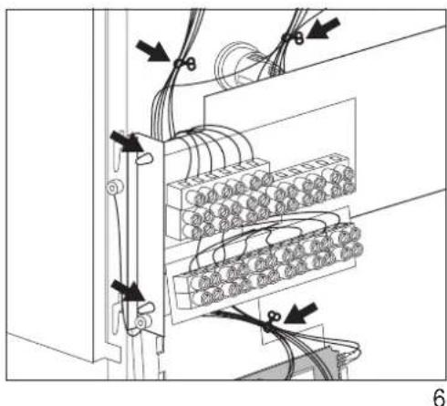
natural_image
Electrical wiring diagram showing connections between a panel with connectors and cables (no text or symbols)1. Operating Instructions
RTi 101 EP
The room temperature regulator RTi 101 EP is an electronic proportional controller, i.e. the speed of the storage heater's fan motors is adapted to the heat requirement continuously by the RTi 101 EP.
The speed of the fan motors is controlled dependent on the difference between the room temperature (actual temperature) and the temperature (nominal temperature) set at the selector button. The smaller this difference, the lower the speed of the fan motors.
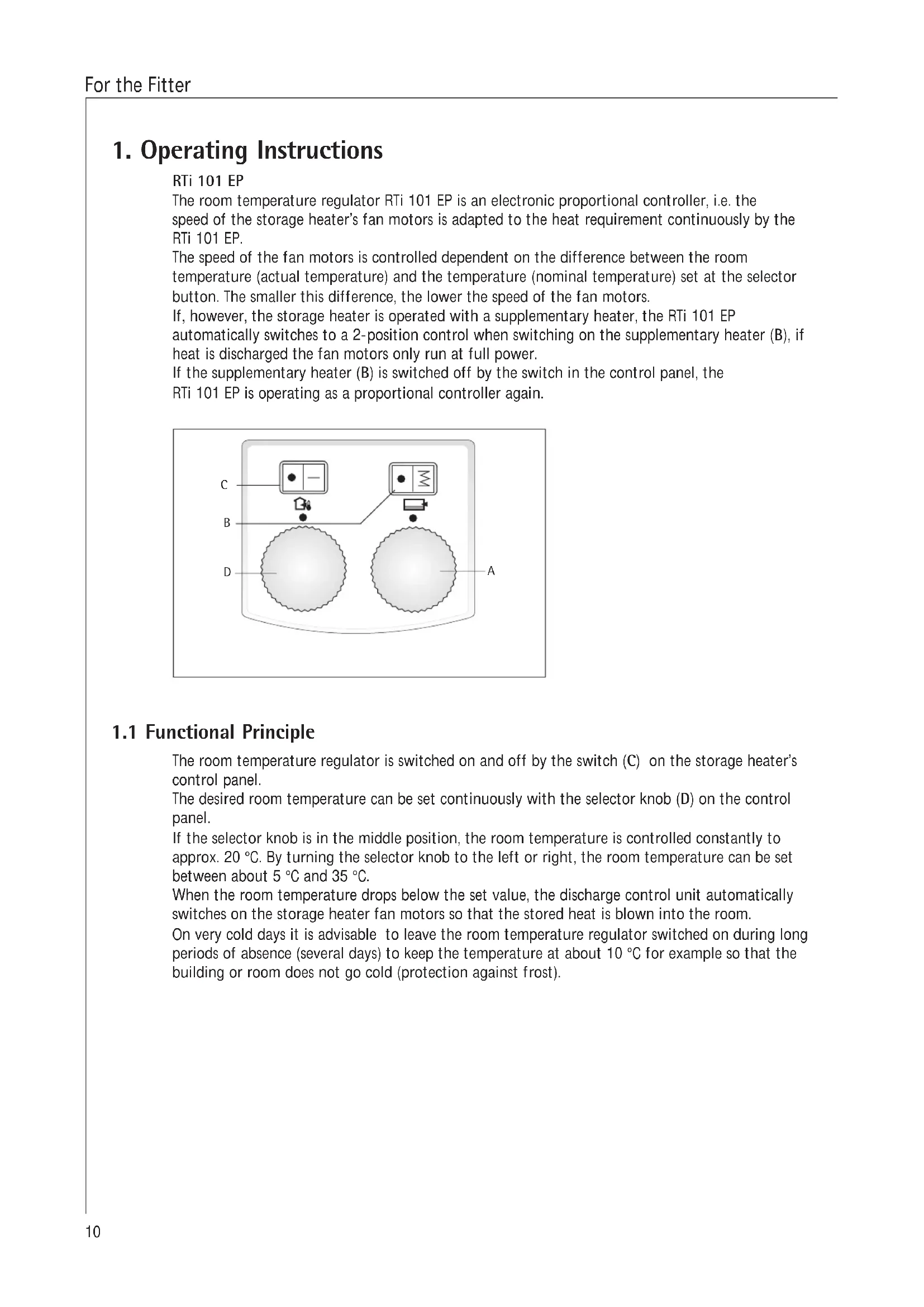
If, however, the storage heater is operated with a supplementary heater, the RTi 101 EP automatically switches to a 2-position control when switching on the supplementary heater (B), if heat is discharged the fan motors only run at full power.
If the supplementary heater (B) is switched off by the switch in the control panel, the RTi 101 EP is operating as a proportional controller again.
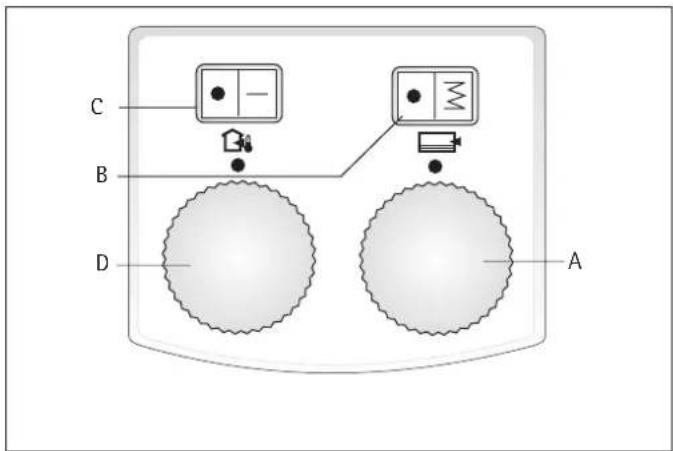
1.1 Functional Principle
The room temperature regulator is switched on and off by the switch (C) on the storage heater's control panel.
The desired room temperature can be set continuously with the selector knob (D) on the control panel.
If the selector knob is in the middle position, the room temperature is controlled constantly to approx. 20 °C. By turning the selector knob to the left or right, the room temperature can be set between about 5 °C and 35 °C.
When the room temperature drops below the set value, the discharge control unit automatically switches on the storage heater fan motors so that the stored heat is blown into the room.
On very cold days it is advisable to leave the room temperature regulator switched on during long periods of absence (several days) to keep the temperature at about 10 °C for example so that the building or room does not go cold (protection against frost).
2. Installation instructions

The room temperature regulator must be fitted by an authorised specialist under consideration of these operation and installation instructions and the operating and installation instructions of the storage heater.
All electrical connection and installation work must be performed in accordance with the VDE regulations 0100, the regulations of the electricity supply company responsible and the pertinent national and regional regulations.
2.1 Technical Data
| Model | RTi 101 EP |
| Rated voltage | 1/N/PE ~ 50 Hz 230 V |
| Connection rating | 16 A with supplementary heater |
| Control rating fan | 100 VA |
2.2 Packing Unit
1 Room temperature regulator with four spacers and
- potentiometer with connecting lead
- 6-pole connector with cable harness
1 ON/OFF switch with 2 wires (length 500 mm)
1 temperature selector knob
1 Operating and installation instructions
1 separate double wire (length 500/650 mm)*
1 separate wire with distributor (length 150 mm)*
1 circuit diagram label
1 control panel label
2 cable straps
2 cable twisters
* only needed in connection with ZH 1004 to ZH 1017
2.3 Installation

Disconnect the storage heater from the power supply before starting installation work.
When connecting the storage heater to an automatic charging control unit, there may be voltage at the terminals A1/Z1 - A2/Z2 even when the fuses are removed.
When installing several storage heaters in a row make sure that the room temperature controller is installed in the outside right unit. This guarantees that the room temperature can be measured properly.
2.3.1 Order of Installation
- Remove air outlet and inlet grille, front wall and right side wall as described in the storage heater operation and installation instructions;
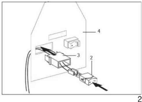
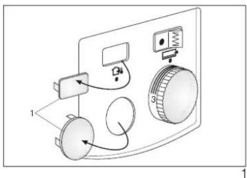
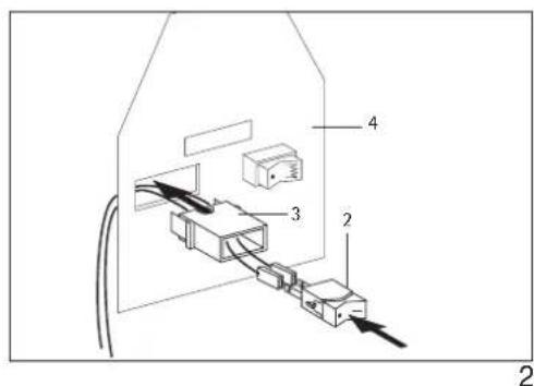
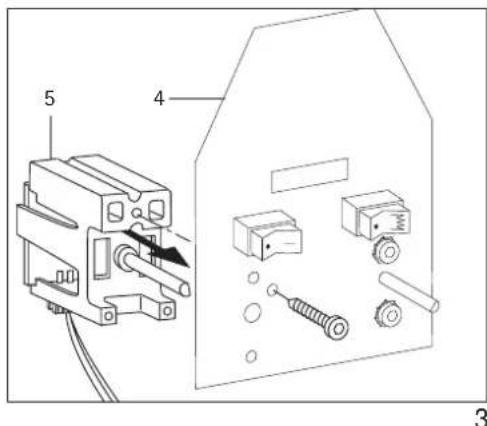
- Press the dummy caps (1) for the switch and temperature selector knob out of the control panel at the top and bottom left from the switching area side using a suitable tool (fig. 1).
• Installation of the ON/OFF switch:
Push both wires through the cut-out in the metal bracket and snap onto the metal bracket (4) with the holder (fig. 2).
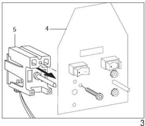
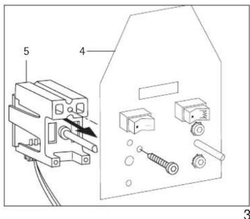
Press the on/off switch (2) into the holder with the symbol "I" at the right. Push the wires through the long, oval opening of the angle plate on which the socket strip is mounted from rear to front and clamp the wires arranged at the centre of the switch to the top terminal strip X2 (LE') and the outside wire to the bottom terminal strip X1 (L) (see page 15 in the circuit diagram). - Fix the potentiometer (5) with plugged on 3-wire connecting lead from the switching area side to the angle plate (4) with a screw 4 × 10 ~mm . It should be noted here that the rotary axis of the potentiometer is turned to the left (anti-clockwise) and the flat side of the rotary axis is facing to the right (fig. 3).
-
Lay the 3-wire connecting lead of the potentiometer along the back of the angle plate to the discharge control unit slot. To do this, pull off the 3-pin plug from the potentiometer, lay the cable and replace the 3-pin plug.
-
Swing forward the angle plate in the switching area to take up the mains terminals after loosening (not completely unscrewing) the screw in the rear wall.
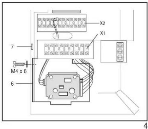
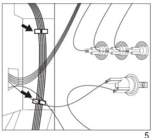
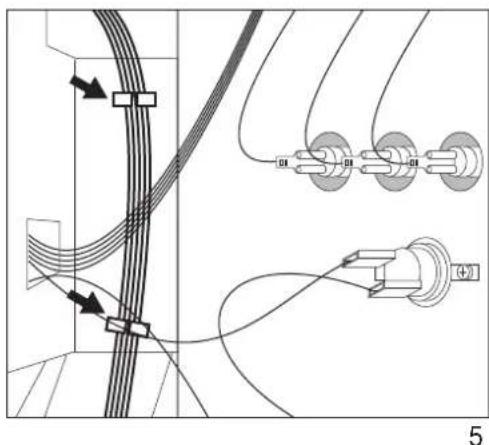
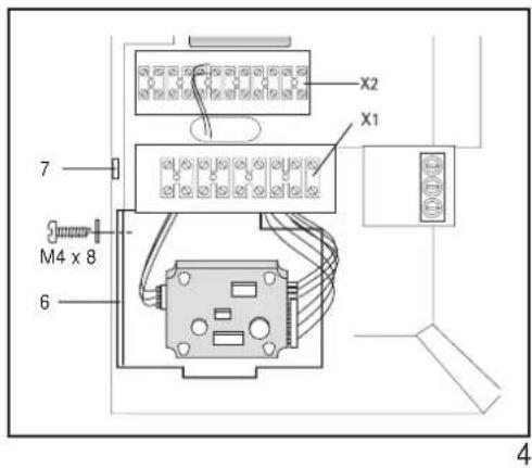
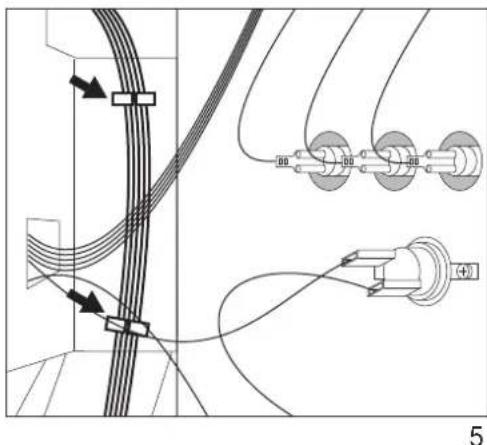
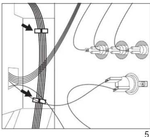
- Insert the cable holders provided in the prepared holes in the angle plate (fig. 6) and fix the wires in the cable holders as shown in figure 5.
The enclosed cable twisters are used for additional fixing of the cable from the potentiometer (5) and the 6-wire supply cable to the board as shown in figure 6. - Feed the 6-pole connector of the discharge control unit (A3 see circuit diagram) up along the back of the angle plate into the slots „TA“ to „N“ of the terminal block X2 from above and screw (press cable harness into the existing cable straps).
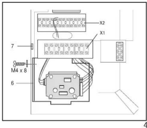
The cables may not touch the intermediate wall and the heating element connections. - Attach the preassembled unit consisting of controller and support plate (6) to the upper sheet-metal bracket of the control panel (support plate of terminal strips X1 and X2). To do so, engage the lower sheet-metal bracket behind the locking tab of the upper sheet-metal bracket (7). The two brackets are joined together by means of a screw (M4x8) (Fig. 4).
| Designation | Laying only in connection with ZH | |
| of | according to | |
| double wire (black) | S1 | A3 LH and X2 LH |
| wire with distributor (black) | S1 | S2 |

natural_image
Pure electrical circuit lines without any symbols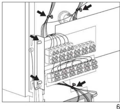
natural_image
Electrical wiring diagram showing connections between a server rack and cable ports (no text or symbols)- The separately included wires (double wire and switching wire with distributor) are only needed in connection with ZH 1004 to ZH 1017. Switch S1 is included with the ZH kits. Please observe the Instructions for Use and Assembly for Additional Heaters ZH 1004 to 1017.
Tie the wires to the switch in the existing cable harness (cable straps can be opened and reclosed).
- Swing back the angle plate and screw tight.
- Stick the control panel label to the outside of the right side wall.
- Fix the side wall, front wall and air outlet and inlet grille back to the unit (in the right order!).
The toothed washers must be inserted under the fastening screws (protective earth connection!)
- Plug on the temperature selector knobs.
2.4 Function Test
Move the ON/OFF switch to the discharge position
Turn the temperature selector knob until the fan in the storage heater unit switches on. If the fan does not switch on, the operating and fault indicators on the charging and discharge control unit must be observed.
2.5 Transfer
These operating and installation instructions are part of the unit and must be kept in a safe place by the user. In the case of a change of ownership they must be handed over to the new owner. The specialist must be given access to the operating and installation instructions for any repair work.
Circuit diagram WSP 2010 - 7010 with RTi 101 EP
E1 - E6: Heating element (storage heater)
E7: Heating resistor
F1: Safety temperature limiter
M1 - M3: Fan
N1: Temperature limiter - charging
N5: Temperature limiter – fan drawer
N4: Temperature limiter - charging
X1: Mains terminal
X2: Terminal
Integr. Room temperature regulator RTi 101 EP
R2: Adjuster discharge (selector knob)
S2: Rocker switch - discharging
□ Supplementary heater
E8: Supplementary heating element
N2: Temperature regulator – supplementary heater
N3: Temperature regulator – supplementary heater
S1: Rocker switch – supplementary heater
![A3 x = wiring harness P1 P2 P3 ZH TA N LE L LH LH bk, approx. 400 lg N2 [→] N3 [→] R2 bk, approx. 500 lg bk, approx. 650 lg bk, approx. 500 lg TA LE LH LH LE N X2 S1 bk, approx. 150 lg S2 bk, approx. 500 lg bk, approx. 500 lg bl, approx. 230 lg N N N N L L-SH X2 L N LE X1 AC-signal 230 V Charging control signal Control circuit 1/N/PE ~ 50 Hz 230 V 3/N/PE ~ 50 Hz 400 V E8 M3 M2 M1 N5 -9> E6 E5 E4 E3 E2 E1 N4 -9> N1 -9> F1 -9> X1 L3 L2 L1 X1 Z1 Z2 A1 A2](/content/2026/02/373371/images/e0730ebd0627eabebceac07c2bcc5b8a4f338eb669c6b151e2526b5d59981782.jpg)
3. Environment and recycling
Please help us to protect the environment by disposing of the packaging in accordance with the national regulations for waste processing.
Guarantee
For guarantee please refer to the respective terms and conditions of supply for your country.
The installation, electrical connection and first operation of this appliance should be carried out by a qualified installer.
The company does not accept liability for failure of any goods supplied which are not installed in accordance with the manufacturer's instructions.


natural_image
Pure electrical circuit lines without any symbols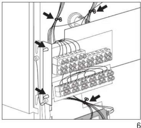
natural_image
Electrical wiring diagram showing connections between a server rack and cable bundles (no text or symbols)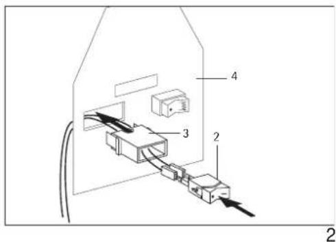
natural_image
Pure electrical circuit lines without any symbols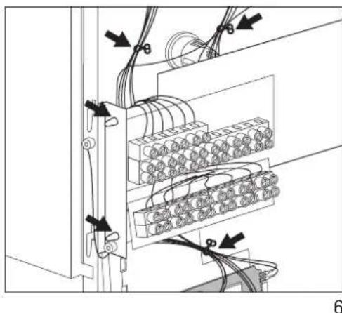
natural_image
Electrical wiring diagram showing connections between two server racks with cable routing (no text or symbols)

- RTi 101 EP
- Operating instructions For the user
- Installation instructions
- Environment and recycling 15
- Sommaire
- Inhoudsopgave
- Operating Instructions
- Functional Principle
- Technical Data
- Packing Unit
- Installation
- Order of Installation
- Function Test
- Transfer
- Circuit diagram WSP 2010 - 7010 with RTi 101 EP
- Environment and recycling
- Guarantee
Brand : AEG
Model : RTI 101 EP
Category : Thermostat