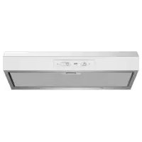
CWB 6930 X - Basket BEKO - Free user manual and instructions
Find the device manual for free CWB 6930 X BEKO in PDF.
Download the instructions for your Basket in PDF format for free! Find your manual CWB 6930 X - BEKO and take your electronic device back in hand. On this page are published all the documents necessary for the use of your device. CWB 6930 X by BEKO.
USER MANUAL CWB 6930 X BEKO
- Commandes(Fig.18)Mécaniqueslessymbolessontles suivants: A = touche ECLAIRAGE B = touche OFF C = touche PREMIERE VITESSE D = touche DEUXIEME VITESSE E = touche TROISIEME VITESSE. NOUS DECLINOS TOUTE RESPONSABILI TE POUR LES EVENTUELS DÉGATS PROVOQUÉS PAR L’INOBSERVATION DES SUSDITES INSTRUCTIONS. - 24 -GENERAL Carefully read the following important information regarding installation safety and maintenance. Keep this information booklet accessible for further consultations. The appliance has been designed for use in the ducting version (air exhaust to the outside – Fig.1B), ltering version (air circulation on the inside – Fig.1A) or with external motor (Fig.1C). SAFETY PRECAUTION
1. Take care when the cooker hood is operating simultane-
ously with an open replace or burner that depend on the air in the environment and are supplied by other than electrical energy, as the cooker hood removes the air from the environ- ment which a burner or replace need for combustion. The negative pressure in the environment must not exceed 4Pa (4x10⁻⁵ bar). Provide adequate ventilation in the environment for a safe operation of the cooker hood. Follow the local laws applicable for external air evacuation. Before connecting the model to the electricity network: - Control the data plate (positioned inside the appliance) to ascertain that the voltage and power correspond to the network and the socket is suitable. If in doubt ask a qualied electrician. - If the power supply cable is damaged, it must be replaced with another cable or a special assembly, which may be obtained direct from the manufacturer or from the Technical Assistance Centre. - This device must be connected to the supply network through either a plug fused 3A or hardwired to a 2 fase spur protected by 3A fuse.
In certain circumstances electrical appliances may be a danger hazard. A) Do not check the status of the lters while the cooker hood is operating. B) Do not touch bulbs or adjacent areas, during or straight after prolonged use of the lighting installation. C) Flambè cooking is prohibited underneath the cooker hood. D) Avoid free ame, as it is damaging for the lters and a re hazard. E) Constantly check food frying to avoid that the overheated oil may become a re hazard. F) Disconnect the electrical plug prior to any maintenance. G) This appliance is not intended for use by young children or inrm persons without supervision. H) Young children should be supervised to ensure they do not play with the appliance
I) There shall be adequate ventilation of the room when
the rangehood is used at the same time as appliances burning gas or other fuels. L) There is a risk of re if cleaning is not carried out in accordance with the instructions. This appliance conforms to the European Directive EC/2002/96, Waste Electrical and Electronic Equipment (WEEE). By making sure that this appliance is disposed of in a suitable manner, the user is helping to prevent potential damage to the environment or to public health. The symbol on the product or on the accompanying paperwork indicates that the appliance should not be treated as domestic waste, but should be delivered to a suitable electric and electronic appliance recycling collection point. Follow local guidelines when disposing of waste. For more information on the treatment, re-use and recycling of this product, please contact your local authority, domestic waste collection service or the shop where the appliance was purchased. INSTALLATION INSTRUCTIONS
- Assemblyandelectricalconnectionsmustbecarriedout by specialised personnel.
- Wear protective gloves before proceeding with the installation.
- ElectricConnection: Note! Verify the data label placed inside the appliance: - If the symbol appears on the plate, it means that no earth connection must be made on the appliance, therefore follow the instructions concerning insulation class II. - If the symbol DOES NOT appear on the plate, follow the instructions concerning insulation class I. Insulation class II - The appliance has been manufactured as a class II, therefore no earth cable is necessary. The plug must be easily accessible after the installation of the appliance. If the appliance is equipped with power cord without plug, a suitably dimensioned omnipolar switch with 3 mm minimum opening between contacts must be tted between the appliance and the electricity supply in compliance with the load and current regulations. - The connection to the mains is carried out as follows: BROWN = L line BLUE = N neutral. Insulation class I This is a class I, appliance and must therefore be connected to an eecient earthing system. - The appliance must be connected to the electricity supply as follows: BROWN = L line BLUE = N neutral YELLOW/GREEN = earth. The neutral wire must be connected to the terminal with the N symbol while the YELLOW/GREEN, wire must be connected to the terminal by the earth symbol
When connecting the appliance to the electricity supply, make sure that the mains socket has an earth connection. After tting the ducted cooker hood, make sure that the electrical plug is in a position where it can be accessed easily. If the appliance is connected directly to the electricity supply, an omnipolar switch with a minimum contact opening of 3 mm must be placed in between the two; its size must be suitable for the load required and it must comply with current legislation.
- The minimum distance between the support surfaces of the cooking pots on the cooker top and the lowest part of ENGLISH
- 25 -the cooker hood must be at least 45 cm. If a connection tube composed of two parts is used, the upper part must be placed outside the lower part. Do not connect the cooker hood ex- haust to the same conductor used to circulate hot air or for evacuating fumes from other appliances generated by other than an electrical source. Before proceeding with the assembly operations, remove the anti-grease lter(s) (Fig.2.2 - Fig.3.2) so that the unit is easier to handle. - In the case of assembly of the appliance in the suction version prepare the hole for evacuation of the air.
- We recommend the use of an air exhaust tube which has the same diameter as the air exhaust outlet hole. If a pipe with a smaller diameter is used, the eciency of the product may be reduced and its operation may become noisier.
- If the appliance is supplied with the small cupola M remove it by releasing it as indicated in Fig.2.3 - Fig.3.3. Before proceeding with the assembly operations, for easier manoeuvrability of the appliance disengage the anti-grease lter by pulling handle B as indicated in Fig.2.2 - Fig.3.2. If one owns a model with perimeter suction panel, before carrying out this operation, perform the following phases: - Open panel C as indicated in Fig.2.1 - Fig.3.1. - If one owns the version with three A panels release them from the xing pins by pulling outwards (Fig.3.4) and then remove them from safety pins N (Fig.3.4) placed inside the hood. To put them back perform the operation in reverse order. ATTENTION! During this disassembly and assembly operation ensure to hold the panel securely to prevent accidental falls.
- Wallmounting: Trace the bottom side of the hood on the wall. Consider the measurements shown in Fig.4A and minimum distance from the cooking surface (Fig.4B). - Position the xing template on the wall, making sure that the line coincides with the line previously made on the wall. - Mark the xing holes and cut them into the material (Fig.5). - Fix the 2 top screws K and screw anchors (Fig.5), without tightening them completely. - Position the appliance at the wall (Fig.6A). - Make sure the 2 levelling screws J are tightened (Fig.6B.1). - Align the appliance horizontally using the two levelling screws J (Fig.6B.1). - Once the adjustment has been made, fasten the hood permanently using the screws K (Fig.6C - Fig.6D). - For easy accessibility to the motor unit in the case of assistance, after having levelled and fixed the appliance denitively, we recommend that the brackets are removed (Fig.6B.1). - When carrying out the xing operations, use only screws and screw anchors suited to the type of wall (e.g. reinforced concrete, plasterboard etc.). - If the screws and screw anchors are supplied with the appliance, make sure that they are suited to the type of wall to which the hood must be xed.
- Installationofmodelswithoutdecorativeducts: Extractorhood - Unclip the canopy M and remove the grille E (Fig.7). - Pass the power supply cable through the slot in the canopy M, as indicated in Fig.9A.1. - Taking the grommet H, position it between the power cable and the slot (Fig.9A.2). - Connect the flexible hose L (not supplied) to the hood (Fig.9B). - Re-position the small cupola M paying attention that it is hitched perfectly to the xing pins G (Fig.9B).
- Filteringversion: - Unclip the canopy M and remove the grille E (Fig.7). - Pass the power supply cable through the slot in the canopy M, as indicated in Fig.8.1. - Taking the grommet H, position it between the power cable and the slot (Fig.8.2). - Fix the small cupola M and the grille E making sure that is it perfectly hooked on to the fastening pins G (Fig.8).
- Optionalaccessories: This model may have decorative ducts as optional accessories - ask your retailer for information. Before installing decorative ues it is necessary to remove the small cupola M and loosen the 4 screws Q that lock the fastening pins G as shown in Fig.11.
- Installationofmodelswithdecorativeducts: Extractorhood Make sure the electrical power supply is within the measurements of the decorative connector. Adjust the width of the support bracket of the top connector (Fig.10.2). Then x it to the ceiling so that it is on the same axis as the hood using screws A and observing the distance from the ceiling shown in Fig.10.1. Connect ange F to the air exhaust hole using exible hose L (Fig.12A). Slide the top connector inside the lower duct and place this on the body (Fig.12B). Pull out the top duct as far as the bracket and secure it using screws B (Fig.10.2). To transform the hood from a ducting version into a ltering version, ask your dealer for the charcoal lters and follow the installation instructions.
- Filterhood: Please note: The filters must be ordered from your dealer as an accessory. - To transform the hood from the SUCTION version to the FILTERING version, charcoal lters must be ordered from your dealer as an accessory. Two types of kit are available, one with non-renewable lters (Fig.13) and the other with renewable filters (washable) (Fig.14). Unlike traditional carbon lters, this carbon lter can be washed and reactivated for approximately 12-15 times. With normal hood use, this lter should be cleaned once every 2-3 months. The lter can be washed into a dishwasher at the highest temperature using a standard dishwasher detergent. After washing, dry the lter in the oven at 100° C for 10-15 minutes to reactivate it. The lter will retain its odour-absorbing capacity for three years, after which it will have to be replaced. - If a bracket is found in the packaging like that indicated in Fig.14 loosen the screws already installed inside the hood and install the bracket using the previously-removed screws. - To replace re-usable carbon filters Y, remove the brackets from their seat, pulling them outwards (Fig.14). - If your product is not supplied with the bracket, it means that the active charcoal lter cannot be renewed (Fig.13). These must be applied to the suction unit inside the hood, centring them in it and turning them 90° until they snap into place (Fig.13).
- 26 -USE AND MAINTENANCE
- We recommend that the cooker hood is switched on before any food is cooked. We also recommend that the appliance is left running for 15 minutes after the food is cooked, in order to thoroughly eliminate all contaminated air. The eective performance of the cooker hood depends on constant maintenance; the anti-grease lter and the active carbon lter both require special attention.
- Theanti-greaselter is responsible retaining the grease particles suspended in the air, therefore it is subject to clogging with variable frequency according to the use of the appliance. - To prevent the danger of possible res, at least every 2 months one must wash the anti-grease lters by hand using non-abrasive neutral liquid detergents or in the dishwasher at low temperatures and on short cycles. - After a few washes, colour alterations may occur. This does not give the right to claim their replacement.
- Theactivecarbonlters are used to purify the air that is sent back into the room and its function s to mitigate the unpleasant odours produced by cooking. - The non-regenerable active carbon lters must be replaced at least every 4 months. The saturation of the active charcoal depends on the more or less prolonged use of the appliance, on the type of kitchen and on the frequency with which anti- grease lter is cleaned. - Regenerable active charcoal lters must be washed by hand, with non abrasive neutral detergents, or in the dishwasher at a maximum temperature of 65°C (the washing cycle must be complete without dishware). Remove excess water without damaging the lter, remove the plastic parts, and let the mat dry in the oven for at least 15 minutes approximately at a maximum temperature of 100°C. To keep the regenerable charcoal lter functioning ecient this operation must be repeated every 2 months. These must be replaced at least every 3 years or when the mat is damaged.
- Beforeremountingtheanti-greaseltersandtherege- nerable active charcoal lters it is important that they are completely dry.
- Clean the hood frequently, both internally and externally, using a cloth dampened with denatured alcohol or neutral liquid detergents that are non abrasive.
- The lighting .system is designed for use during cooking and not for the prolonged general lighting of the room. The prolonged use of the lighting system signicantly decreases the average duration of the bulbs.
- If the appliance is equipped with courtesy lights it is possible to use them for general room lighting for a prolonged amount of time.
- Attention: The non compliance with the hood cleaning warnings and with the replacement and cleaning of the lters entails risk of res. One therefore recommends keeping to the suggested instructions.
- Replacinghalogenlightbulbs(Fig.15.1): To replace the halogen light bulbs B, remove the glass pane C using a lever action on the relevant cracks. Replace the bulbs with new ones of the same type. Caution: Do not touch the light bulb with bare hands.
- ReplacingLEDlamps(Fig.15.2): If the appliance version is with LED lamps, the intervention of a specialised technician is necessary to replace them.
- Commands Luminous(Fig.16) the key symbols are ex- plained below: A = LIGHT B = OFF
F = AUTOMATIC STOP TIMER - 15 minutes (*) If your appliance is equipped with the INTENSIVE speed function, start from level THREE speed and keeping the button E pressed for about 2 seconds, this function activates for about 10 minutes after which it goes back to the previously set speed. When the function is active the LED ashes. To interrupt it before the 10 minutes have expired press key E again. By pressing key F for two seconds (with the hood switched o) the “clean air” function is activated. This function switches the appliance on for ten minutes every hour at the rst speed. As soon as this function is activated the motor starts up at the rst speed for ten minutes, During this time key F and key C must ash at the same time. After ten minutes the motor switches o and the LED of key F remains switched on with a xed light until the motor starts up again at the rst speed after fty minutes and keys F and C start to ash again for ten minutes and so on. By pressing any key for the exclusion of the hood light the hood will return immediately to its normal functioning (e.g. if key D is pressed the “clean air” function is deactivated and the motor moves to the 2nd speed straight away. By pressing key B the function is deactivated). (*) The “AUTOMATIC STOP TIMER” delays stopping of the hood, which will continue functioning for 15 minutes at the operating speed set at the time this function is activated.
- Anti-grease/activecharcoallterssaturation: - When the A key ashes with a 2 second frequency the anti- grease lters must be washed. - When the A key ashes with a 0.5 second frequency the active carbon lters must be replaced or washed depending on the type of lter. Once the clean lter has been put back one must reset the electronic memory by pressing the A key for approximately 5 seconds until it stops ashing.
- Commands(Fig.17): Push-button A = On/O lights switch. Push-button B = Switches the motor on/O. The appliance switches on at speed level 1, If the cooker hood is on depress the push-button for 2 sec. to switch o the cooker hood. If the cooker hood is at speed level 1 it will not be necessary to depress the push-button to switch the cooker hood o. Decreases the motor speed. Display C = Indicates the motor speed level selected and activates the timer. Push-button D = Switches the motor on. Increases the motor speed. Touching the key at 3rd speed, the intensive function runs for 10’, then the appliance go back to work at the original speed. During this function the display blinks. Key E = The Timer times the functions on activation for 15 minutes, after which they are switched o. The Timer is deactivated by re-pressing Key E. When the Timer is activated the decimal point must ash on the display. The Timer cannot be activated if the intensive speed is functioning. - 27 -The “clean air” function is activated by pressing key E for 2 seconds when the appliance is switched o. This switches the motor on for 10 minutes every hour at the rst speed. During functioning a rotary movement of the peripheral segments must be visualised on the display. When this time has passed the motor switches o and the xed letter “C” must be visualised on the display until the motor re-starts after 50 minutes for another 10 minutes and so on. Press any key apart from the light keys to return to normal functioning. Press key E to deactivate the function.
- Activecarbon/greaseltersaturation: - When display item C ashes, at a speed where it alternates with the letter F (e.g. 1 and F), the grease lters must be washed. - When display item C ashes, at a speed where it alternates with the letter A (e.g. 1 and A), the active carbon lters must be replaced or washed depending on the type of lter. After the clean filter has been positioned correctly, the electronic memory must be reset by pressing button A for approximately 5 seconds, until the indication F or t shown on the display C stops ashing.
- Commands(Fig.18)Mechanical the keysymbolsare explainedbelow: A = LIGHT B = OFF