
PLM4628 - Lawn mower MAKITA - Free user manual and instructions
Find the device manual for free PLM4628 MAKITA in PDF.

User questions about PLM4628 MAKITA
0 question about this device. Answer the ones you know or ask your own.
Ask a new question about this device
Download the instructions for your Lawn mower in PDF format for free! Find your manual PLM4628 - MAKITA and take your electronic device back in hand. On this page are published all the documents necessary for the use of your device. PLM4628 by MAKITA.
USER MANUAL PLM4628 MAKITA
natural_image
Black-and-white photo of a Makit lawn mower with visible brand logo and model number (no text or symbols on the device itself)B PLM4626 C PLM4627

natural_image
Black-and-white photo of a Makitir lawn mower (no visible text or symbols on the device body)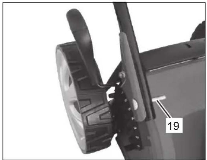
natural_image
Close-up of a mechanical component with visible parts and a numbered label (19), no readable text or symbols beyond the number.
natural_image
Close-up of a mechanical component with a circular head and attached lever, labeled '20' (no text or symbols on the object itself)1A 1B

natural_image
Close-up of a mechanical component with visible gears and adjustment knobs (no text or symbols)
natural_image
Close-up of a black industrial vehicle's wheel and lever assembly (no visible text or symbols)1C 1D

natural_image
Close-up of a black mechanical lever with attached bracket and adjustment knob (no text or symbols visible)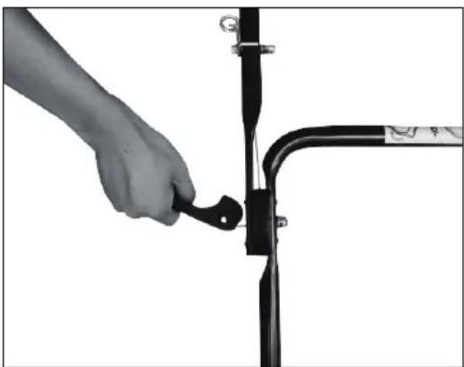
natural_image
Close-up of a hand adjusting a black metal bracket with a cable, against a plain background (no text or symbols visible)1E 1F
1G 1H
natural_image
Close-up of a black mechanical lever handle with adjustment knob and lever mechanism (no text or symbols visible)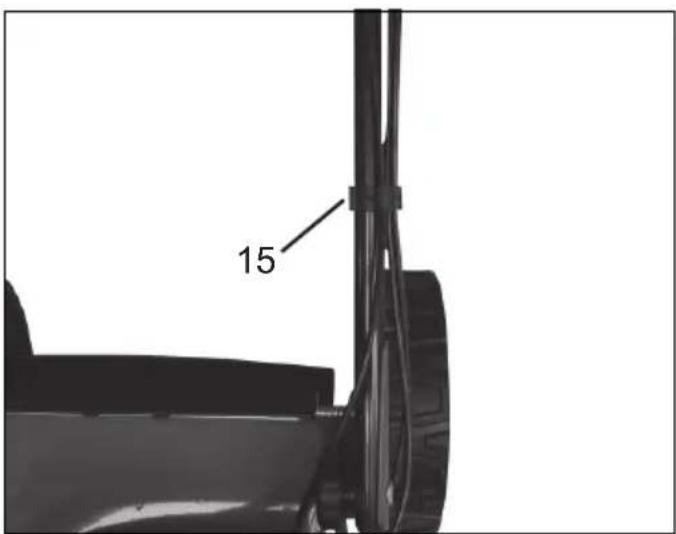

natural_image
Front view of a black wheeled cart with side legs and wheels (no visible text or symbols)11 1J
natural_image
Close-up of hands installing or adjusting a black mechanical component with visible wiring and a tire (no text or symbols)3A
2
natural_image
Black-and-white photo of a utility truck with overhead cable and roof structure (no visible text or symbols)3B 3C
natural_image
Close-up of a black industrial machine with attached cable and control panel (no visible text or symbols)
natural_image
Close-up of a black stroller with visible wheels and buttons (no text or symbols)5

natural_image
Side view of a black industrial machine with a lever and attached bracket (no visible text or symbols)4
natural_image
Close-up of a small wheeled vehicle with visible tires and a hand adjusting the side panel (no text or symbols)6A 6B

natural_image
Top-down view of a black and white toy vehicle with large tires and a central rectangular panel (no visible text or symbols)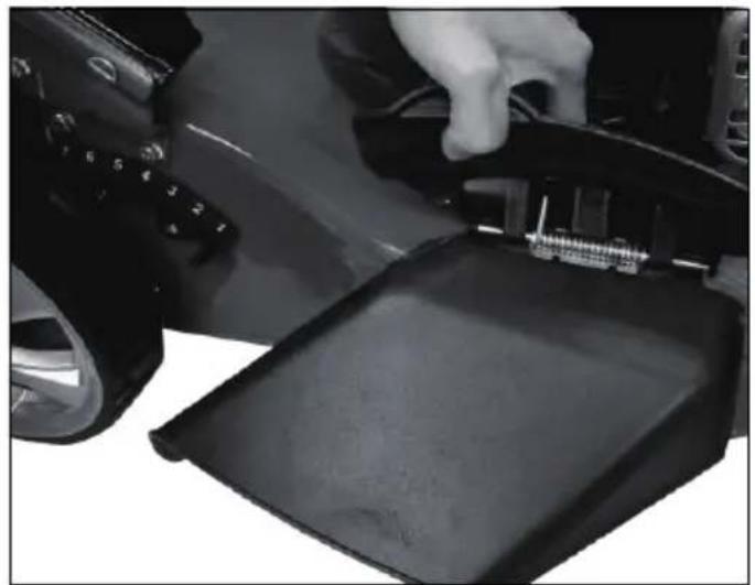
natural_image
Close-up of a hand pressing down on a black mechanical component (no visible text or symbols)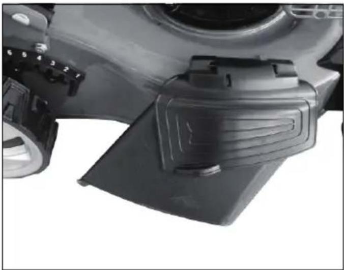
natural_image
Close-up of a mechanical component with a black plastic housing and a circular head (no visible text or symbols)7A 7B
natural_image
Close-up of a black lawn mower with visible exhaust pipes and a numbered label (24), no readable text or symbols beyond the number.
natural_image
Close-up of a black bicycle throttle valve with attached cable and adjustment knob (no text or symbols visible)8A 8B
natural_image
Silhouette of a person using a cable harness to lift a vehicle (no text or symbols visible)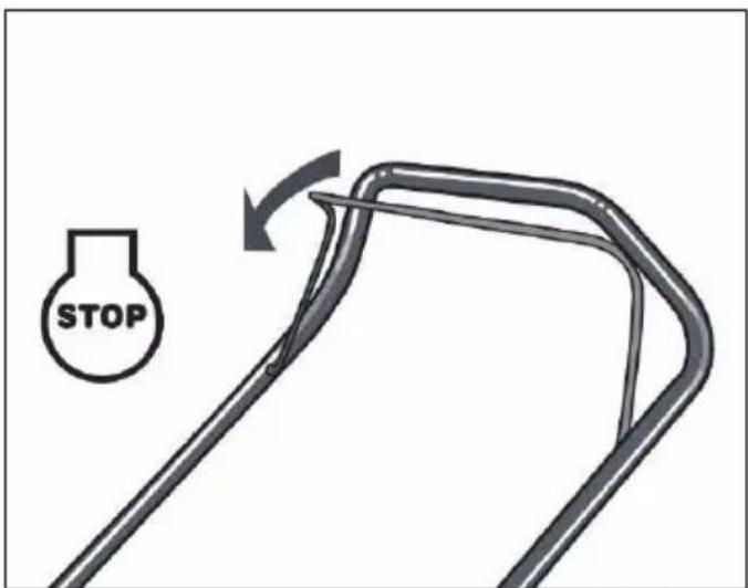
8C 8D
natural_image
Diagram of a mechanical component with an arrow indicating motion or force direction (no text or symbols present)9
natural_image
Close-up of a black industrial machine with attached cable and control panel (no visible text or symbols)10

natural_image
Close-up of a black and silver toy car wheel with attached control buttons (no visible text or symbols)11 12
natural_image
Technical line drawing of a mechanical assembly with exploded view and assembled part (no text or symbols)13
ENGLISH (Original instructions)
CONTENTS
SECTION 1 SYMBOLS MARKED ON THE PRODUCT ......9
SECTION 2 GENERAL SAFETY RULES 9
SECTION 3 PARTS DESCRIPTION ....10
SECTION 4 TECHNICAL DATA....11
SECTION 5 ASSEMBLY 11
SECTION 6 “3 IN 1”....11
SECTION 7 OPERATING INSTRUCTIONS....12
SECTION 8 MAINTENANCE INSTRUCTIONS....13
SECTION 9 LUBRICATION INSTRUCTIONS ..... 13
SECTION 10 CLEANING....13
SECTION 11 STORAGE INSTRUCTIONS (OFF SEASON)....14
SECTION 12 TROUBLESHOOTING GUIDE....15
SECTION 13 WARRANTY....16
SECTION 14 ENVIRONMENT....16
SECTION 15 EC DECLARATION OF CONFORMITY....16
Explanation of general view
| 1. Upper handle | 10. Sideward flap | 19. Bolt |
| 2. Brake control handle | 11. Deck | 20. Washer |
| 3. Choke lever | 12. Spark plug | 21. Locking knob |
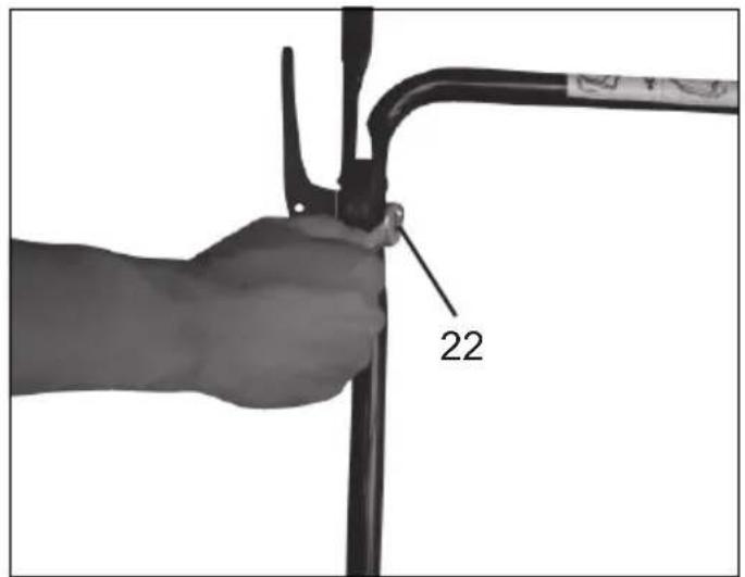
| 4. Starter handle | 13. Fuel cap | 22. Lock nut |
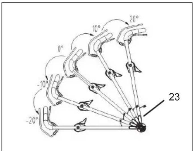
| 5. Rope guide | 14. Oil cap | 23. The angle adjusting gear |
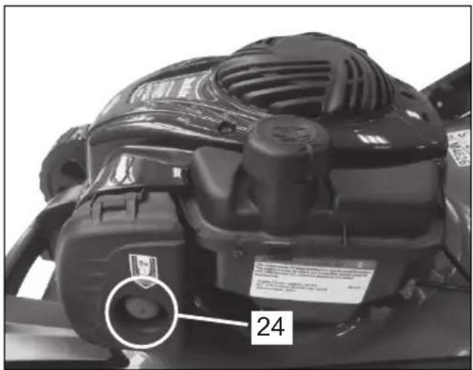
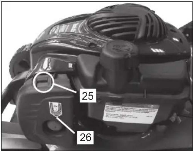
| 6. Locking lever | 15. Cable clamp | 24. Primer bulb |
| 7. Grass catch bag | 16. Lower handle | 25. Tab |
| 8. Height adjusting lever | 17. Self-drive control handle | 26. Filter cover |
| 9. Discharge channel | 18. Mulching wedge |

WARNING:
For your own safety please read this manual before attempting to operate your new unit. Failure to follow instructions can result in serious personal injury. Spend a few moments to familiarize yourself with your mower before each use.
1. SYMBOLS MARKED ON THE PRODUCT

Read operator's manual.

Keep bystanders away.
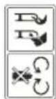
Pay more attention to the operator's hands and feet to avoid injury.
Fuel is flammable, keep fire away. Do not add fuel with running machine.

Toxic fumes; don't operate inside house.

When mowing, please wear the glasses and ear plugs to defend the operator himself.

When repairing, please pick up the spark plug, and then repair it according to the operational manual.

Caution: Engine hot.

Safety Label Found On Lawn Mower: KEEP HANDS AND FEET AWAY
2. GENERAL SAFETY RULES

WARNING: When using petrol tools, basic safety
precautions, including the following, should always be followed to reduce the risk of serious personal injury and/or damage to the unit. Read all these instruction before operating this product and retain these instructions for future reference.

WARNING: This machine produces an
electromagnetic field during operation. This field may under some circumstances interfere with active or passive medical implants. To reduce the risk of serious or fatal injury, we recommend persons with medical implants to consult their physician and the medical implant manufacturer before operating this machine.
Training
- Read the instructions carefully. Be familiar with the controls and the proper use of the equipment;
- Never allow children or people unfamiliar with these instructions to use the lawn mower. Local regulations can restrict the age of the operator;
- Never mow while people, especially children, or pets are nearby;
- Keep in mind that the operator or user is responsible for accidents or hazards occurring to other people or their property.
Preparation
- While mowing, always wear substantial footwear and long trousers. Do not operate the equipment when barefoot or wearing open sandals;
- Thoroughly inspect the area where the equipment is to be used and remove all objects which can be thrown by the machine;
-
WARNING - Petrol is highly flammable.
-
Store fuel in containers specifically designed for this purpose;
- Refuel outdoors only and do not smoke while refueling;
- Add fuel before starting the engine. Never remove the cap of the fuel tank or add petrol while the engine is running or when the engine is hot;
- If petrol is spilled, do not attempt to start the engine but move the machine away from the area of spillage and avoid creating any source of ignition until petrol vapours have dissipated;
-
Replace all fuel tank and container caps securely;
-
Replace faulty silencers;
- Before using, always visually inspect to see that the blades, blade bolts and cutter assembly are not worn or damaged. Replace worn or damaged blades and bolts in sets to preserve balance.
Operation
- Do not operate the engine in a confined space where dangerous carbon monoxide fumes can collect;
- Mow only in daylight or in good artificial light;
- Avoid operating the equipment in wet grass, where feasible;
• Always be sure of your footing on slopes; - Walk, never run;
- For wheeled rotary machines, mow across the face of slopes, never up and down;
- Exercise extreme caution when changing direction on slopes;
- Do not mow excessively steep slopes;
- Use extreme caution when reversing or pulling the lawn mower towards you;
- Stop the blade(s) if the lawn mower has to be tilted for transportation when crossing surfaces other than grass, and when transporting the lawn mower to and from the area to be mowed;
- Never operate the lawn mower with defective guards, or without safety devices, for example deflectors and/or grass catchers, in place;
- Do not change the engine governor settings or overspeed the engine;
- Disengage all blades and drive clutches before starting the engine;
- Start the engine carefully according to instructions and with feet well away from the blade(s);
- Do not tilt the lawn mower when starting the engine;
- Do not start the engine when standing in front of the discharge chute;
- Do not put hands or feet near or under rotating parts. Keep clear of the discharge opening at all times;
- Never pick up or carry a lawn mower while the engine is running;
-
Stop the engine and disconnect the spark plug wire, make sure that all moving parts have come to a complete stop and, where a key is fitted remove the key:
-
Before clearing blockages or unclogging chute;
-
Before checking, cleaning or working on the lawn mower;
-
After striking a foreign object. Inspect the lawn mower for damage and make repairs before restarting and operating the lawn mower;
- If lawn mower starts to vibrate abnormally (check immediately);
- Stop the engine and disconnect the spark plug wire, make sure that all moving parts have come to a complete stop and, where a key is fitted remove the key:
- Whenever you leave the lawn mower;
- Before refueling;
- Reduce the throttle setting during engine shut down and, if the engine is provided with a shut-off valve, turn the fuel off at the conclusion of mowing.
Maintenance and storage
- Keep all nuts, bolts and screws tight to be sure the equipment are in safe working condition;
- Never store the equipment with petrol in the tank inside a building where fumes can reach an open flame or spark;
- Allow the engine to cool before storing in any enclosure;
- To reduce the fire hazard, keep the engine, silencer, battery compartment and petrol storage area free of grass, leaves, or excessive grease;
- Check the grass catcher frequently for wear or deterioration;
- Replace worn or damaged parts for safety;
- If the fuel tank has to be drained, this should be done outdoors.

WARNING: Do not touch rotating blade.

WARNING: Refuel in a well ventilated area with
the engine stopped.
3. PARTS DESCRIPTION (Fig. A & B, C)
Including
A: Spark plug wrench
4. TECHNICAL DATA
| Model PLM4626 PLM4627 PLM4628 | |||
| Engine type B&S500E, 09P6 B&S500E, 09P6 B&S500E, 09P6 | |||
| Self-propelled no no yes | |||
| Engine displacement | 140 cm3 | 140 cm3 | 140 cm3 |
| Blade width | 460 mm | 460 mm | 460 mm |
| Rated speed | 2,800/min | 2,800/min | 2,800/min |
| Fuel tank capacity | 800 ml | 800 ml | 800 ml |
| Oil capacity | 470 ml | 470 ml | 470 ml |
| Grass catcher capacity | 60 L | 60 L | 60 L |
| Net weight | 28.0 kg | 28.4 kg | 31.2 kg |
| Height adjustment | 30-75 mm, 7 adjustment | 30-75 mm, 7 adjustment | 30-75 mm, 7 adjustment |
Differences between three models
| Model | Front handle of deck | Side discharge | Self-propelled |
| PLM4626 | √ | × | × |
| PLM4627 | √ | √ | × |
| PLM4628 | √ | √ | √ |
| Model | PLM4626 | PLM4627 | PLM4628 |
| Guaranteed sound power level at the operator's position (According to EN 836 Annex H&EN ISO 4871) | 86.9 dB (A) (K=3 dB (A)) | 86.9 dB (A) (K=3 dB (A)) | 86.9 dB (A) (K=3 dB (A)) |
| Measured sound power level | 93.7 dB (A)K=2.38 dB (A) | 93.7 dB (A)K=2.38 dB (A) | 93.7 dB (A)K=2.38 dB (A) |
| Guaranteed sound power level (According to 2000/14/EC) | 96 dB (A) | 96 dB (A) | 96 dB (A) |
| Vibration (According to EN 836 Annex G) | 4.531 m/s2K=1.5 m/s2 | 4.531 m/s2K=1.5 m/s2 | 4.531 m/s2K=1.5 m/s2 |
5. ASSEMBLY
5-1 FOLDING HANDLE
- Use the locking knob to fix the lower handlebars into the unit body. (Fig. 1A/Fig. 1B/Fig. 1C/Fig. 1D)
- Lift the two locking levers to release the upper handlebars for folding. (Fig. 1E)
- Push the locking lever closed to lock the handlebars in the operating position. (Fig. 1F)
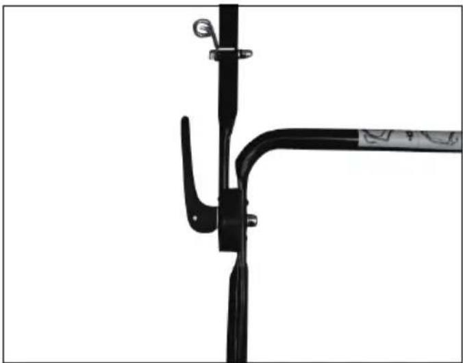
- Adjust the tension by turning the lock nut with a suitable spanner. (Fig. 1G/Fig. 1H)
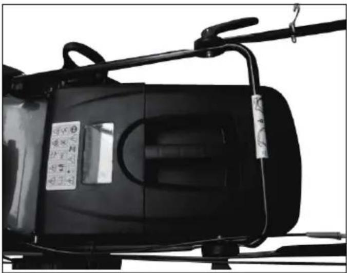
- Attach the cable-clamp to the position shown and then attach the cable. (Fig. 1I/Fig. 1J)
5-2 ADJUSTMENT FOR AN APPROPRIATE ANGLE
A) Pull the locking lever opening;
B) Rotating the upper handle centered of the angle adjusting gear for adjusted an appropriate angle into the scope -20^ to 20^ (5 position: -20^/-10^/0^/10^/20^ ) as the Fig. 2 shown;
C) Push the locking lever closed to connect the lower handle and the upper handle.
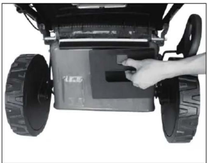
5-3 MOUNTING THE GRASS CATCHER
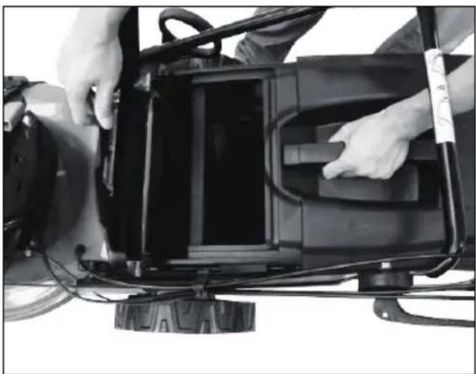
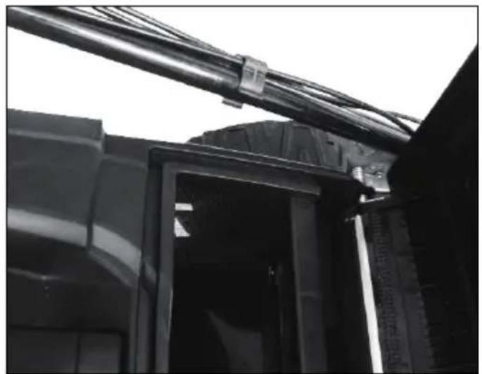
- To fit: Raise the rear cover and hitch the grass catcher on rear of mower. (Fig. 3A/Fig. 3B/Fig. 3C)
- To remove: Grasp and lift rear cover, remove grass catcher.
5-4 STARTER HANDLE
Move the starter handle from the engine to the rope guide. (Fig. 4)
5-5 HEIGHT OF CUT
Apply outward pressure to disengage lever from rack. Move lever forward or back to adjust height. (Fig. 5 and see clause 7.9)
6. "3 IN 1" (only for PLM4627, PLM4628)
These lawn mowers can be retrofitted from its normal function, based on the application purpose:
From lawn mower with rear discharge to:
- Mulching mower or as
- Side-discharge mower.
What is mulching?
When mulching, the grass is cut in one working step, then finely chopped and returned to the grass strip as natural fertilizer.
Hints for mulch-mowing:
- Regular cut-back by max. 2 cm from 6 cm to 4 cm grass height.
- Use a sharp cutting knife - Do not mow wet grass
- Set max. motor speed
- Only move at working pace
- Regularly clean mulching wedge, housing inner side and mowing blade
Starting Operation
ONE: Retrofitting for mulching mower

WARNING: Only with a stopped motor and
standstill cutter.
- Raise the rear cover and remove the grass catch bag.
- Push the mulching wedge into the deck. Lock the mulching wedge with the button into the opening on the deck. (Fig. 6A/Fig. 6B)
- Lower the rear cover again.
TWO: Resetting for side-discharge mowing

Only when motor and cutting are at standstill!
- Lift the rear cover and remove the grass catch bag.
- Mount the mulching wedge.
- Lift sideward flap for side discharge. (Fig. 7A)
- Mount the discharge channel, for side discharge on the support pin of the sideward flap. (Fig. 7A)
- Lower the sideward flap- the flap lies on the discharge channel. (Fig. 7B)
THREE: Mowing with the grass catch bag

WARNING: Only with a stopped motor and
standstill cutter.
For mowing with the grass catch bag, remove the mulching wedge and discharge channel for side discharge and mount the grass catch bag.
- Removing the mulching wedge.
- Lift rear cover and remove the mulching wedge.
- Lift sideward flap and remove discharge channel.
- Removing the discharge channel for side discharge.
- The sideward flap automatically closes the discharge opening on the housing by mean of spring force.
- Regularly clean the sideward flap and discharge opening form grass rest and stuck dirt.
- Mount the grass catch bag.
- To fit: Raise the rear cover and hitch the grass catch bag on rear of mower.
- To remove: Grasp and lift the rear cover, remove grass catch bag.
7. OPERATING INSTRUCTIONS
7-1 BEFORE STARTING
Service the engine with gasoline and oil as instructed in the separate engine manual packed in your mower. Read instructions carefully.

WARNING: Petrol is highly flammable.
Store fuel in containers specifically designed for this purpose.
Refuel outdoors only, before starting the engine and do not smoke while refueling or handling fuel.
Never remove the cap of the fuel tank or add petrol while the engine is running or when the engine is hot.
If petrol is spilled, do not attempt to start the engine but move the machine away from the area of spillage and avoid creating any source of ignition until petrol vapors have dissipated.
Replace all fuel tanks and container caps securely.
Before tipping the lawn mower to maintain the blade or drain oil, remove fuel from tank.

WARNING: Never fill fuel tank indoors, with
engine running or until the engine has been allowed to cool for at least 15 minutes after running.
7-2 TO START ENGINE AND ENGAGE BLADE
- The unit is equipped with a rubber boot over the end of the spark plug, make certain the metal loop on the end of the spark plug wire (inside the rubber boot) is fastened securely over the metal tip on the spark plug.
- Press the primer bulb 3-5 times before starting the engine. (Fig. 8A)
- When starting cool engine, turn throttle choke lever to "c" position.
When starting warm engine and operating, turn throttle choke lever to “” position. (Fig. 8B)
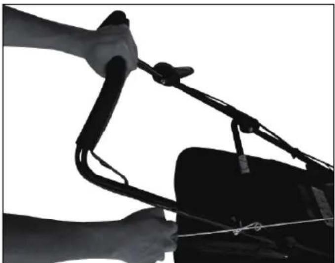
- Standing behind the unit, grasp the brake control handle and hold it against the upper handle as shown. (Fig. 8C)
- Grasp the starter handle as shown (Fig. 8C) and pull up rapidly. Return it slowly to the rope guide bolt after engine starts.
Release the brake control handle to stop the engine and blade. (Fig. 8D)

Start the engine carefully according to
instructions and with feet well away from the blade.

Do not tilt the lawn mower when starting the
engine. Start the mower on a level surface, free of high grass or obstacles.

Keep hands and feet away from the rotating
parts. Do not start the engine when standing in front of the discharge opening.
During operation, tightly hold the brake handle with both hands.
Note: During operation, when the brake handle is released, the engine will stop and thus stopping the lawn mower from operating.
7-4 TO STOP ENGINE

CAUTION: The blade continues to rotate for a
few seconds after the engine is shut off.
- Release the brake control handle to stop the engine and blade.
- Disconnect and ground the spark plug wire as instructed in the separate engine manual to prevent accidental starting while equipment is unattended.
7-5 CONNECTION FOR AUTO MOVE
For PLM4628
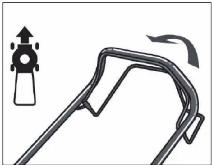
Grip the self-drive control handle, the lawn mower will move forward automatically with about 3.6 km/h (Fig. 9), release the self-drive handle, the lawn mower will stop move.

CAUTION: Your mower is designed to cut normal
residential grass of a height no more than 250 mm.
Do not attempt to mow through unusually tall dry or wet grass (e.g., pasture) or piles of dry leaves. Debris may build up on the mower deck or contact the engine exhaust presenting a potential fire hazard.
7-6 FOR THE BEST RESULTS WHEN MOWING
Clear lawn of debris. Be sure that the lawn is clear of stones, sticks, wire or other foreign objects which could be accidentally thrown out by the mower in any direction and cause serious personal injury to the operator and others as well as damage to property and surrounding objects. Do not cut wet grass. For effective mowing do not cut wet grass because it tends to stick to the underside of the deck preventing proper mowing of the grass clippings. Cut no more than 1/3 the length of the grass. The recommended cut for mowing is 1/3 the length of the grass. Ground speed will need to be adjusted so the clippings can be dispersed evenly into the lawn. For especially heavy cutting in thick grass it may be necessary to use one of the slowest speeds in order to get a clean well mowed cut. When mowing long grass you may have to cut the lawn in two passes, lowering the blade another 1/3 of the length for the second cut and perhaps cutting in a different pattern than was used the first time. Overlapping the cut a little on each pass will also help to clean up any stray clippings left on the lawn. The mower should always be operated at full throttle to get the best cut and allow it to do the most effective job of mowing. Clean underside of deck. Be certain to clean the underside of the cutting deck after each use to avoid a build-up of grass, which would prevent proper mulching. Mowing leaves. The mowing of leaves can also be beneficial to your lawn. When mowing leaves make sure they are dry and are not laying too thick on the lawn. Do not wait for all the leaves to be off the trees before you mow.

WARNING: If you strike a foreign object, stop the Remove wire from spark plug, thoroughly inspect over for any damage and repair the damage before and operating the mower. Extensive vibration of water during operation is an indication of damage.
The unit should be promptly inspected and repaired.
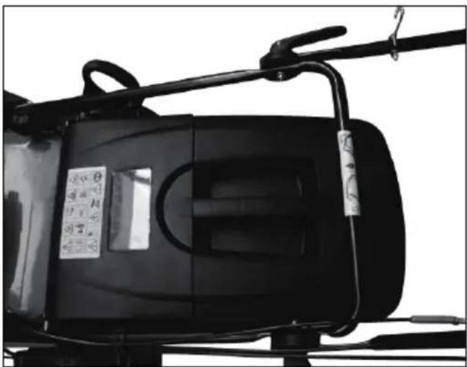
7-7 GRASS CATCHER
There is a window on the rear cover. You can see the condition of grass catcher through the window. If the catcher is full of grass; you will empty and clean the bag, make sure it is clean and ensure its meshwork is ventilated. (Fig. 10)
7-8 DECK
The underside of the mower deck should be cleaned after each use to prevent a buildup of grass clippings, leaves, dirt or other matter. If this debris is allowed to accumulate, it will invite rust and corrosion, and may prevent proper mulching. The deck may be cleaned by tilting the mower and scraping clean with a suitable tool (make certain the spark plug wire is disconnected).
7-9 HEIGHT ADJUSTMENT INSTRUCTIONS

CAUTION: Do not at any time make any
adjustment to lawn mower without first stopping the engine and disconnecting the spark plug wire.

CAUTION: Before changing mowing height, stop
mower and disconnect spark plug cable.
Your mower is equipped with a central height adjustment lever offering 7 height positions.
- Stop mower and disconnect spark plug cable before changing mower cutting height.
- The central height adjustment lever offers you 7 different height positions.
- To change the height of cut, squeeze adjuster lever toward the wheel, moving up or down to selected height. (Fig. 11)
All wheels will be in the same height of cut.
8. MAINTENANCE INSTRUCTIONS
SPARK PLUG
Use only original replacement spark plug. For best results, replace the spark plug every 100 hours of use.
9. LUBRICATION INSTRUCIONS

CAUTION: DISCONNECT SPARK PLUG
BEFORE SERVICING.
- WHEELS - Lubricate the ball bearings in each wheel at least once a season with a light oil.
- ENGINE - Follow engine manual for lubrication instructions.
10. CLEANING

CAUTION: Do not hose engine. Water can
damage engine or contaminate the fuel system.
- Wipe deck with dry cloth.
- Hose under deck by tilting the mower so that the spark plug is up.
10-1 ENGINE AIR CLEANER

CAUTION: Do not allow dirt or dust to clog the air filter foam element. The engine air cleaner element must be serviced (cleaned) after 25 hours normal mowing. The foam element must be serviced regularly if the mower is used in dry dusty conditions.
To CLEAN AIR FILTER
- Lift the tabs on top of the filter cover.
- Remove the filter cover.
- Wash filter element in soap water. DO NOT USE GASOLINE!
- Air dry filter element.
- Place a few drops of SAE30 oil on the foam filter and squeeze tightly to remove any excess oil.
- Reinstall filter.
NOTE: Replace filter if frayed, torn, damaged or unable to be cleaned. (Fig. 12)
10-2 CUTTING BLADE

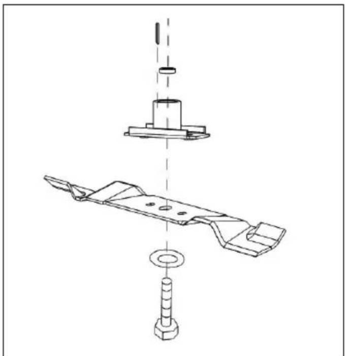
CAUTION: Be sure to disconnect and ground the spark plug wire before working on the cutting blade to prevent accidental engine starting. Protect hands by using heavy gloves or a rag to grasp the cutting blades. Tip mower as specified in separate engine manual. Remove the hex bolt and washer which hold the blade and blade adapter to the engine crankshaft. Remove the blade and adapter from the crankshaft.

WARNING: Periodically inspect the blade adapter for cracks, especially if you strike a foreign object. Replace when necessary.
For best results your blade should be sharp. The blade may be resharpened by removing it and either grinding or filing the cutting edge keeping as close to the original bevel as possible. It is extremely important that each cutting edge receives an equal amount of grinding to prevent an unbalanced blade. Improper blade balance will result in excessive vibration causing eventual damage to the engine and mower. Be sure to carefully balance blade after sharpening. The blade can be tested for balance by balancing it on a round shaft screwdriver. Remove metal from the heavy side until it balances evenly.
Before reassembling the blade and the blade adapter to the unit, lubricate the engine crankshaft and the inner surface of the blade adapter with light oil. Install the blade adapter on the crankshaft. Refer to Fig. 13. Place the blade with the part number facing away from the adapter. Align the washer over the blade and insert the hex bolt. Tighten the hex bolt to the torque listed below:
10-3 BLADE MOUNTING TORQUE
Center bolt 35 Nm - 45 Nm, to insure safe operation of your unit. All nuts and bolts must be checked periodically for correct tightness.
After prolonged use, especially in sandy soil conditions, the blade will become worn and lose some of the original shape. Cutting efficiently will be reduced and the blade should be replaced. Replace with an approved factory replacement blade only. Possible damage resulting from blade unbalance condition is not the responsibility of the manufacturer.
When you change the blade, you must use the original type marked on the blade (Makita 263001451) (to order the blade, please contact your local dealer or call our company, see cover page).
10-4 ENGINE
Refer to the separate engine manual for engine maintenance instructions.
Maintain engine oil as instructed in the separate engine manual packed with your unit. Read and follow instructions carefully.
Service air cleaner as per separate engine manual under normal conditions.
Clean every few hours under extremely dusty conditions. Poor engine performance and flooding usually indicates that the air cleaner should be serviced.
To service the air cleaner, refer to the separate engine manual packed with your unit.
The spark plug should be cleaned and the gap reset once a season. Spark plug replacement is recommended at the start of each mowing season; check engine manual for correct plug type and gap specifications.
Clean the engine regularly with a cloth or brush. Keep the cooling system (blower housing area) clean to permit proper air circulation which is essential to engine performance and life. Be certain to remove all grass, dirt and combustible debris from muffler area.
11. STORAGE INSTRUCTIONS (OFF SEASON)
The following steps should be taken to prepare lawn mower for storage.
- Empty the tank after the last mowing of the season.
a) Empty the petrol tank with a suction pump.

CAUTION: Do not drain the petrol in closed rooms, in close proximity of open fire, etc. Do not smoke! Petrol fumes can cause explosion or fire.
b) Start the engine and let it run until it has used up all remaining petrol and stalls.
c) Remove the spark plug. Use an oilcan to fill approx. 20 ml oil into the combustion chamber. Operate the
starter to evenly distribute the oil in the combustion chamber. Replace the spark plug.
- Clean and grease the lawn mower carefully as described above under "LUBRICATION INSTRUCIONS".
- Slightly grease the cutter to avoid corrosion.
- Store the lawn mower in a dry, clean and frost-protected place, out of reach of unauthorized persons.

CAUTION: The engine must have completely down before storing the lawn mower.

NOTE:
- When storing any type of power equipment in an unventilated or material storage shed:
- Care should be taken to rust-proof the equipment. Using a light oil or silicone, coat the equipment, especially cables and all moving parts.
- Be careful not to bend or kink cables.
- If the starter rope becomes disconnected from rope guide on handle, disconnect and ground the spark plug wire, depress the blade control handle and pull the starter rope out from engine slowly. Slip the starter rope into the rope guide bolt on handle.
Transport
Turn the engine off. Ensure not to bend or damage the cutter when pushing the lawn mower over obstacles.
- TROUBLESHOOTING GUIDE
| PROBLEM PROBABLE | CAUSE CORRECTIVE ACTION | |
| Engine does not start. Throttle choke | not in the correct position for the prevailing conditions. | Move throttle choke to correct position. |
| Fuel tank is empty. Fill tank with fuel: refer to ENGINE OWNERS MANUAL. | ||
| Air cleaner element is dirty. Clean air cleaner element: refer to ENGINE OWNERS MANUAL. | ||
| Spark plug loose. Tighten spark plug to 25-30 Nm. | ||
| Spark plug wire loose or disconnected from plug. | Install spark plug wire on spark plug. | |
| Spark plug gap is incorrect. Set gap between electrodes at 0.7 to 0.8 mm. | ||
| Spark plug is defective. Install new, correctly gapped plug: refer to ENGINE OWNERS MANUAL. | ||
| Carburetor is flooded with fuel. Remove air cleaner element and pull starter rope continuously until carburetor clears itself and install air cleaner element. | ||
| Faulty ignition module. Contact the service agent. | ||
| Engine difficult to start or loses power. | Dirt, water, or stale fuel tank. Drain fuel and clean tank. Fill tank with clean, fresh fuel. | |
| Vent hole in fuel tank cap is plugged. Clean or replace fuel tank cap. | ||
| Air cleaner element is dirty. Clean air cleaner element. | ||
| Engine operates erratically. Spark plug is defective. Install new, correctly gapped plug: refer to ENGINE OWNERS MANUAL. | ||
| Spark plug gap is incorrect. Set gap between electrodes at 0.7 to 0.8 mm. | ||
| Air cleaner element is dirty. Clean air cleaner element: refer to ENGINE OWNERS MANUAL. | ||
| Engine idles poorly. | Air cleaner element is dirty. Clean air cleaner element: refer to ENGINE OWNERS MANUAL. | |
| Air slots in engine shroud are blocked. | Remove debris from slots. | |
| Cooling fins and air passages under engine blower housing are blocked. | Remove debris from cooling fins and air passages. | |
| Engine skips at high speed. | Gap between electrodes of spark plug is too close. | Set gap between electrodes at 0.7 to 0.8 mm. |
| Engine overheats. | Cooling air flow is restricted. | Remove any debris from slots in shroud, blower housing, air passages. |
| Incorrect spark plug. | Install RC12YC spark plug and cooling fins on engine. | |
| Mower vibrates abnormally. | Cutting assembly is loose. | Tighten blade. |
| Cutting assembly is unbalanced. | Balance blade. | |
13. WARRANTY
This product is warranted in accordance with legal regulations for a 12 months period effective from the date of purchase by the first user.
This warranty covers all material or production failures, it does not include defects from normal wear & tear parts, such as bearings, brushes, cables, plugs or accessories like drills, drill bits, saw blades etc.; damage or defects resulting from abuse, accidents or alterations; nor the costs for transport.
We reserve the right to reject any claim where the purchase cannot be verified or when it is clear that the product was not maintained properly. (Clean ventilation slots, carbon brushes serviced regularly.)
Your purchase ticket must be kept as proof for date of purchase.
Your un-dismantled tool must be returned to your dealer in an acceptably clean state, in its original blow molded case if applicable to unit, accompanied by your proof of purchase.
14. ENVIRONMENT
Should your machine need replacement after extended use, do not put it in the domestic waste but dispose of it in an environmentally safe way.
15. EC DECLARATION OF CONFORMITY
For European countries only
We Makita Corporation as the responsible
manufacturer declare that the following Makita machine(s):
Designation of Machine: Petrol Lawn Mower
Model No./Type: PLM4626, PLM4627, PLM4628
Specifications: See "4. TECHNICAL DATA"
are of series production and
Conforms to the following European Directives:
2004/108/EC, 2006/42/EC, 2000/14/EC & 2005/88/EC
And are manufactured in accordance with following
standards or standards documents:
EN ISO 14982, EN836
The technical documentation is kept by:
Makita International Europe Ltd.
Technical Department,
Michigan Drive, Tongwell,
Milton Keynes, Bucks MK15 8JD, England
The conformity assessment procedure required by
Directive 2000/14/EC was in Accordance with Annex V.
Notified body:
Measured sound power level: 93.7 dB (A)
Guaranteed sound power level: 96 dB (A)
Model: PLM4627
Measured sound power level: 93.7 dB (A)
Guaranteed sound power level: 96 dB (A)
Model: PLM4628
Measured sound power level: 93.7 dB (A)
Guaranteed sound power level: 96 dB (A)
-
- 2013

Tomoyasu Kato
Director
Makita Corporation
3-11-8, Sumiyoshi-cho,
Anjo, Aichi, 446-8502, JAPAN
SECTION 15 DÉCLARATION DE CONFORMITÉ CE....27
Descriptif
Technical Department,
Michigan Drive, Tongwell,
Milton Keynes, Bucks MK15 8JD, Angleterre
3-11-8, Sumiyoshi-cho,
Anjo, Aichi, 446-8502, JAPAN
KAPITEL 1 SYMBOLE AM PRODUKT....29
1. SYMBOLE AM PRODUKT

Technical Department,
Michigan Drive, Tongwell,
Milton Keynes, Bucks MK15 8JD, England
3-11-8, Sumiyoshi-cho,
Anjo, Aichi, 446-8502, JAPAN
2004/108/EC, 2006/42/EC, 2000/14/EC e 2005/88/EC
Technical Department,
Michigan Drive, Tongwell,
Milton Keynes, Bucks MK15 8JD, Inghilterra
3-11-8, Sumiyoshi-cho,
Anjo, Aichi, 446-8502, JAPAN
Technical Department, Michigan Drive, Tongwell,
Milton Keynes, Bucks MK15 8JD, Inglaterra
Tomoyasu Kato Director
Makita Corporation
3-11-8, Sumiyoshi-cho,
Anjo, Aichi, 446-8502, JAPAN
2004/108/EC, 2006/42/EC, 2000/14/EC e 2005/88/EC
Technical Department, Michigan Drive, Tongwell, Milton Keynes, Bucks MK15 8JD, Inglaterra
Tomoyasu Kato Director
Makita Corporation
3-11-8, Sumiyoshi-cho,
Anjo, Aichi, 446-8502, JAPAN
SVENSKA (Originalanvisningar)
INNEHÅLL
SEKTION 1 SYMBOLER MÄRKTA PÅ PRODUKTEN 70
SEKTION 2 ALLMÄNNA SÄKERHETSANVISNINGAR....70
SEKTION 3 BESKRIVNING AV DELAR ....71
SEKTION 4 TEKNISK DATA 72
SEKTION 5 MONTERING....72
SEKTION 6 "3 | 1"....72
SEKTION 7 ANVÄNDARANVISNINGAR....73
SEKTION 8 UNDERHÅLLSANVISNINGAR....74
SEKTION 9 SMÖRJNINGSANVISNINGAR....75
SEKTION 10 RENGÖRING....75
SEKTION 11 FÖRVARINGSANVISNINGAR (AVSTÄLLNING)....75
SEKTION 12 FELSÖKNINGSGUIDE....77
SEKTION 13 GARANTI....77
SEKTION 14 MILJÖ....78
SEKTION 15 EU-DEKLARATION OM ÖVERENSSTÄMMELSE. 78
5-1 FÄLLBART HANDTAG
7-2 STARTA MOTORN OCH KOPPLA IN KNIVEN
Technical Department,
Michigan Drive, Tongwell,
Milton Keynes, Bucks MK15 8JD, England
3-11-8, Sumiyoshi-cho,
Anjo, Aichi, 446-8502, JAPAN
1. SYMBOLENE PÅ PRODUKTET

FORSIKTIG: KOBLE FRA TENNPLUGGEN
F∅R VEDLIKEHOLD.
- HJUL – Smør kulelagrene i hvert hjul med en lett olje minst en gang i sesongen.
- MOTOR – Følg angivelsene i motorens bruksanvisning for smøring.
10. RENGJ∅RING

FORSIKTIG: Ikke sprut vann på motoren. Vannet
2004/108/EF, 2006/42/EF, 2000/14/EF og 2005/88/EF
Michigan Drive, Tongwell,
Milton Keynes, Bucks MK15 8JD, England
3-11-8, Sumiyoshi-cho,
Anjo, Aichi, 446-8502, JAPAN
OSA 4 TEKNISET TIEDOT 92
OSA 5 KOKOAMINEN....92
OSA 6 MONITOIMILEIKKURI 92
OSA 7 KÄYTTÖ....93
OSA 8 KUNNOSSAPITO....94
OSA 9 VOITELU 94
OSA 10 PUHDISTUS....95
OSA 11 SÄILYTYS (TALVIAIKANA)....95
OSA 12 VIANMÄÄRITYSOPAS....97
OSA 13 TAKUU .97
OSA 14 YMPÄRISTÖNÄKÖKOHDAT....98
OSA 15 EY-VAATIMUSTENMUKAISUUSVAKUUTUS 98
Technical Department,
Michigan Drive, Tongwell,
Milton Keynes, Bucks MK15 8JD, England
3-11-8, Sumiyoshi-cho,
Anjo, Aichi, 446-8502, JAPAN
Technical Department, Michigan Drive, Tongwell,
Milton Keynes, Bucks MK15 8JD, Anglija
3-11-8, Sumiyoshi-cho,
Anjo, Aichi, 446-8502, JAPAN
LIETUVIŲ KALBA (Originali instrukcija)
TURINYS
1 SKYRIUS ANT GAMINIO PAŽYMĚTI ŽENKLAI....110
2 SKYRIUS BENDROSIOS SAUGOS TAISYKLĖS. 110
3 SKYRIUS DALIŲ APRAŠYMAS 111
4 SKYRIUS TECHNINIAI DUOMENYS 112
5 SKYRIUS MONTAVIMAS 112
6 SKYRIUS „Trys viename“ 112
7 SKYRIUS NAUDOJIMO INSTRUKCIJA 113
8 SKYRIUS TECHNINĖS PRIEŽIŪROS INSTRUKCIJA....115
9 SKYRIUS TEPIMO INSTRUKCIJA....115
10 SKYRIUS VALYMAS....115
11 SKYRIUS SAUGOJIMO INSTRUKCIJA (NE SEZONO METU) 116
12 SKYRIUS TRIKČIŲ ŠALINIMO VADOVAS....117
13 SKYRIUS GARANTIJA 118
14 SKYRIUS APLINKOSAUGA....118
15 SKYRIUS EB ATITIKTIES DEKLARACIJA....118
Bendrasis aprašymas
Technical Department,
Michigan Drive, Tongwell,
Milton Keynes, Bucks MK15 8JD, England (Anglija)
3-11-8, Sumiyoshi-cho,
Anjo, Aichi, 446-8502, JAPAN
Technical Department,
Michigan Drive, Tongwell,
Milton Keynes, Bucks MK15 8JD, Inglismaa
3-11-8, Sumiyoshi-cho,
Anjo, Aichi, 446-8502, JAPAN
2004/108/WE, 2006/42/WE, 2000/14/WE i
2005/88/WE
Technical Department,
Michigan Drive, Tongwell,
Milton Keynes, Bucks MK15 8JD, Wielka Brytania
3-11-8, Sumiyoshi-cho,
Anjo, Aichi, 446-8502, JAPAN
3-11-8, Sumiyoshi-cho,
Anjo, Aichi, 446-8502, JAPAN
7-3 PRACOVNÉ POSTUPY
2004/108/ES, 2006/42/ES, 2000/14/ES a 2005/88/ES
Technical Department,
Michigan Drive, Tongwell,
Milton Keynes, Bucks MK15 8JD, Anglicko
3-11-8, Sumiyoshi-cho,
Anjo, Aichi, 446-8502, JAPAN
5-1 SKLÁPĚCÍ DRŽADLO
5-3 MONTÁŽ SBĚRACÍHO KOŠE
Technical Department,
Michigan Drive, Tongwell,
Milton Keynes, Bucks MK15 8JD, England
3-11-8, Sumiyoshi-cho,
Anjo, Aichi, 446-8502, JAPAN
SLOVENŠČINA (Izvirna navodila)
KAZALO
DEL 1 SIMBOLI NA IZDELKU 170
DEL 2 SPLOŠNA VARNOSTNA PRAVILA....170
DEL 3 OPIS DELOV....171
DEL 4 TEHNIČNI PODATKI....172
DEL 5 MONTAŽA....172
DEL 6 „3 V 1“ 172
DEL 7 NAVODILA ZA UPRAVLJANJE....173
DEL 8 NAVODILA ZA VZDRŽEVANJE 174
DEL 9 NAVODILA ZA MAZANJE 174
DEL 10 ČIŠČENJE....175
DEL 11 NAVODILA ZA SHRANJEVANJE (IZVEN SEZONE) 175
DEL 12 PRIROČNIK ZA ODPRAVLJANJE TEŽAV 177
DEL 13 GARANCIJA 178
DEL 14 OKOLJE 178
DEL 15 ES IZJAVA O SKLADNOSTI 178
Splošna razlaga
2004/108/ES, 2006/42/ES, 2000/14/ES in 2005/88/ES
Technical Department,
Michigan Drive, Tongwell,
Milton Keynes, Bucks MK15 8JD, Anglija
3-11-8, Sumiyoshi-cho,
Anjo, Aichi, 446-8502, JAPAN
SHQIP (Udhëzimet originale)
PËRMBAJTJA
SEKSIONI 1 SIMBOLET E SHËNUARA NË PRODUKT....180
SEKSIONI 2 RREGULLA TË PËRGJITHSHME TË SIGURISË....180
SEKSIONI 3 PËRSHKRIMI I PJESËVE....181
SEKSIONI 4 TË DHËNA TEKNIKE ....182
SEKSIONI 5 MONTIMI....182
SEKSIONI 6 “3 NË 1”....182
SEKSIONI 7 UDHËZIMET E PËRDORIMIT....183
SEKSIONI 8 UDHËZIMET E MIRËMBAJTJES ....184
SEKSIONI 9 UDHËZIMET PËR VAJOSJEN 185
SEKSIONI 10 PASTRIMI 185
SEKSIONI 11 UDHËZIMET PËR RUAJTJEN (MBYLLJA E STINËS)....186
SEKSIONI 12 UDHËZUESI PËR ZGJIDHJEN E PROBLEMEVE....187
SEKSIONI 13 GARANCIA 188
SEKSIONI 14 MJEDISI 188
SEKSIONI 15 DEKLARATA E PAJTUESHMËRISË ME KE-NË....188
7-7 MBLEDHËSJA E BARIT
Technical Department,
Michigan Drive, Tongwell,
Milton Keynes, Bucks MK15 8JD, England
3-11-8, Sumiyoshi-cho,
Anjo, Aichi, 446-8502, JAPAN
2004/108/EC, 2006/42/EC, 2000/14/EC и 2005/88/EC
Technical Department,
Michigan Drive, Tongwell,
Milton Keynes, Bucks MK15 8JD, England
3-11-8, Sumiyoshi-cho,
Anjo, Aichi, 446-8502, JAPAN
HRVATSKI (Originalne upute)
SADRŽAJ
ODJELJAK 1 SIMBOLI KOJIMA JE PROIZVOD OZNAČEN 200
ODJELJAK 2 OPĆA SIGURNOSNA PRAVILA....200
ODJELJAK 3 OPIS DIJELOVA .201
ODJELJAK 4 TEHNIČKI PODACI....202
ODJELJAK 5 MONTAŽA....202
ODJELJAK 6 „3 U 1“.202
ODJELJAK 7 UPUTE ZA RUKOVANJE .....203
ODJELJAK 8 UPUTE ZA ODRŽAVANJE .....204
ODJELJAK 9 UPUTE ZA PODMAZIVANJE .....205
ODJELJAK 10 ČIŠĆENJE....205
ODJELJAK 11 UPUTE ZA SKLADIŠTENJE (IZVAN SEZONE) 205
ODJELJAK 12 VODIČ ZA OTKLANJANJE POTEŠKOĆA .207
ODJELJAK 13 JAMSTVO....208
ODJELJAK 14 ZAŠTITA OKOLIŠA....208
ODJELJAK 15 EC IZJAVA O SUKLADNOSTI....208
Technical Department,
Michigan Drive, Tongwell,
Milton Keynes, Bucks MK15 8JD, Engleska
3-11-8, Sumiyoshi-cho,
Anjo, Aichi, 446-8502, JAPAN
МАКЕДОНСКИ (Оригинални упатства)
СОДРЖИНА
ДЕЛ 1 СИМБОЛИ НА ПРОИЗВОДОТ....210
ДЕЛ 2 ОПШТИ БЕЗБЕДНОСНИ ПРАВИЛА .....210
ДЕЛ 3 ОПИС НА ДЕЛОВИТЕ .....211
2004/108/EC, 2006/42/EC, 2000/14/EC и 2005/88/EC
Technical Department,
Michigan Drive, Tongwell,
Milton Keynes, Bucks MK15 8JD, England
3-11-8, Sumiyoshi-cho,
Anjo, Aichi, 446-8502, JAPAN
Technical Department,
Michigan Drive, Tongwell,
Milton Keynes, Bucks MK15 8JD, Anglia
3-11-8, Sumiyoshi-cho,
Anjo, Aichi, 446-8502, JAPAN
3-11-8, Sumiyoshi-cho,
Anjo, Aichi, 446-8502, JAPAN
Technical Department,
Michigan Drive, Tongwell,
Milton Keynes, Bucks MK15 8JD, England
3-11-8, Sumiyoshi-cho,
Anjo, Aichi, 446-8502, JAPAN
Technical Department,
Michigan Drive, Tongwell,
Milton Keynes, Bucks MK15 8JD, Англія
3-11-8, Sumiyoshi-cho,
Anjo, Aichi, 446-8502, JAPAN
Makita Corporation
Anjo, Aichi, Japan
PLM4626-25L-1013 www.makita.com