USER MANUAL MB 756 YC VIKING
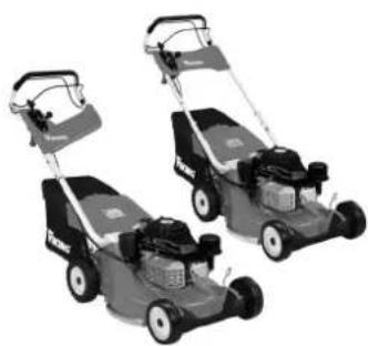
MB 756 GS, MB 756 YC, MB 756 YS
VIKING®
natural_image
Three Viking lawn mower machines shown in black and gray, no visible text or symbols on the machines themselves.
MB 756.0 GS MB 756.0 YC MB 756.0 YS
DE Gebrauchsanleitung
EN Instruction manual
FR Manuel d'utilisation
NL Gebruiksaanwijzing
IT Istruzioni per l'uso
ES Manual de instrucciones
PT Manual de utilização
PL Instrukcja obsługi
HU Használati útmutató
RU Инструкция по эксплуатации

2
MB 756 YC
natural_image
Technical line drawing of a lawn mower with labeled component A (no text or symbols beyond label)

27


MB 756.0 YC, MB 756.0 YS

97/68/EC, 2000/14/EC, 2004/108/EC, 2006/42/EC
MB 756.0 YS 98 dB(A)
MB 756.0 YC 98 dB(A)
Langkampfen,
2015-01-02 (JJJJ-MM-TT)
VIKING GmbH

natural_image
Simple line drawing of a mechanical component with a cylindrical top and rectangular base (no text or symbols)
Nächster Service
Datum: ____ ____ ____ ____ ____
Thank you for choosing a VIKING quality product.
This product has been produced using state-of-the-art production methods and extensive quality assurance procedures, because our goal is only achieved if you, the customer, are satisfied with your machine.
If you have any questions concerning your machine, please contact your dealer or our sales agency directly.
I hope that your VIKING machine will give you great enjoyment.

Dr. Peter Pretzsch
Management
1. Table of contents
Notes on the instruction manual 34
General 34
Instructions for reading the instruction manual 34
Machine overview 34
For your safety 34
General 34
Refilling the tank – handling petrol 36
Clothing and equipment 36
Transporting the machine 36
Before operation 36
Working with your machine 37
Maintenance and repairs 39
Storage for prolonged periods without operation 40
Disposal 40
Description of symbols 40
Standard equipment
Preparing the machine for operation
Assembling the handlebar 41
Installing protective sleeve 41
Single-wheel cutting height adjustment 41
Height adjustment of the handlebar 42
Fuel and engine oil 42
Assembling the grass catcher bag 42
Attaching and detaching the grass catcher bag 42
Blade brake clutch (BBC) 42
Notes on working with the machine
Operating the machine 43
Starting the engine 43
Engaging the mowing blade 43
Disengaging the mowing blade 44
Checking the blade brake clutch (BBC) 44
Switching on self-propulsion 44
Switching off self-propulsion 44
Stopping the engine 44
Grass catcher bag with anti-dust screen 44
Maintenance 45
Cleaning the machine 45
Wheels 45
Engine 46
Gearbox 46
Blade brake clutch maintenance 46
Checking blade wear 46
Removing and installing the mowing blade 46
Sharpening the mowing blade 47
Maintaining cables 47
Storage and periods of inoperation (winter break) 48
Transport 48
Securing the machine (lashing) 48
Lifting or carrying the machine 48
Environmental protection 48
Minimising wear and preventing damage 48
Standard spare parts 49
Technical specifications 50
Troubleshooting 50
Service schedule 5
Handover confirmation 52
Service confirmation 52
2. Notes on the instruction manual
2.1 General
This instruction manual constitutes original manufacturer's instructions in the sense of EC Directive 2006/42/EC.
VIKING is continually striving to further develop its range of products; we therefore reserve the right to make alterations to the form, technical specifications and equipment level of our standard equipment.
For this reason, the information and illustrations in this manual are subject to alterations.
2.2 Instructions for reading the instruction manual
Illustrations and texts describe specific operating steps.
All symbols which are affixed to the machine are explained in this instruction manual.
Viewing direction:
Viewing direction when "left" and "right" are used in the instruction manual: the user is standing behind the machine and is looking forwards in the direction of travel.
Section reference:
References to relevant sections and subsections for further descriptions are made using arrows. The following example shows a reference to a section: ( 2.1)
Designation of text passages:
The instructions described can be identified as in the following examples.
Operating steps which require intervention on the part of the user:
- Release bolt (1) using a screwdriver, operate lever (2)...
General lists:
– Use of the product for sporting or competitive events
Texts with added significance:
Text passages with added significance are identified using the symbols described below in order to especially emphasise them in the instruction manual:

Danger
Risk of accident and severe injury to persons. A certain type of behaviour is necessary or must be avoided.

Warning
Risk of injury to persons. A certain type of behaviour prevents possible or probable injuries.

Caution
Minor injuries or material damage can be prevented by a certain type of behaviour.

Note
Information for better use of the machine and in order to avoid possible operating errors.
Texts relating to illustrations:
Illustrations relating to use of the machine can be found in the front of this instruction manual.
The camera symbol serves to link the figures on the illustration pages with the corresponding text passages in the instruction manual.

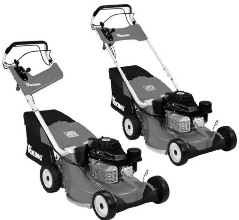
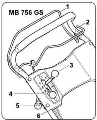
3. Machine overview
1 Blade stop lever
2 Self-propulsion lever
3 Throttle lever
4 MB 756.0 GS: Gearshift lever
4 MB 756.0 YS, MB 756.0 YC: Driving speed lever
5 Blade clutch lever
6 Handlebar
7 Screw for handlebar height adjustment
8 Single-wheel cutting height adjustment
9 Bumper
10 Spark plug socket
11 Discharge flap
12 Grass catcher bag with anti-dust screen
13 Identification plate
4. For your safety
4.1 General

These safety regulations must be observed when working with the machine.

Read the entire instruction manual before using the machine for the first time. Keep the instruction manual in a safe
place for future reference.
Observe the operating and maintenance instructions contained in the separate engine instruction manual.
These safety precautions are essential for your safety, however the list is not exhaustive. Always use the machine in a reasonable and responsible manner and be aware that the user is responsible for accidents involving third parties or their property.
Make sure that you are familiar with the controls and use of the machine.
The machine must only be used by persons who have read the instruction manual and are familiar with operation of the machine. The user should seek expert and practical instruction prior to initial operation. The user must receive instruction on safe use of the machine from the vendor or another expert.
During this instruction, the user should be made aware that the utmost care and concentration are required for working with the machine.

Risk of death from suffocation!
Packaging material is not a toy - danger of suffocation! Keep packaging material away from children.
Only give or lend the machine, including any accessories, to persons who are familiar with this model and how to operate it. The instruction manual forms part of the machine and must always be provided to persons borrowing it.
The machine must only be operated by persons who are well rested and in good physical and mental condition. If your health is impaired, you should consult your doctor to determine whether working with the machine is possible. The machine should not be operated after the consumption of alcohol, drugs or medications which impair reactions.
Never allow children under the age of 16 to use the machine. Local regulations may specify a minimum age for users.
This machine is not suitable for use by persons (in particular children) with impaired physical, sensory or mental faculties or those lacking the appropriate experience and/or knowledge, unless supervised by a person responsible for their safety or having received instructions on use of the machine from such person. Children must be supervised, in order to ensure that they do not play with the machine.
Caution – risk of accident!
The lawn mower is only intended for mowing lawns. Its use for other purposes is not permitted and may be dangerous or result in damage to the machine.
Due to the physical danger to the user, the lawn mower must not be used for the following applications (incomplete list):
- For trimming bushes, hedges and shrubs.
- For cutting creepers.
- For tending lawn roofs and balcony boxes.
- For shredding or chopping tree or hedge cuttings.
- For clearing paths (vacuuming, blowing).
- For levelling earth mounds, e.g. mole hills.
- For transporting clippings, except in the grass catcher box intended for this purpose.
For safety reasons, any modification to the machine, except the proper installation of accessories approved by VIKING, is forbidden and results in voiding of the warranty cover. Information regarding approved accessories can be obtained from your VIKING specialist dealer.
In particular, any tampering with the machine which increases the power output or speed of the engine or motor is forbidden.
It is not permitted to transport objects, animals or persons, particularly children, on the machine.
Particular care is required during use in public green spaces, parks, sports fields, along roads and in agricultural and forestry businesses.

Caution: Danger to health due to vibrations!
Excessive exposure to
vibrations can result in damage to the cardiovascular or nervous system, particularly in persons with cardiovascular problems. Please consult a physician if you experience symptoms that may have been caused by vibrational loads.
Symptoms of this kind principally affect the fingers, hands or wrists and include (incomplete list):
- numbness,
- p a i n ,
- muscular weakness,
- skin discolouration,
– unpleasant tingling sensation.
4.2 Refilling the tank – handling petrol

Danger to life!
Petrol is poisonous and extremely inflammable.
Petrol must only be stored in appropriate, tested containers (canisters). Always screw on the fuel tank and canister caps properly and tightly. Defective caps must be replaced for safety reasons.
Never use beverage bottles or similar for disposal or storage of fuels and lubricants. Persons, particularly children, could be tempted to drink out of them.

Keep petrol away from sparks, naked flames, pilot lights, heat sources, and other ignition sources. Do not smoke!
Refill the tank out-of-doors and do not smoke during refilling.
Before refilling the tank, stop the engine and allow it to cool.
Open the tank ventilation screw before removing the tank cap.
Refilling with petrol must be performed before the engine is started. When the engine is running or is hot, the tank cap must not be removed and the tank must not be refilled with petrol.
Do not fill the fuel tank completely, but fill to approx. 4 cm below the edge of the filler neck so that the fuel has room to expand.
If petrol is spilled, the engine must only be started after the petrol-contaminated area has been cleaned. All attempts at starting must be avoided until the petrol fumes have dispersed (wipe dry).
Any spilt fuel must be wiped up immediately.
Clothing must be changed if it comes into contact with petrol.
Only close the tank ventilation screw and fuel cock for transport and before placing the machine in the service position.
Never store the machine with petrol in the tank inside a building. The resulting petrol fumes could come into contact with naked flames or sparks and could be ignited.
If it is necessary to drain the tank, this must be done out of doors.
4.3 Clothing and equipment

Always wear sturdy footwear with high-grip soles when working. Never work barefoot
or, for example, in sandals.

Always wear hearing protection when working with the machine.

Also always wear sturdy gloves and tie up and secure long hair (headscarf, cap, etc.) when performing maintenance and
cleaning work or when transporting the machine.

Wear suitable safety glasses when sharpening the mowing blade.
Always wear long trousers and tight-fitting clothing when operating the machine.
Never wear loose clothes which may become caught on moving parts (control levers) – do not wear jewellery, ties or scarves.
4.4 Transporting the machine
Always wear gloves in order to prevent injuries due to sharp-edged and hot components.
Do not transport the machine with the engine running. Switch off the engine, let the blades come to a standstill, close the tank ventilation screw and fuel cock and remove the spark plug socket prior to transport.
Only transport the machine once the engine has cooled down.
Use suitable loading aids (loading ramps, lifters).
Do not drop the machine.
Secure the machine and any machine components being transported (e.g. grass catcher box) on the load floor using fastening material of adequate size (belts, ropes, etc.).
Avoid contact with the mowing blade when lifting and carrying the machine.
Observe the information in the section "Transport". It describes how to lift and lash the machine. ( 12.)
When transporting the machine, always observe regional legislation, especially regarding load security and the transport of objects on load floors.
4.5 Before operation
Make sure that only persons who are familiar with the instruction manual are permitted to use the machine.
Check the fuel system (particularly visible parts such as e.g. tank, tank cap, hose connections) before operating the
machine. In the event of any leaks or damage, do not start the engine – fire hazard!
Have the machine repaired by a specialist dealer prior to operation.
Observe the local regulations regarding permitted operating times for gardening power tools with combustion engines or electric motors.
Carefully inspect the complete area on which the machine is to be used and remove any stones, sticks, wires, bones and other foreign objects which could be thrown up by the machine. Obstacles (e.g. tree stumps, roots) can be easily overlooked in long grass.
For this reason, mark all foreign objects (obstacles) which are hidden in the lawn and cannot be removed before commencing work with the machine.
Defective and all other worn or damaged parts must be removed before using the machine. Replace any illegible or damaged danger signs and warnings on the machine. Your VIKING specialist has a supply of replacement stickers and all the other spare parts.
The machine must only be used in good operating condition. Before each use, check whether:
– The machine is properly assembled.
- The cutting tool and the entire cutting unit (mowing blade, fastening attachments, mowing deck housing) are in good condition. In particular check for secure fastening, damage (notches or cracks) and wear. (⇒ 11.6)
– The tank cap is properly attached.
– The tank and fuel-carrying parts, as well as the tank cap are in good condition.
- The safety devices (e.g. blade brake clutch, discharge flap, housing, handlebar, protective grille) are in good condition and working properly.
- The grass catcher bag is undamaged and correctly installed; a damaged grass catcher bag must not be used.
– The oil tank cap is screwed on properly.
Carry out any necessary work or consult a specialist dealer. VIKING recommends VIKING specialist dealers.
4.6 Working with your machine

Never work when animals or persons, particularly children, are in the danger area.
The switch and safety devices installed in the machine must not be removed or bypassed. In particular, never secure the blade stop lever to the handlebar (e.g. by tying it).

Caution – risk of injury!
Never put hands or feet on or underneath rotating parts.
Never touch the rotating blade.
Always keep away from the discharge opening.
Always observe the safety distance provided by the handlebar. The handlebar must always be installed correctly and must not be modified. Never operate the machine with the handlebar folded down.
Never attach any objects to the handlebar (e.g. work clothing).
Only work during the day or with good artificial light.
Do not operate the machine in the rain or during thunder storms, particularly when there is a risk of lightning strike.
The risk of accidents is higher if the ground is damp due to increased danger of slipping.
Particular caution should be exercised during working in order to prevent slipping. If possible, avoid using the machine when the ground is damp.
Exhaust gases:

Danger to life through poisoning!
In the case of nausea, headache, impaired vision (e.g. decreasing field of view) hearing disorder, dizziness, decreasing power of concentration, stop working immediately. These symptoms may be caused by excessively high exhaust gas concentrations.

The machine generates poisonous exhaust gases when the engine is running. The gases contain poisonous
carbon monoxide, a colourless and odourless gas, as well as other pollutants. The engine must never be operated in closed or poorly ventilated spaces.
Starting:
Exercise care when starting and observe the instructions contained in the section "Initial operation of machine". ( 10.) In particular, check operation of the blade brake clutch before starting work. ( 10.4)
The machine must not be tilted during start-up.
Disengage the mowing blade before starting. Do not actuate the self-propulsion lever during starting.
Do not start the engine if the discharge chute is not covered by the discharge flap or the grass catcher box.
Working on slopes:
Always work across and back on slopes, never up and down.
If the user loses control when mowing up and down, there is a risk of being run over by the machine.
Be particularly careful when changing direction on a slope.
Always ensure good stability on slopes and avoid mowing on excessively steep slopes.
For safety reasons, the machine must not be used on slopes with an inclination of more than 25^ (46.6%). Risk of injury! A slope inclination of 25^ corresponds to a vertical height increase of 46.6 cm for a 100 cm horizontal distance.

In order to ensure an adequate oil supply for the engine, the information in the accompanying engine instruction manual must be additionally observed when using the machine on slopes.
Working:

Risk of injury!
Never place your hands or feet above, underneath or on rotating parts.

Do not attempt to examine the blade while the lawn mower is operating. Never open the
discharge flap and/or remove the grass catcher box when the mowing blade is running. Rotating blades can cause injury.
Only operate the machine at walking speed – never run when working with the machine. Working quickly with the machine increases the risk of injury due to stumbling, slipping, etc.
Be particularly careful when turning the machine around or pulling it towards you. Risk of stumbling!
Use the machine with great care when working near rubbish dumps, ditches and embankments. In particular, ensure that you maintain sufficient distance to such danger areas.
Objects hidden in the turf (lawn sprinkler systems, posts, water valves, foundations, electrical wires, etc.) must be avoided. Never run over any such foreign objects.

Beware of the cutting tool running on for several seconds before coming to a standstill.
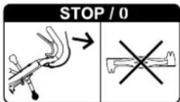
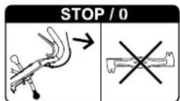
STOP
Stop the engine, allow the work tool to come to a complete
standstill and detach the spark plug socket
– before leaving the machine unattended,
– before re-filling the tank. Allow the engine to cool down before re-filling the tank.
Fire hazard!
– before remedying blockages, including those in the discharge chute,
– before lifting or carrying the machine,
– before transporting the machine,
– before carrying out any work on the mowing blade,
– before checking or cleaning the machine or before carrying out any other work (e.g. folding down the handlebar) on it,
– after hitting a foreign object or if the lawn mower begins to vibrate excessively. In these cases check the machine, in particular the cutting unit (blade, blade shaft, blade fastening) for damage and carry out the necessary repairs before restarting and working with the machine.

Risk of injury!
Strong vibrations are generally an indication of a fault.
In particular, the lawn mower must not be operated with a damaged or bent crankshaft or mowing blade. If you do not have the appropriate expertise, have the necessary repairs carried out by a specialist dealer (VIKING recommends VIKING specialist dealers).
Disengage the mowing blade
- When driving the machine to and from the area to be mowed or when pushing it for this purpose
– Before pushing machine onto an area not covered in grass or before driving it onto such an area
- If tilting of the mower is necessary when pushing or driving it over an area other than grass
– Before adjusting the cutting height
– Before opening the discharge flap or removing the grass catcher bag
4.7 Maintenance and repairs

Before beginning cleaning, adjustment, repair and maintenance operations, park the machine on firm, level ground, stop the engine, allow it to cool down and detach the spark plug socket.

Risk of injury due to the mowing blade!
Pulling the recoil starter rope with the mowing blade engaged starts the work tool rotating. Always ensure sufficient distance between the mowing blade and your body, particularly your hands and feet, when you pull the recoil starter rope.
Allow the machine to cool down before working on or around the engine, exhaust manifold or muffler in particular. Temperatures of 80^ C and above can be reached. Danger of burns!
Direct contact with engine oil can be dangerous. Engine oil must not be spilled. VIKING recommends leaving the task of topping up engine oil or performing engine oil changes to a VIKING specialist dealer.
Cleaning:
The complete machine must be cleaned thoroughly following use. ( 11.1)
Close the tank ventilation screw and fuel cock before placing the machine in the cleaning position.
Remove accumulated clipping deposits using a stick. Clean the underside of the mower with water and a brush.
Never use high-pressure cleaners and do not clean the machine under running water (e.g. using a garden hose).
Do not use aggressive cleaning agents. These can damage plastics and metals, impairing the safe operation of your VIKING machine.
In order to prevent fire hazards, keep the area around the air vents, cooling ribs and the area of the exhaust free from e.g. grass, straw, moss, leaves or escaping grease.
Maintenance operations:
Only maintenance operations described in this instruction manual may be carried out. Have all other work performed by a specialist dealer.
If you do not have the necessary expertise or auxiliary equipment, please always contact a specialist dealer.
VIKING recommends that you have maintenance operations and repairs performed exclusively by a VIKING specialist dealer.
VIKING specialist dealers regularly attend training courses and are provided with technical information.
Only use tools, accessories or attachments approved for this machine by VIKING or technically identical parts. Otherwise, there may be a risk of accidents resulting in personal injury or damage to the machine. If you have any questions, please consult a specialist dealer.
The characteristics of original VIKING tools, accessories and spare parts are optimally adapted to the machine and the user's requirements. Genuine VIKING spare parts can be recognised by the VIKING spare parts number, by the VIKING lettering and, if present, by the VIKING spare parts symbol. On smaller parts, only the symbol may be present.
For safety reasons, fuel-carrying components (fuel line, fuel cock, fuel tank, tank cap, connections, etc.) must be checked regularly for damage and leaks and replaced by a technician if necessary (VIKING recommends VIKING specialist dealers).
Always keep warning and information stickers clean and readable. Damaged or missing stickers must be replaced by new, original plates from your VIKING specialist dealer. If a component is replaced with a new component, ensure that the new component is provided with the same stickers.
Only perform work on the cutting unit when wearing thick work gloves and exercising extreme care.
Ensure that all nuts, pins and screws (in particular the blade fastening screw) are securely tightened so that the machine is in a safe operating condition.
Check the complete machine and the grass catcher box for wear or damage on a regular basis, particularly before extended periods when the machine is not in use (e.g. over winter). For safety reasons, worn or damaged parts must be replaced immediately to ensure that the machine is always in a safe operating condition.
Never alter the basic setting of the engine or run at excessive engine speeds.
Components or guards that are removed for maintenance operations must be properly reinstalled immediately.
4.8 Storage for prolonged periods without operation
Allow the engine to cool before storing the machine in an enclosed space.
Store the machine with empty fuel tank and open tank ventilation screw as well as the fuel reserve in a lockable and well-ventilated room.
Ensure that the machine is protected from unauthorised use (e.g. by children).
Never store the machine with petrol in the tank inside a building. The resulting petrol fumes could come into contact with naked flames or sparks and could be ignited.
If the tank has to be emptied (e.g. to store the machine before the winter break), this should only be done out of doors (e.g. by running the tank empty).
Thoroughly clean the machine before storage (e.g. winter break).
Only store the machine with the spark plug socket disconnected.
Store the machine in good operational condition.
4.9 Disposal
Waste products such as used engine oil, gearbox oil or fuel, used lubricants, filters, batteries and similar wearing parts can be harmful to people, animals and the environment, and must consequently be disposed of properly.
Consult your recycling centre or your specialist dealer for information on the proper disposal of waste products. VIKING recommends VIKING specialist dealers.
Ensure that old machines are properly disposed of. Render the machine unusable prior to disposal. In order to prevent accidents, remove the ignition lead, empty the fuel tank and drain the engine oil in particular.
Risk of injury due to the mowing blade!
Always store an old lawn mower in a safe place prior to scrapping. Ensure that the machine and particularly the mowing blade are kept out of the reach of children.
5. Description of symbols

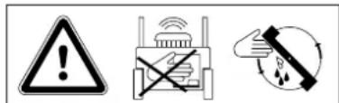
Caution!
Read the instruction manual before initial use.
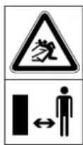
Risk of injury!
Keep other persons out of the danger area.
Risk of injury!
Detach the spark plug socket before performing work on the cutting tool or maintenance and cleaning work.
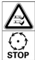
Risk of injury!
Keep your hands and feet away from the blades.
Cutting tool runs on for several seconds after switching off (engine/blade brake).

Wear hearing protection when working.
Caution – risk of injury!
Never reach into the working area of the blade when the engine is running.
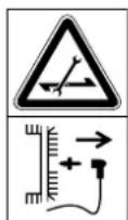
Speed adjustment:
MB 756.0 YS, MB 756.0 YC:

Maximum speed

Minimum speed
Throttle:

Choke position

Start position

Stop position
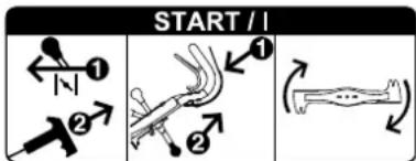
Start the engine, engage the mowing blade.
Disengage the mowing blade.
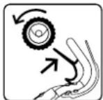
Switch on self-propulsion.
6. Standard equipment

Item Designation Qty.
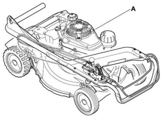
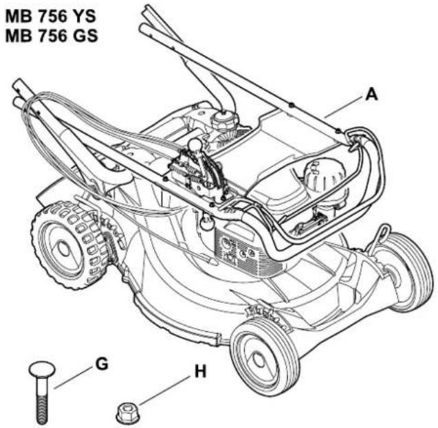
| A | Basic unit with handlebar | 1 |
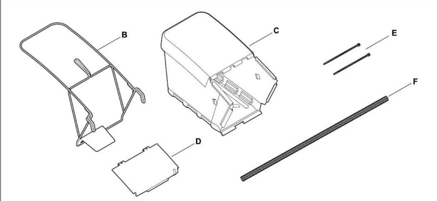
| B | Grass catcher bag frame | 1 |
| C | Grass catcher bag fabric | 1 |
| D | Grass catcher bag flap | 1 |
| E | Cable tie | 2 |
| F | Protective sleeve | 1 |
| - | Instruction manual | 1 |
Item Designation Qty.
Engine instruction manual 1
MB 756.0 GS, MB 756.0 YS:
| G | Flat head bolt | 4 |
| H | Lock nut | 4 |
7. Preparing the machine for operation

Risk of injury:
Observe the safety instructions in the section "For your safety" ( 4.).
- Place the machine on level and firm ground when performing all the operations described.
7.1 Assembling the handlebar
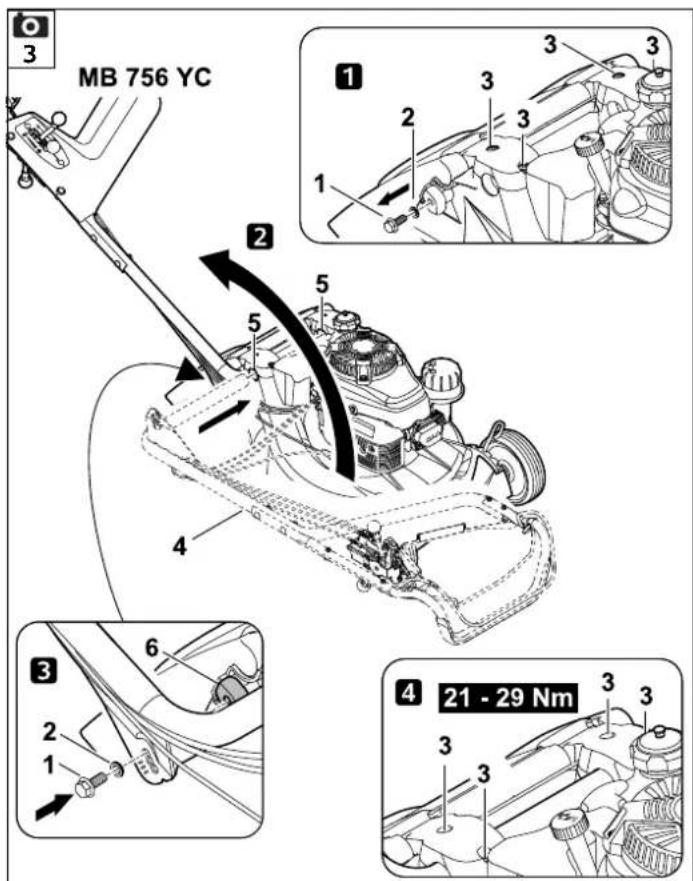
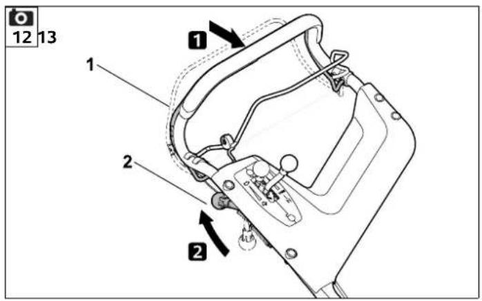
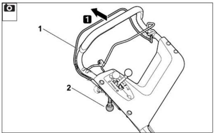
MB 756.0 YC:
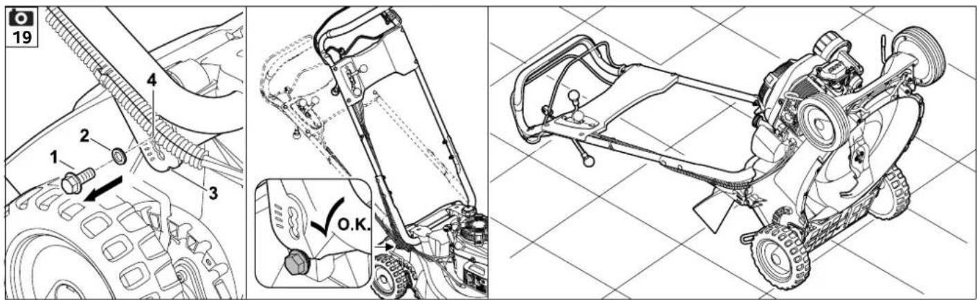
- Remove screw (1) with washer (2). Loosen screws (3).
- 2Push handlebar (4) into handlebar attachment (5) and fold up until the slot in the handlebar is above the bore in the housing, making sure that the cables are lying correctly (see illustration).
- Install screw (1) with washer (2), making sure that the screw also extends into guard plate (6).
- 4 Tighten screws (3) to 21 - 29 Nm. Set the handlebar to the desired working height and hold, tighten screw (1).
- Check correct assembly:
The handlebar must be firmly located with the cables to the rear and outside of the handlebar.
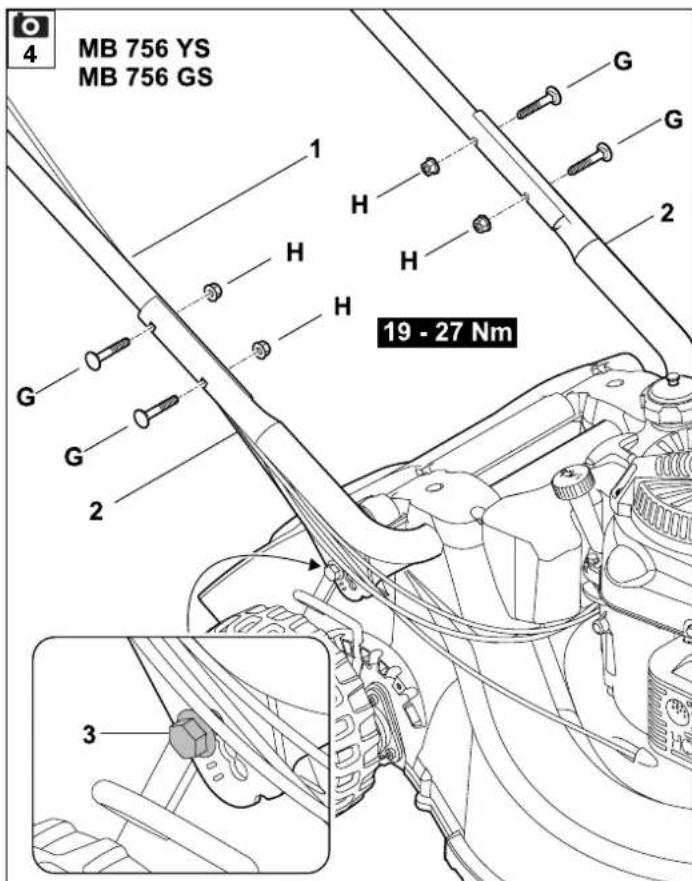
MB 756.0 GS, MB 756.0 YS:
• 1 Guide upper handlebar (1) with the open ends into lower handlebars (2) and hold. Insert bolts (G) from the outside inwards through the bores, fit lock nuts (H) and tighten to 19 - 27 Nm.
- 2 Set the handlebar to the desired working height and hold, tighten screw (3).
- Check correct assembly:
The upper handlebar must be firmly connected to the lower handlebar with the cables to the rear and outside of the handlebar.
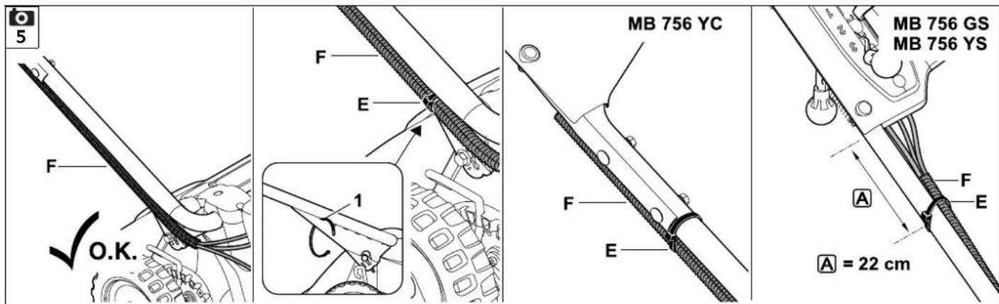
7.2 Installing protective sleeve
- Insert all cables in protective sleeve (F).
- Guide cable tie (E) through the top opening in right lower handlebar (1) and use to fasten protective sleeve (F).
- Fasten protective sleeve (F) to right upper handlebar with cable tie (E) as shown.
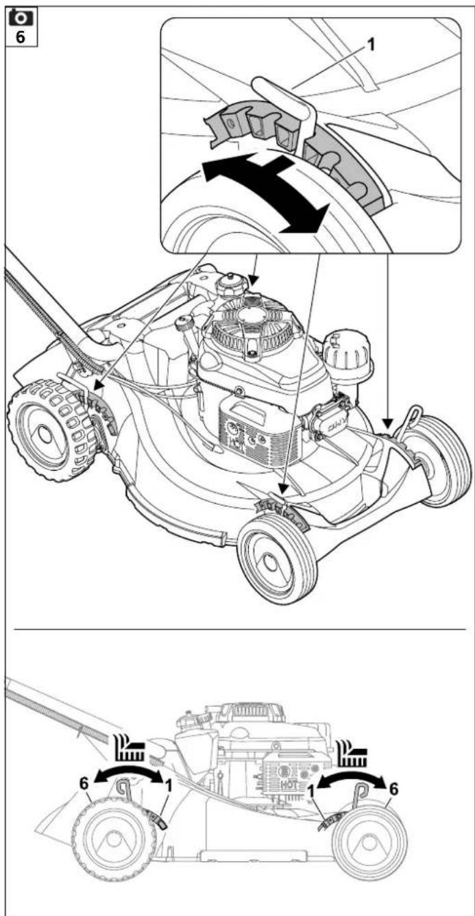
7.3 Single-wheel cutting height adjustment
The cutting height can be adjusted to six different positions at each wheel using a corresponding lever.
Lowest cutting height (1): 25 mm
Highest cutting height (6): 90 mm
Setting the cutting height:
- Push lever (1) towards the wheel, set to the desired position and allow to engage in the corresponding notch.


Repeat this procedure on all four wheels.

Avoid damage to the machine!
To prevent the machine tipping over, set the cutting height on the rear wheels first and then on the front wheels.
Caution must also be exercised when setting a lower cutting height because the entire weight of the machine then rests on the last wheel.
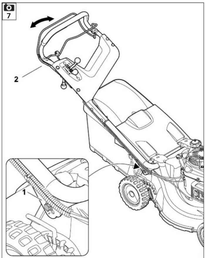
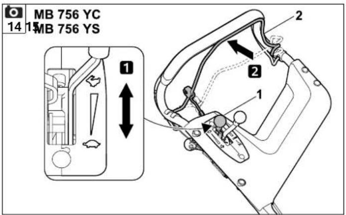
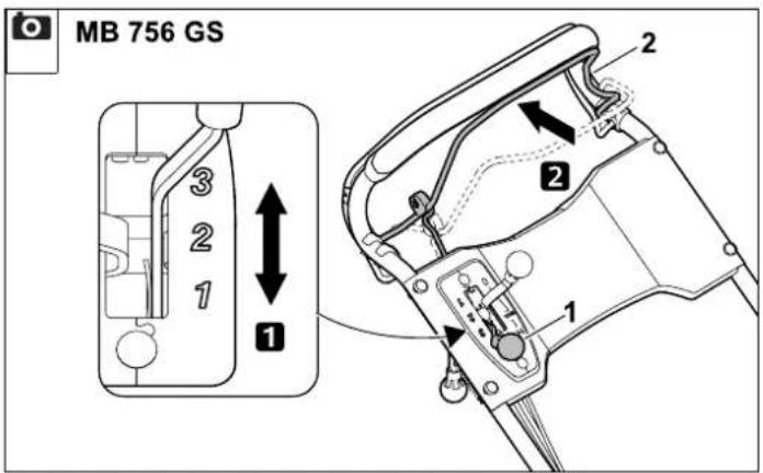
7.4 Height adjustment of the handlebar

The working height of the handlebar can be adjusted to 3 levels.
- Remove screw (1).
- Grip handlebar (2) with both hands, adjust to a pleasant working height by moving it upwards or downwards and hold in position.
• Install screw (1) and tighten.
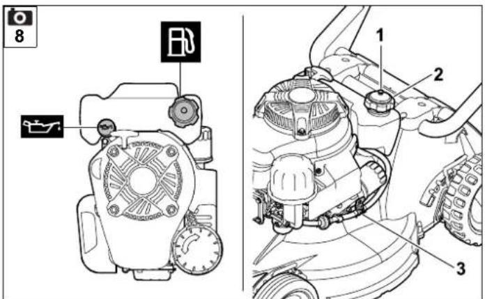
7.5 Fuel and engine oil


Avoid damage to the machine!
Top up engine oil before starting for the first time. Use a suitable filling aid when topping up the engine oil and when refuelling (e.g. funnel).
Engine oil
Please consult the engine instruction manual for the type of engine oil to be used and the oil capacity.


Check the oil filling level at regular intervals (see engine instruction manual).
Avoid exceeding or falling below the correct oil level.
Screw on the oil tank cap properly before operating the engine.
Fuel
Use only fresh, environmentally friendly, good quality fuel:
- Unleaded petrol

Please consult the engine instruction manual for precise details on the fuel quality/octane rating.
See the section "Technical specifications" for details about the fuel tank capacity. ( 17.)
Topping up fuel
- Open tank ventilation screw (1).
- Unscrew tank cap (2).
- Top up fuel (use a funnel).
- Screw tank cap (1) back on again.

Open tank ventilation screw (1) and fuel cock (3) before operating the engine.
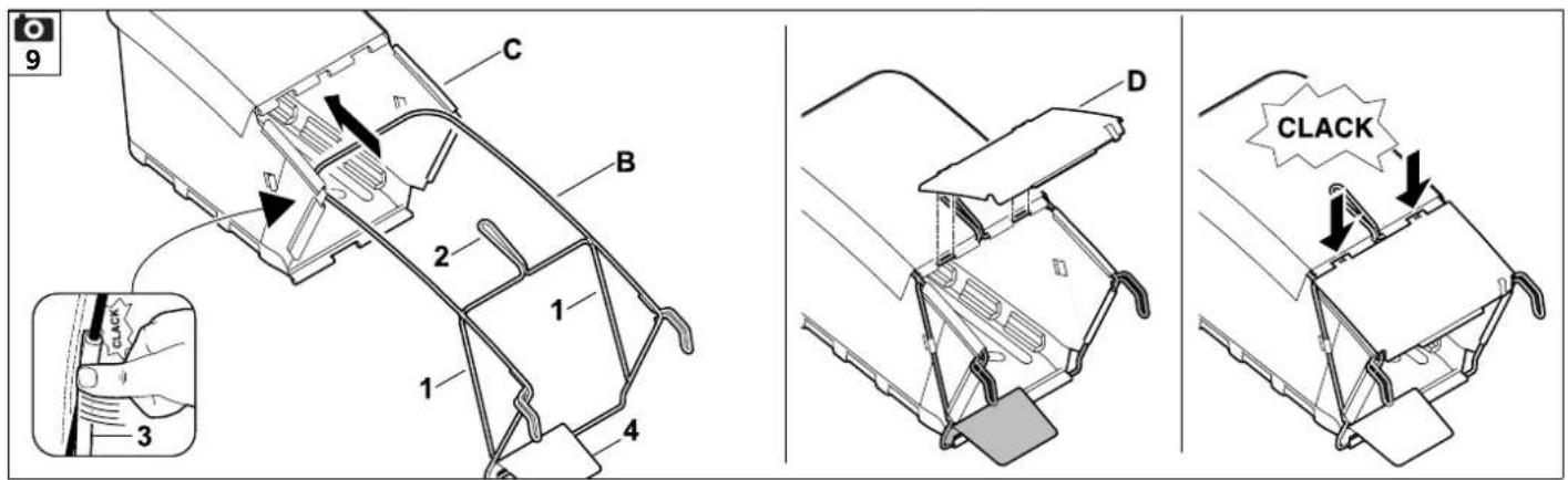
7.6 Assembling the grass catcher bag
- Pull grass catcher bag fabric (C) over grass catcher bag frame (B) as shown. The struts (1) and handle (2) must be located on the outside of the fabric.

- Position integrated plastic sleeves (3) on the grass catcher bag frame and press them into place. Start by pressing under guiding plate (4) of the grass catcher bag frame.
- First attach flap (D) on the left, then on the right of the grass catcher bag frame, then snap them in on both sides by pressing firmly.
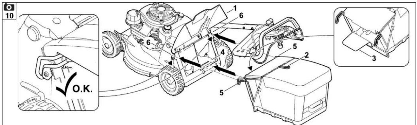
7.7 Attaching and detaching the grass catcher bag

Attaching:
- Open discharge flap (1) and hold it open.
- Hold the grass catcher bag at handle (2) and guide into ejection chute (4) with guiding plate (3).
- Place brackets (5) on mountings (6) on the left and right between the machine and handlebar and attach the grass catcher bag with a gentle tug.
- Release discharge flap (1).
Detaching:
- Lift discharge flap (1).
- Hold grass catcher bag at handle (2) and detach.
- Close discharge flap (1).
8. Blade brake clutch (BBC)
Your lawn mower is equipped with a blade brake clutch (BBC).

This means that the mowing blade stops within a short time after it is disengaged, but the engine keeps running.
In order to prevent injuries or damage to the machine, ensure that you are familiar with operation of the BBC system prior to initial use.
Two-hand operation:
The mowing blade can only be engaged as follows with the engine running: Press blade stop lever (1) towards the handlebar and hold, then pull blade clutch lever (2) upwards with the other hand and allow it to engage.

Risk of injury!
For safety reasons, the lever must never be disabled, e.g. by tying it to the handlebar.
Operation of the blade brake clutch must be checked before each use. ( 10.4)

Avoid damage to the machine!
Avoid overloading as this can result in greater wear to the blade brake clutch and consequently to overheating. ( 9.)
9. Notes on working with the machine
Avoid overloading of the blade brake clutch
An overload can occur
- if mowing is continued when the grass catcher bag is full.
– if the mowing channel is blocked.
- if mowing at excessive speed in high grass.
If the mowing blade is blocked, the grass is no longer cut and the engine cuts out.
For this reason, never mow when the mowing channel is blocked or the grass catcher bag is full; adapt the driving speed to the conditions. Use a mulching kit (special accessory) if necessary.
Completion of work
Upon completing work, always remove combustible material (grass, leaves, etc.) from the housing and engine to prevent a fire hazard.
A perfect, thick lawn is achieved by
– Mowing at low driving speeds.
– Mowing regularly and keeping the grass short.
- Not cutting the lawn too short in hot, dry conditions as it will be burnt by the sun and become unsightly.
- Using a sharp mowing blade – mowing blade should therefore be sharpened regularly (specialist dealer).
- Changing the cutting direction regularly.
10. Operating the machine

Risk of injury!
Carefully read and observe the "For your safety" section before operating the machine. (⇔ 4.)
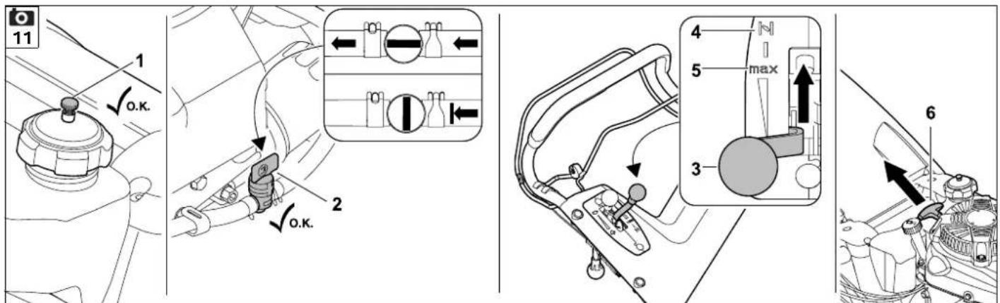
10.1 Starting the engine
- Check the oil and fuel levels.
(⇒ 7.5)
- Open tank ventilation screw (1) and fuel cock (2).

- Set throttle lever (3) to the Choke position (4) when the engine is cold.
Set throttle lever (3) to the Start position (5) when the engine is warm or during hot weather.


- Pull recoil starter rope (6) slowly to the point of compression resistance and then pull vigorously to arm's length to prevent kickback.
Slowly release the cable so that it can gradually be rolled up by the starter. Repeat the starting procedure until the engine starts.
- Set throttle lever (3) to the Start position (5).


Risk of injury!
If the recoil starter rope recoils at high speed, the hand and arm will be pulled towards the engine faster than the cable can be released. This can result in broken bones, crush injuries and sprains.
10.2 Engaging the mowing blade


Avoid damage to the machine!
Do not engage the mowing blade in tall grass and only engage it at the maximum engine speed.
Always engage it quickly in order to prevent unnecessary wear to the blade clutch.
- 1 Press blade stop lever (1) to the handlebar and hold.
- 2 Pull blade clutch lever (2) back to the stop and allow to engage.
- Keep blade stop lever (1) pressed when working.
10.3 Disengaging the mowing blade

• 1 Release blade stop lever (1).
The blade clutch lever (2) is released and returns automatically to its initial position. The mowing blade is disengaged and braked, the engine continues to run.
10.4 Checking the blade brake clutch (BBC)
Operation of the blade brake clutch must be checked three times before starting work.
- Engage the mowing blade with the engine running. ( 10.2)
A running mowing blade generates a clearly audible wind noise.
- Disengage the mowing blade (release the blade stop lever). ( 10.3)
The blade brake clutch disengages the mowing blade from the engine drive and brakes it. This procedure is accompanied by stopping of the wind noise and must not exceed 3 seconds. No wind noise must be audible when the blade is stopped.
Measuring the run-on time
The run-on time corresponds to the duration of the wind noise following disengagement. This can be measured using a stopwatch.
Should the blade brake clutch not work as described (e.g. run-on time too long or continuing audible wind noise when the mowing blade is disengaged), the machine must not be operated.

Risk of injury!
In this case, switch off the engine, detach the spark plug socket and have the necessary repairs performed by trained personnel. VIKING recommends VIKING specialist dealers.
10.5 Switching on self-propulsion
MB 756.0 YC, MB 756.0 YS
The lawn mowers are equipped with a hydrostatic gearbox. The speed can be continuously regulated when self-propulsion is switched on.
- Start the engine. (⇒ 10.1)
- 1 Set the required speed using driving speed lever (1).
VIKING recommends moving off slowly and therefore selecting a low speed.
- 2Pull self-propulsion lever (2) to the handlebar and hold.
Self-propulsion is switched on and the lawn mower moves forwards.
Drive speed:
Continuously from

0,5 km/h
to

6,0 km/h
MB 756.0 GS:
The lawn mower is equipped with a three-speed gearbox. The three forward gears can be freely selected with self-propulsion engaged.
- Start the engine. (⇒ 10.1)

- 1 Engage the required gear with gearshift lever (1).
VIKING recommends moving off slowly and therefore engaging 1st gear.
- 2 Pull self-propulsion lever (2) to the handlebar and hold.
Self-propulsion is switched on and the lawn mower moves forwards.
Drive speed:
1st gear: 2,5 km/h
2nd gear: 3,7 km/h
3rd gear: 5,0 km/h
10.6 Switching off self-propulsion

- 1 Release self-propulsion lever (1) to switch off self-propulsion.
10.7 Stopping the engine
- To stop the engine, move throttle lever (1) to the Stop position (2).

10.8 Grass catcher bag with anti-dust screen

An anti-dust screen (1) is attached on the upper side of the grass catcher bag, which prevents fine dust from being blown upwards in the direction of the user.
Level indicator:
The centre of the anti-dust screen is lifted slightly through the air flow which is generated by the rotary motion of the mowing blade and is responsible for filling the grass catcher bag.
When the grass catcher bag is full, this
flow of air is reduced and the anti-dust screen drops down onto the grass catcher bag.
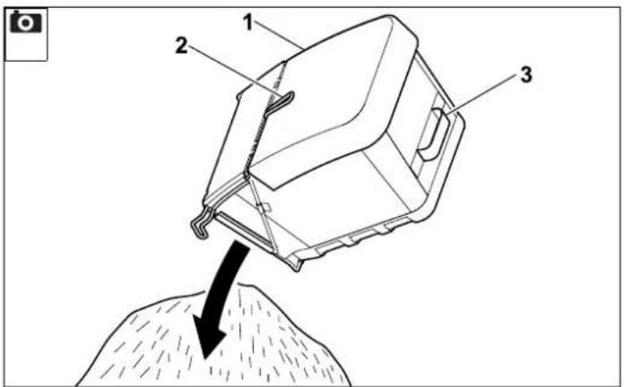
Emptying the grass catcher bag:

Risk of injury!
Always disengage the mowing blade before emptying. ( 10.3)
Take weight into account!
A completely filled grass catcher bag can weigh up to 22 kg.

Avoid damage to the machine!
Always empty the grass catcher bag in good time in order to prevent the mowing channel from becoming obstructed. Obstructions can block the mowing blade and lead to unnecessary wear of the blade brake clutch.
• Disengage the mowing blade. ( 10.3)
- Detach the grass catcher bag. (⇒ 7.7)
- Hold the grass catcher bag by handle (2) and nylon strap (3) sewn onto the back and empty it.
- Attach the grass catcher bag again. (⇔ 7.7)
11. Maintenance

Risk of injury!
Carefully read the section "For your safety" ( 4.), particularly the subsection "Maintenance and repairs" ( 4.7), and follow all safety instructions exactly before performing any maintenance or cleaning operations on the machine.

Detach the spark plug socket before performing any maintenance or cleaning operations.
11.1 Cleaning the machine
Maintenance interval:
After each use
Care of the machine will protect it against damage and extend its service life.
Never spray water (high-pressure cleaner) onto engine components, seals, electrical parts or bearing points. This may result in damage and expensive repairs.
Do not use aggressive cleaning agents. These cleaners can damage plastics and metals, impairing the safe operation of your VIKING machine.
If you are unable to remove the dirt with water using a brush or a cloth, VIKING recommends the use of a special cleaner (e.g. STIHL special cleaner).
Detach accumulated cutting deposits in the housing and in the ejection chute beforehand using a stick.

Avoid damage to the machine!
Clean the housing, all covers and the area around the engine as well as the mowing blade with particular care.
Cleaning position:
- Park the machine on level, flat and solid ground.
- Remove the grass catcher bag. (⇔ 7.7)
- Close the tank ventilation screw.
(⇒ 7.5)
- Set the highest cutting height at the left and right rear wheels. ( 7.3)
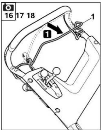
- Remove screw (1) together with washer (2).
- Lift handlebar until recess (3) is above bore (4) in the housing.
- Install screw (1) with washer (2) firmly enough that the handlebar is securely fixed in the service position.
- Lift up the machine at the front, open the discharge flap and fold down the handlebar to the rear. Check that the machine is stable.
After cleaning, set the machine on all four wheels, return the handlebar to the working position and set the desired cutting height.
11.2 Wheels
The wheel bearings are maintenance-free.
11.3 Engine
Maintenance interval: See engine instruction manual
To achieve a long service life, it is always particularly important to maintain a sufficient level of oil and to change the oil and air filter regularly, as well as to observe the recommended oil change intervals.
Information regarding engine oil and oil capacity can also be found in the engine instruction manual.
The cooling ribs must always be kept clean to ensure that the engine is adequately cooled.
11.4 Gearbox
MB 756.0 YS, MB 756.0 YC:
Maintenance interval: Every 1000 operating hours/ at least once a year
The hydrostatic gearbox must only be maintained by trained personnel. VIKING recommends VIKING specialist dealers.
MB 756.0 GS:
The 3-speed gearbox is maintenance-free.
11.5 Blade brake clutch maintenance
Maintenance interval: Once a year
The blade brake clutch is subject to natural wear.
It may only be maintained by trained personnel. VIKING recommends VIKING specialist dealers.
11.6 Checking blade wear
Maintenance interval: Before each use


Risk of injury!
Blades are subjected to differing degrees of wear depending on the location and duration of use. If you use the machine on sandy ground or use it frequently under dry conditions, the blade will be subjected to greater loads and will wear more quickly than the average.
A worn blade may break off and cause serious injuries. The instructions for blade maintenance must therefore always be observed.
Checking procedure

Risk of injury!
Observe the safety instructions in the "For your safety" section.
(⇒ 4.7)
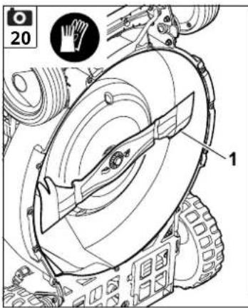
- Place the machine in the cleaning position. (⇒ 11.1)
- Clean mowing blade (1) and check for notches and cracks.
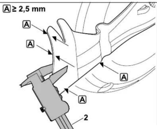
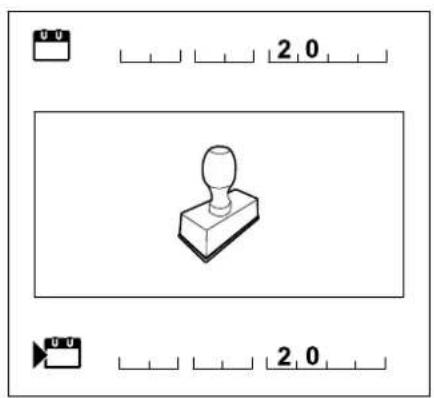
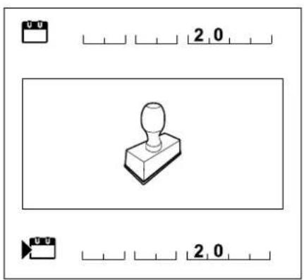
- Use slide calliper (2) to measure the blade thickness A at several points.
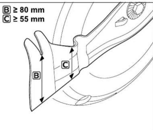
- Measure the blade width as illustrated at the points B and C on the left and right of the blade.
Wear limits:
The blade thickness Ⓐ must be at least 2,5 mm at any point.
The blade width must be at least 80 mm at point B and at least 55 mm at point C.
Different wear limits apply if e.g. the mulching blade available as a special accessory is installed in the lawn mower instead of the supplied mowing blade.
11.7 Removing and installing the mowing blade


Risk of injury!
Always wear gloves.

Removing
- Place the machine in the cleaning position. ( 11.1)
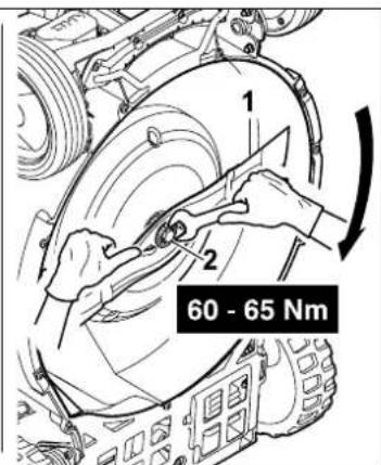
- Hold mowing blade (1) and loosen blade fastening screw (2).
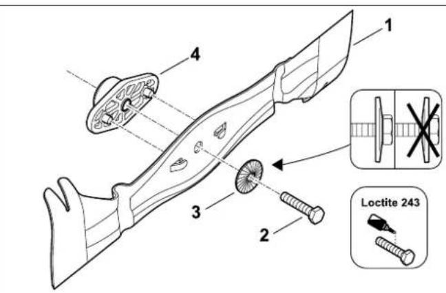
- Remove blade fastening screw (2), retaining washer (3) and mowing blade (1).
Assembly

Avoid damage to the machine!
The mowing blade must be replaced if notches or cracks are detected or if a wear limit is reached ( 11.6).
- Clean the blade contact surface and blade holder.
- Secure the blade fastening screw with Loctite 243.
- Place mowing blade (1) on blade holder (4) as illustrated.
- Position retaining washer (3) as illustrated and tighten with blade fastening screw (2) to 60 - 65 Nm.

Risk of injury!
The prescribed tightening torque must be observed.
Retaining washer (3) must be replaced each time the blade is installed.
Blade fastening screw (2) must be renewed each time the blade is replaced.
11.8 Sharpening the mowing blade
If mowing results deteriorate over time, this is usually the result of a blunt mowing blade.
The following points must be noted when resharpening:
- Remove the mowing blade. (⇒ 11.7)
- Cool the mowing blade when sharpening, e.g. with water. The blade must not be allowed to display blue colouring, as this would reduce its cutting quality.
- Sharpen blades evenly to prevent vibration due to imbalance.
- The cutting angle of 30^ must be observed.
- Observe the wear limits when sharpening.
- Remove any sharpening burr.
11.9 Maintaining cables
The cables are adjusted correctly at the factory.
The throttle cable and the blade brake clutch cable must only be maintained by trained personnel. VIKING recommends VIKING specialist dealers.
After prolonged use or under certain conditions, it can be necessary to adjust the self-propulsion cables.
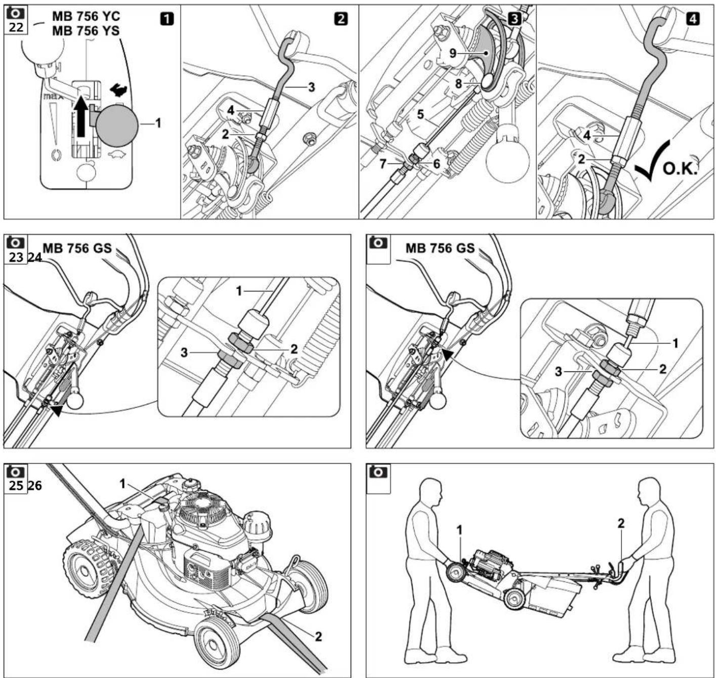
Adjusting the hydro self-propulsion cable
MB 756.0 YS, MB 756.0 YC
Maintenance interval: As required
Adjustment of the cable can be necessary
- if the maximum driving speed is no longer achieved over time.
- if self-propulsion is permanently engaged. This means that the lawn mower automatically begins to move when the recoil starter rope is pulled, despite the self-propulsion lever not being actuated.
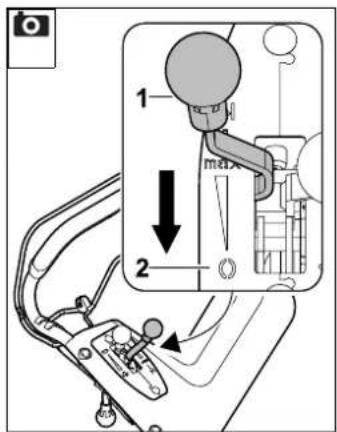
Adjusting the cable
- Push driving speed lever (1) fully forwards.
- 2Loosen lock nut (2), loosen shift linking (3) by turning adjustment nuts (4).
- 3Adjust cable (5) using the two nuts (6, 7).
When correctly adjusted, the cable is tensioned slightly and pin (8) is positioned right at the bottom of guide (9). The machine can be pulled back – the wheels are not blocked during this process.
- 4 Adjust the shift linkage without play using adjustment nuts (4), then tighten lock nut (2) again.
Adjusting the gearshift cable
MB 756.0 GS
Maintenance interval:
As required

Adjustment of the cable is necessary
- if, following lengthy use, the individual gears can no longer be engaged.
Adjusting the cable
- Tension cable (1) using the two nuts (2, 3) on the underside of the handlebar so that all three gears can be correctly engaged.
Adjusting the self-propulsion cable
MB 756.0 GS

Maintenance interval: As required
Adjustment of the cable is necessary
- if, after a lengthy period of use, self-propulsion does not engage when the self-propulsion lever is actuated.
- if self-propulsion is permanently engaged. This means that the lawn mower automatically begins to move when the recoil starter rope is pulled, despite the self-propulsion lever not being actuated.

Risk of injury!
The self-propulsion cable must be correctly adjusted before the machine is operated.
Checking the cable tension:
- Engage 3rd gear and pull the recoil starter rope – the lawn mower is not driven.
- Pull the self-propulsion lever to the handlebar and hold, pull the recoil starter rope - the lawn mower is driven.
Adjusting the cable:
- Tension cable (1) using the two nuts (2, 3) on the underside of the handlebar so that self-propulsion begins when the self-propulsion lever reaches approx. half its travel.
11.10 Storage and periods of inoperation (winter break)
Store the machine in a dry, locked, dust-free place. Make sure that it is out of the reach of children.
Any faults must be remedied prior to storage. The machine must always be in a safe operating condition.
Empty the fuel tank and carburettor prior to storage (e.g. by running empty).
Also note the following points when storing the machine for long periods (winter break):
- Clean all external parts of the machine with care.
- Thoroughly lubricate/grease all moving parts.
- Unscrew the spark plug (see engine instruction manual) and pour approx. 3 cm³ of engine oil into the engine via the spark plug hole. Turn the engine several times with the spark plug removed (pull the recoil starter rope).

Fire hazard!
Keep the spark plug socket away from the spark plug hole due to the danger of ignition.
- Screw the spark plug back in (see engine instruction manual).
- Perform an oil change (see engine instruction manual).
- Cover the engine and store the machine in the normal position.
12. Transport

Risk of injury!
Before transporting, carefully read and observe the section "For your safety", in particular the "Transporting the machine" section. ( 4.4)
12.1 Securing the machine (lashing)

Only transport the machine on all four wheels, on a clean, level load floor.
- Secure the machine against slipping using suitable fastening materials. Attach ropes or straps to lower handlebar (1) and bumper (2).
12.2 Lifting or carrying the machine

Always lift or carry the lawn mower with two people.
- Hold the lawn mower at carrying handle (1) and at handlebar (2) and lift.
13. Environmental protection
Lawn clippings should be composted and not disposed of in household waste.
The machine, its packaging and accessories are all produced
from recyclable materials and must be disposed of accordingly.
By disposing of materials separately, and in an environmentally friendly manner, valuable resources can be re-used. For this reason, the machine should be disposed of for recycling at the end of its useful life. Pay particular attention to the information in the "Disposal" section during disposal ( 4.9).
Consult your recycling centre or your specialist dealer for information on the proper disposal of waste products.
14. Minimising wear and preventing damage
Important information on maintenance and care of the product group
Petrol lawn mowers
VIKING assumes no liability for material or personal damage caused by the non-observance of information contained in the operating instructions, in particular with regard to safety, operation and maintenance, or which arise through the use of unauthorised attachment or spare parts.
Please always observe the following important information for the prevention of damage or excessive wear to your VIKING machine:
1. Wearing parts
Some parts of the VIKING machine are subject to normal wear even when used properly and must be replaced in due time depending on type and duration of use.
These include:
- Mowing blade
- Grass catcher bag
- V - b e l t
- Skirting protectors
- Tyres
- Mowing channel insert
The VIKING machine must be used, maintained and stored with the care described in this instruction manual. Any damage caused by non-compliance with the safety, operating and maintenance instructions is the sole responsibility of the user.
This applies in particular to:
– Product modifications not approved by VIKING.
– Use of fuel and lubricants not approved by VIKING (lubricants, petrol and engine oil, see engine manufacturer's specifications).
- The use of tools or accessories which are not approved or suitable for the machine, or are of inferior quality.
- Improper use of the product.
– Use of the product for sporting or competitive events.
- Resultant damage due to continued use of the product with defective components.
3. Maintenance operations
All operations listed in the section "Maintenance" must be performed regularly.
If these maintenance operations cannot be carried out by the user, a specialist dealer must be commissioned to perform them.
VIKING recommends that you have maintenance operations and repairs performed exclusively by a VIKING specialist dealer.
VIKING specialist dealers regularly attend training courses and are provided with technical information.
If these operations are neglected, faults may arise which are the responsibility of the user.
These include:
- Corrosive and other resultant damage caused by incorrect storage.
– Damage to the machine through the use of inferior-quality spare parts.
– Damage due to untimely or inadequate maintenance or damage due to maintenance or repair work not performed in the workshops of specialist dealers.
15. Standard spare parts
Mowing blade
6378 702 0100
Blade fastening screw
9008 319 2460
Retaining washer
0000 702 6600

The fastening elements for the mowing blade (blade fastening screw, retaining washer) must be renewed when replacing the blade, i.e. when installing the blade. Spare parts are available from a VIKING specialist dealer.
We,
VIKING GmbH
Hans Peter Stihl-Strasse 5
declare that the machine,
manually operated lawn mower with combustion engine (MB)
manufacturer's VIKING
brand:
type: MB 756.0 GS
MB 756.0 YS
MB 756.0 YC
serial number: 6378
conforms to the following EC directives: 97/68/EC, 2000/14/EC, 2004/108/EC, 2006/42/EC
The product has been developed in conformance with the following standards: EN ISO 5395-1, EN ISO 5395-2
Applicable conformity assessment procedure:
Appendix VIII (2000/14/EC)
Name and address of relevant, named location:
Compilation and storage of technical documentation:
Johann Weiglhofer
VIKING GmbH
The year of manufacture and serial number appear on the identification plate of the machine.
Measured sound power level:
MB 756.0 GS 97,4 dB(A)
MB 756.0 YS 97,4 dB(A)
MB 756.0 YC 97,4 dB(A)
Guaranteed sound power level:
MB 756.0 GS 98 dB(A)
MB 756.0 YS 98 dB(A)
MB 756.0 YC 98 dB(A)
Langkampfen,
2015-01-02 (YYYY-MM-DD)
VIKING GmbH

Weiglhofer
Research and Product Development Manager
17. Technical specifications
MB 756.0 GS/MB 756.0 YS/MB 756.0 YC
Serial number 6378
Engine, design 4-stroke com-
bustion engine
Manufacturer Kawasaki
FJ 180 V KAI
Type
OHV
Displacement 179 ccm
Housing material Die-cast
magnesium
Nominal output at
2,9 - 2800
nominal speed
kW - rpm
MB 756.0 GS/MB 756.0 YS/MB 756.0 YC
Fuel tank 3 l
Starter Rope start
Cutting tool Cutter bar
Cutting width 54 cm
Cutter bar speed 2800 rpm
Cutter bar drive
BBC
Tightening torque for
blade fastening
screw 60 - 65 Nm
Wheel diameter
(front) 207 mm
Wheel diameter
(rear) 232 mm
Grass catcher bag
capacity 80 l
Cutting height 25 - 90 mm
Specified vibration characteristic in
accordance with EN 12096:
Measured value a_hw 2,40 m/sec ^2
Uncertainty K_hw : 1,20 m/sec ^2
Measurement in accordance with EN 20643
In accordance with
Directive
2000/14/EC:
Guaranteed sound
power level L_WAd 98 dB(A)
In accordance with
Directive
2006/42/EC:
Sound pressure level
at workplace L_pA 86 dB(A)
Uncertainty K_pA 2 dB(A)
L/W/H 176/59/116 cm
MB 756.0 YC
Self-propulsion, rear
wheels
Hydrostatic
gearbox, infi-
nitely variable
MB 756.0 YC
Weight
60 kg
MB 756.0 YS
Self-propulsion, rear
Hydrostatic
wheels
gearbox, infi-
nitely variable
Weight
59 kg
MB 756.0 GS
Self-propulsion, rear
3 V (3-speed)
wheels
59 kg
18. Troubleshooting
✗ If necessary, contact a specialist dealer; VIKING recommends VIKING specialist dealers.

See engine instruction manual.
Fault:
Engine does not start
Possible cause:
– Throttle lever set to Stop position
- Choke is not actuated
- No fuel in tank
– Inferior, dirty or old fuel in tank
- Insufficient flow of fuel
- Spark plug dirty or damaged
- Incorrect electrode gap
- Spark plug socket detached from the spark plug
– Engine is flooded due to several starting attempts
– Dirty air filter
– Throttle cable is damaged (e.g. kinked)
Remedy:
- Set throttle lever to the Choke or Start position ( 10.1)
- Set throttle lever to the Choke position (⇒ 10.1)
- Refill fuel tank ( 7.5)
- Clean fuel system and carburettor; always use fresh, good quality fuel ☐, ✗, (⇒ 7.5)
- Check fuel line ☐, ✗
– Clean or replace spark plug
- Adjust electrode gap ✗
- Connect spark plug socket; check connection between ignition lead and socket ✗
- Remove spark plug and dry; set throttle lever to STOP position and pull recoil starter rope several times with spark plug removed; screw in spark plug and connect spark plug socket 📄
- Clean/replace air filter
- Repair throttle cable ✗
Fault:
Starting problems or deteriorating engine power
Possible cause:
- Mowing at an excessively low cutting height or fast speed
– Water in fuel tank and carburettor; carburettor blocked
– Fuel tank contaminated
– Air filter dirty
- Spark plug dirty
Remedy:
- Adapt cutting height and reduce mowing speed
- Empty fuel tank, clean fuel line and carburettor ✗
- Clean fuel tank ✗
- Clean/replace air filter 📄, ✕
- Clean spark plug ✗
Fault:
Engine cuts out during operation
Possible cause:
- Fuel cock closed
- Tank ventilation screw closed
- Blade brake clutch overloaded
Remedy:
- Open the fuel cock (⇒ 10.1)
- Open the tank ventilation screw
(⇒ 10.1)
- Clean the mowing channel, empty the grass catcher bag ( 9.)
Fault:
No drive when self-propulsion lever is actuated
Possible cause:
– Self-propulsion cable incorrectly adjusted
– Self-propulsion cable damaged (e.g. kinked)
- V-belt worn
Remedy:
- Check the adjustment ( 11.9)
- Replace the cable ✗
- Replace the V-belt ✗
Fault:
Engine overheating
Possible cause:
– Oil level in engine too low
– Cooling ribs dirty
Remedy:
- Perform an engine oil change if necessary
– Clean cooling ribs ( 11.3)
Fault:
Poor cut, lawn turning yellow
Possible cause:
– Mowing blade is blunt or worn,
– Rate of feed is too high in relation to the cutting height
- Engine speed is too low
Remedy:
- Re-sharpen or replace mowing blade
(⇒ 11.6)
- Reduce rate of feed and/or select correct cutting height ( 9.), ( 7.3)
- Set the throttle lever to the Start position ( 10.1)
Fault:
Mowing channel blocked
Possible cause:
- Mowing blade is worn
- Mowing grass which is too long or too wet
- Engine speed is too low
Remedy:
- Replace the mowing blade (⇒ 11.6)
- Adapt the cutting height and mowing speed to the mowing conditions ( 9.), ( 7.3)
- Set the throttle lever to the Start position ( 10.1)
Fault:
Excessive vibration during operation
Possible cause:
– Cutting unit defective
- Mowing blade imbalance
- Engine mounting loose
Remedy:
- Check mowing blade, blade shaft and blade fastening screws; tighten blade fastening screws ( 11.7)
– Re-sharpen/replace mowing blade
(⇒ 11.8)
- Tighten engine mounting bolts ✿
Fault:
Petrol runs out of the tank cap when the machine is placed in the cleaning position
Possible cause:
– Tank ventilation screw was tightening too firmly
Remedy:
- Replace tank cap ✗
19. Service schedule
19.1 Handover confirmation
Model: ____
Serial number:

Date: ____ ____ ____ ____ ____ ____
natural_image
Simple line drawing of a mechanical component with a cylindrical top and rectangular base (no text or symbols)
Next service
Date: ____ ____ ____ ____ ____
19.2 Service confirmation
Please hand this instruction manual to your VIKING specialist dealer in the case of maintenance work. He will confirm the service operations performed in the pre-printed boxes.
Service performed on
Next service date

Chère cliente, cher client,
MB 756.0 GS, MB 756.0 YS :
MB 756.0 YC, MB 756.0 YS

MB 756.0 YS 98 dB(A)
MB 756.0 YC 98 dB(A)
Langkampfen,
2015-01-02 (AAAA-MM-JJ)
VIKING GmbH

Weiglhofer
natural_image
Simple line drawing of a mechanical component with a cylindrical top and rectangular base (no text or symbols)
Prochain entretien
Date: ____ ____ ____ ____ ____
Start de verbrandingsmotor, koppel de maaimessen in.
Maaiimes loskoppelen.
MB 756.0 YC, MB 756.0 YS

MB 756.0 YS 98 dB(A)
MB 756.0 YC 98 dB(A)
Langkampfen,
2015-01-02 (JJJJ-MM-DD)
VIKING GmbH

natural_image
Simple line drawing of a mechanical component with a cylindrical top and rectangular base (no text or symbols)
MB 756.0 YC, MB 756.0 YS

MB 756.0 YS 98 dB(A)
MB 756.0 YC 98 dB(A)
Langkampfen,
2015-01-02 (AAAA-MM-GG)
VIKING GmbH

Lu./La./A. 176/59/116 cm
MB 756.0 YC
natural_image
Simple line drawing of a mechanical component with a cylindrical top and rectangular base (no text or symbols)
Prossima revisione
Data: ____ ____ ____ ____ ____
MB 756.0 YC, MB 756.0 YS

97/68/EC, 2000/14/EC, 2004/108/EC, 2006/42/EC
MB 756.0 YS 98 dB(A)
MB 756.0 YC 98 dB(A)
Langkampfen,
2015-01-02 (AAAA-MM-DD)
VIKING GmbH

Weiglhofer
L/Ancho/H 176/59/116 cm
MB 756.0 YC
Tracción trasera
natural_image
Simple line drawing of a mechanical component with a cylindrical top and rectangular base (no text or symbols)
MB 756.0 YC, MB 756.0 YS

97/68/EC, 2000/14/EC, 2004/108/EC, 2006/42/EC
MB 756.0 YS 98 dB(A)
MB 756.0 YC 98 dB(A)
Langkampfen, Áustria,
2015-01-02 (AAAA-MM-DD)
VIKING GmbH

Weiglhofer
natural_image
Simple line drawing of a mechanical component with a cylindrical top and rectangular base (no text or symbols)
MB 756.0 YC, MB 756.0 YS

97/68/EC, 2000/14/EC, 2004/108/EC, 2006/42/EC
MB 756.0 YS 98 dB(A)
MB 756.0 YC 98 dB(A)
Langkampfen,
2015-01-02 (RRRR-MM-DD)
VIKING GmbH

natural_image
Simple line drawing of a mechanical component with a cylindrical top and rectangular base (no text or symbols)
Następny przegląd
Data:
MB 756.0 YC, MB 756.0 YS
MB 756.0 YS 98 dB(A)
MB 756.0 YC 98 dB(A)
Langkampfen,
2015-01-02 (ÉÉÉÉ-HH-NN)
VIKING GmbH

Weiglhofer
MB 756.0 YC, MB 756.0 YS

natural_image
Simple line drawing of a mechanical component with a cylindrical top and rectangular base (no text or symbols)
Следующий техосмотр

MB 756 GS, MB 756 YC, MB 756 YS
VIKING®

natural_image
Product lineup of five lawn lawn tools including lawn maw, grass lawn, and tiller (no visible text or labels)
natural_image
Two lawn mower machines shown side by side, no visible text or symbols
B
INT 1

0478 111 9925 B