USER MANUAL MR 4082 K VIKING
natural_image
Exterior view of a modern cleaning or cleaning utility vehicle (no visible text or symbols)
MR 4082.0 MR 4082.0 K
A
EUR 1
www.viking-garden.com


Achtung!
Anhalten:
natural_image
Technical line drawing of a mechanical component with labeled parts (no text or symbols)
natural_image
Technical line drawing of a mechanical component with a lever and pin (no text or symbols)
natural_image
Line drawing of a truck's side view showing a lift, exhaust pipe, and wheel assembly (no text or symbols)
natural_image
Illustration of a hand pressing down on a curved mechanical component with an arrow indicating motion (no text or symbols)
natural_image
Technical line drawing of a mechanical component with no visible text or symbols
natural_image
Mechanical assembly diagram showing a lever mechanism with pulleys and rotating parts (no text or symbols)
natural_image
Illustration of a hand pressing down on a curved mechanical component with an arrow indicating motion (no text or symbols)
natural_image
Line drawing of a person pushing a vehicle with a directional arrow (no text or symbols)
natural_image
Line drawing of a person pushing a large mechanical component next to a vehicle (no text or symbols)
Schritt 1:
Schritt 1:
natural_image
Technical line drawing of a mechanical device with internal components and a directional arrow indicating motion (no text or symbols)
natural_image
Technical line drawing of a mechanical device with internal components and an arrow indicating motion (no text or symbols)
Schritt 1:
Schritt 4:
natural_image
Technical line drawing of a mechanical component with labeled parts (no text or symbols present)
Der Abstand A = 10 mm.
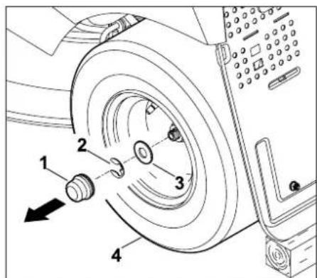
13.9 Räder wechseln
Vorderachse: A = mindestens 200 mm
Hinterachse: B = mindestens 120 mm
Rad demontieren
natural_image
Technical diagram of a vehicle's internal components, showing parts like dashboard and engine compartment (no text or labels)
natural_image
Technical line drawing of a mechanical assembly with no visible text or symbols
natural_image
Diagram of a mechanical component with concentric curved lines and a labeled arrow pointing to a cylindrical feature (no text or symbols present)
natural_image
Technical line drawing of a mechanical component with two mounting holes and an arrow indicating direction (no text or symbols)
2000/14/EC, 97/68/EC, 2004/108/EC,
2006/66/EC, 2006/42/EC
MR 4082.0 K 99,0 dB(A)
Motor, Bauart: 4-Takt-
Verbrennungs-
motor
Kraftstofftank 6 l

| A = | 8 7 c |
| B = | 9 0 c |
| C = 113 cm |
| D = 177 cm |
| E = 213 cm |
| F = 110 cm |
| G = 118 cm |
m
m
21. Fehlersuche
natural_image
Simple line drawing of a mechanical component with a cylindrical top and rectangular base (no text or symbols)
Nächster Service

Thank you for choosing a VIKING quality product.
This product has been produced using state-of-the-art production methods and extensive quality assurance procedures, because our goal is only achieved if you, the customer, are satisfied with your machine.
If you have any questions concerning your machine, please contact your dealer or our sales agency directly.
I hope that your VIKING machine will give you great enjoyment.

Dr. Peter Pretzsch
Management
1. Table of contents
Notes on the instruction manual 68
General 68
Instructions for reading the
instruction manual 68
Machine overview 70
For your safety 71
General 71
Training – learning to use the machine 72
Transporting the ride-on mower 72
Refilling the tank – handling petrol 73
Clothing and equipment 73
Before operation 73
Working with your machine 74
Maintenance and repairs 77
Storage for prolonged periods without operation 78
Disposal 78
Description of symbols 79
Standard equipment 80
Operations prior to initial use 80
Controls 81
Ignition lock 81
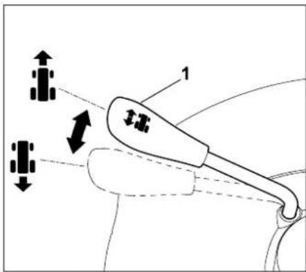
Throttle lever with choke function 81
Mowing deck switch 82
Driving direction selector lever 82
Steering wheel 82
Driver's seat adjustment lever 83
Drive pedal 83
Brake pedal 83
Parking brake 84
Cutting height adjustment lever 84
Grass catcher box emptying lever 85
Grass catcher box release lever 85
Gearbox freewheel lever 86
Level sensor (grass catcher box) 86
Notes on working with the machine 87
Safety devices 88
Operating the machine 88
Filling the fuel tank 88
Starting the engine 89
Stopping the engine 89
Driving 90
Braking 90
Adjusting the cutting height 90
Mowing 91
Emptying the grass catcher box 91
Removing and attaching the grass catcher box 92
Pulling loads 93
Operating on slopes 94
Guide 94
Mowing deck 95
Removing the mowing deck 95
Installing the mowing deck 97
Maintenance 100
Maintenance schedule 100
Lubrication 101
Removing the discharge chute 101
Installing the discharge chute 102
Cleaning the level sensor (grass catcher box) 102
Checking the safety devices 103
Mowing blade maintenance 103
Checking the installation position of the mowing deck 106
Changing the wheels 106
Engine cover 107
Checking the engine oil filling level 110
Changing the engine oil 110
Topping up engine oil 111
Fuel cock 111
Removing steering column cover 112
Installing steering column cover 112
Fuses 112
Battery 113
Cleaning the machine 115
Combustion engine 115
Gearbox 116
Storage 116
Extended periods of inoperation (e.g. winter break) 116
Following storage for extended periods (e.g. over winter) 116
Tyre pressure 116
Opening and closing storage compartment 117
Transport 117
Standard spare parts 118
Accessories 118
Environmental protection 119
Minimising wear and preventing damage 119
CE - manufacturer's declaration of conformity 120
Technical specifications 121
Dimensions 122
Troubleshooting 123
Service schedule 125
Handover confirmation 125
Service confirmation 125
2. Notes on the instruction manual
2.1 General
This instruction manual constitutes original manufacturer's instructions in the sense of EC Directive 2006/42/EC.
VIKING is continually striving to further develop its range of products; we therefore reserve the right to make alterations to the form, technical specifications and equipment level of our standard equipment.
For this reason, the information and illustrations in this manual are subject to alterations.
2.2 Instructions for reading the instruction manual
Illustrations and texts describe specific operating steps.
All symbols which are affixed to the machine are explained in this instruction manual.
Viewing direction:
Viewing direction when "left" and "right" are used in the instruction manual: the user is standing behind the machine and is looking forwards in the direction of travel.
Section reference:
References to relevant sections and subsections for further descriptions are made using arrows. The following example shows a reference to a section: ( 2.1)
Designation of text passages:
The instructions described can be identified as in the following examples.
Operating steps which require intervention on the part of the user:
- Release bolt (1) using a screwdriver, operate lever (2)...
General lists:
– Use of the product for sporting or competitive events
Texts with added significance:
Text passages with added significance are identified using the symbols described below in order to especially emphasise them in the instruction manual:

Danger
Risk of accident and severe injury to persons. A certain type of behaviour is necessary or must be avoided.

Warning
Risk of injury to persons. A certain type of behaviour prevents possible or probable injuries.

Caution
Minor injuries or material damage can be prevented by a certain type of behaviour.

Note
Information for better use of the machine and in order to avoid possible operating errors.
Illustrations with text passages:
Operating steps relating directly to the illustration can be found immediately after the illustration, with a corresponding reference to the item numbers.
Example:
Insert ignition key (1) in ignition lock (2).
Texts relating to illustrations:
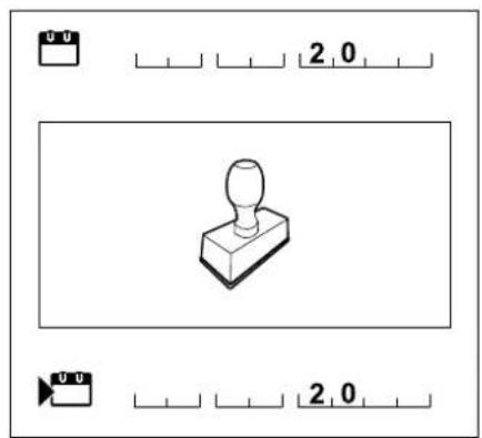
Illustrations relating to use of the machine can be found in the front of this instruction manual.
The camera symbol serves to link the figures on the illustration pages with the corresponding text passages in the instruction manual.

3. Machine overview
natural_image
Technical line drawing of a mechanical component with no visible text or symbols
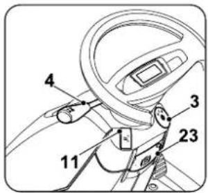
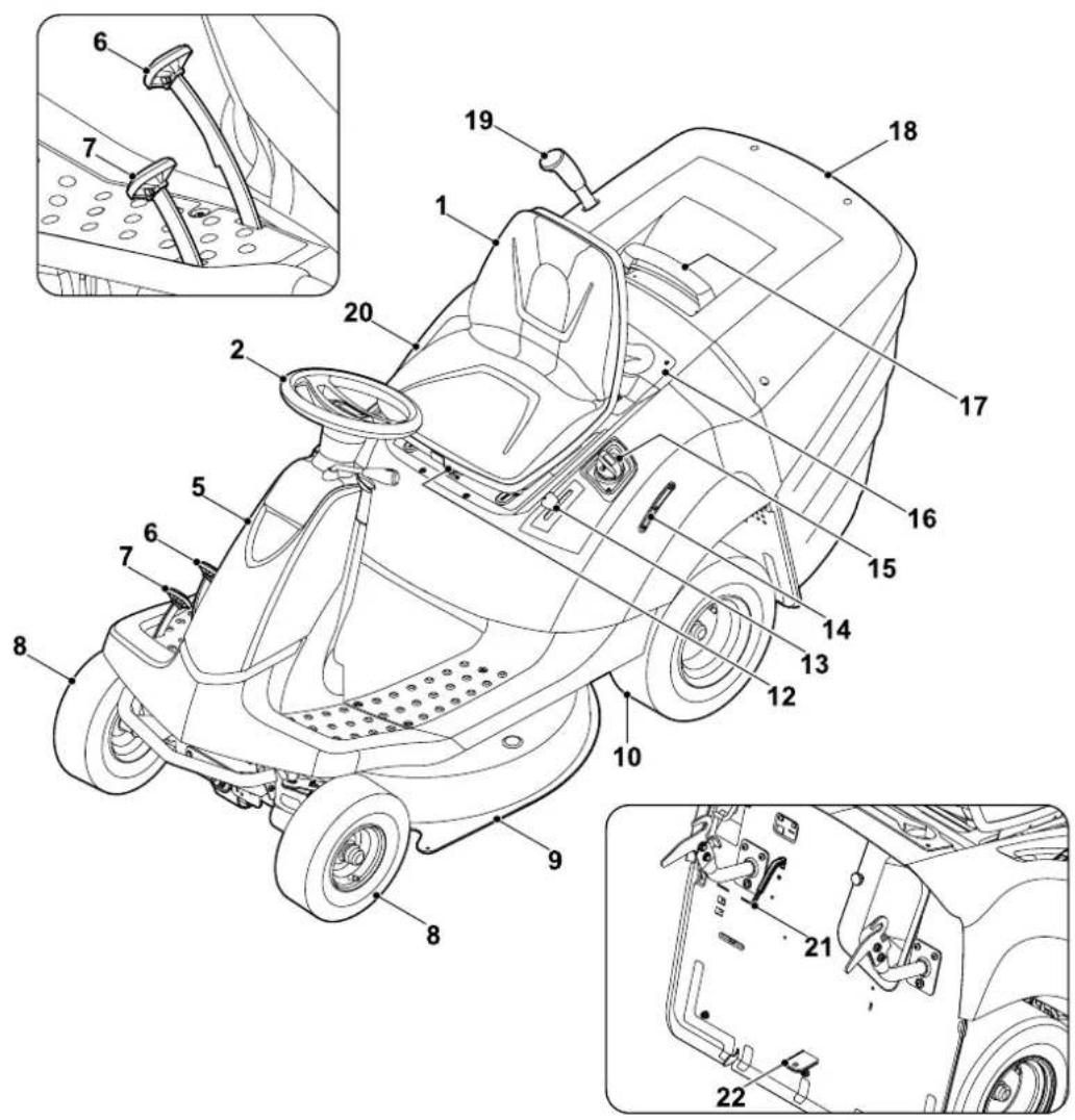
1 Driver's seat
2 Steering wheel
3 Ignition lock
4 Driving direction selector lever (forward / reverse)
5 Cover (steering column)
6 Brake pedal
7 Drive pedal (driving speed)
8 Front wheel
9 Mowing deck
10 Rear wheel
11 Mowing deck switch
12 Driver's seat adjustment lever
13 Throttle lever with choke function
14 Tank display
15 Tank cap
16 Storage compartment
17 Grass catcher box handle with grass catcher box release lever
18 Grass catcher box
19 Grass catcher box emptying lever
20 Cutting height adjustment lever
21 Level sensor
22 Trailer hitch
23 Parking brake
4. For your safety
4.1 General

These safety regulations must be observed when working with the machine.

Read the entire instruction manual before using the machine for the first time. Keep the instruction manual in a safe
place for future reference.
Observe the operating and maintenance instructions contained in the separate engine instruction manual.
These safety precautions are essential for your safety, however the list is not exhaustive. Always use the machine in a reasonable and responsible manner and be aware that the user is responsible for accidents involving third parties or their property.
Only give or lend the machine, including any accessories, to persons who are familiar with this model and how to operate it. The instruction manual forms part of the machine and must always be provided to persons borrowing it.
Never allow children under the age of 16 to use the machine. Local regulations may specify a minimum age for users.
This machine is not suitable for use by persons (in particular children) with impaired physical, sensory or mental faculties or those lacking the appropriate experience and/or knowledge, unless supervised by a person responsible for their safety or having received instructions on use of the machine from such person.
Children must be supervised, in order to ensure that they do not play with the machine.
The machine must only be operated by persons who are well rested and in good physical and mental condition. If your health is impaired, you should consult your doctor to determine whether working with the machine is possible. The machine should not be operated after the consumption of alcohol, drugs or medications which impair reactions.
Caution – risk of accident:
The ride-on mower is only intended for mowing lawns; its use for other purposes is not permitted.
The machine must only be equipped with original VIKING accessories. These enable further applications. Information is available from your VIKING specialist dealer.
Due to the physical danger to the user or other persons, the machine must not be used, for example, for the following applications (incomplete list):
– for cutting creepers,
– for shredding or chopping tree or hedge cuttings,
– for clearing paths (vacuuming, blowing),
– for snow clearing using the mowing deck,
– for the care of lawn roofs,
– for levelling earth mounds, e.g. mole hills.
– for transporting clippings, except in the grass catcher box intended for this purpose.
The machine is not approved for use on public roads.
The carrying of persons (especially children) and animals is not permitted.
Objects must not be transported on the machine, but only with the aid of a trailer approved by VIKING (accessory). The weight limits must be observed. ( 11.10)
Particular care is required during use in public green spaces, parks, sports fields, along roads and in agricultural and forestry businesses.
The machine must not be used for sporting or competitive events.
For safety reasons, any modification to the machine, except the proper installation of accessories or attachments approved by VIKING is forbidden and results in voiding of the warranty cover. Information regarding approved accessories and attachments can be obtained from your VIKING specialist dealer.
In particular, any tampering with the machine which increases the power output, engine speed or driving speed is forbidden.

Caution: Danger to health due to vibrations!
Excessive exposure to
vibrations can result in damage
to the cardiovascular or nervous system, particularly in persons with cardiovascular problems. Please consult a physician if you experience symptoms that may have been caused by vibrational loads.
Symptoms of this kind principally affect the fingers, hands or wrists and include (incomplete list):
- numbness,
- pain,
- muscular weakness,
- skin discolouration,
– unpleasant tingling sensation.
4.2 Training – learning to use the machine
Make sure that you are familiar with the controls and operation of the machine. In particular, the user must know how the work tools and engine can be stopped quickly.
The machine must only be used by persons who have read the instruction manual and are familiar with operation of the machine. The user should seek expert and practical instruction prior to initial operation. The user must receive instruction on safe use of the machine from the vendor or another expert.
During this instruction, the user should be made aware
– that the utmost care and concentration are required for working with the machine.
– that a ride-on mower which is sliding down a slope cannot be brought under control by applying the brake.
The main causes for the loss of control over the ride-on mower include:
- inadequate adhesion of the wheels,
– driving too fast,
– inappropriate braking,
– incorrect use (sport events etc.),
– inadequate knowledge of the effects associated with ground conditions, especially on slopes (see section "For your safety", "Working on slopes"),
– incorrect attachment of loads and poor load distribution.
4.3 Transporting the ride-on mower
On account of its own weight, the ride-on mower can cause severe crush injuries. Particular care must be taken when loading or unloading the ride-on mower onto/from a vehicle or trailer for transport purposes.
This ride-on mower must not be towed. For transporting on public roads, a suitable vehicle or a suitable trailer must be used.
During transport, the ride-on mower must be secured to a load floor as described in this instruction manual. Furthermore, the parking brake must be engaged. ( 14.)
Prior to transporting or storage, disengage the drive to the mowing blade or attachments.
When transporting the machine, always observe regional legislation, especially regarding load security and the transport of objects on load floors.
Allow the machine, in particular the engine and muffler, to cool down completely after loading and before further transport. The load floor and the area around the muffler and engine must be kept free of combustible materials such as straw, leaves or dry grass residues.
4.4 Refilling the tank – handling petrol

Danger to life!
Petrol is poisonous and extremely inflammable.
Petrol must only be stored in appropriate, tested containers (canisters). Always screw on the fuel tank and canister caps properly and tightly. Defective caps must be replaced for safety reasons.

Keep petrol away from sparks, naked flames, pilot lights, heat sources, and other ignition sources. Do not smoke!
Refill the tank out-of-doors and do not smoke during refilling.
Before refilling the tank, stop the engine and allow it to cool.
Refilling with petrol must be performed before the engine is started. When the engine is running or is hot, the tank cap must not be removed and the tank must not be refilled with petrol.
Open the fuel tank cap slowly and carefully. Wait for pressure compensation and only then remove the tank cap completely.
Use a suitable funnel or filling pipe for refilling the tank, so that no fuel can spill onto the engine and housing or the lawn.
Do not fill fuel tank completely, but fill to approx. 4 cm below the edge of the filler neck so that the fuel has room to expand.
If petrol is spilled, the engine must only be started after the petrol-contaminated area has been cleaned. All attempts at starting must be avoided until the petrol fumes have dispersed (wipe dry).
Any spilt fuel must be wiped up immediately.
Clothing must be changed if it comes into contact with petrol.
Following each refilling of the tank, the fuel tank cap must be properly screwed on and tightened. The machine must not be operated without the original tank cap.
For safety reasons, the fuel line, fuel tank, tank cap and connections must be checked regularly for damage, ageing (brittleness), firm seating and leaks. Replace if necessary (consult a specialist dealer; VIKING recommends VIKING specialist dealers).
If it is necessary to drain the tank, this must be done out of doors.
Never use beverage bottles or similar for disposal or storage of fuels and lubricants. Persons, particularly children, could be tempted to drink out of them.
Never store the machine with petrol in the tank inside a building. The resulting petrol fumes could come into contact with naked flames or sparks and could be ignited.
Do not leave the machine and the fuel tank close to heating systems, radiant heaters, welding equipment and other sources of heat. Explosive hazard!
4.5 Clothing and equipment

Always wear sturdy footwear with high-grip soles when working. Never work barefoot
or, for example, in sandals.
Always wear long trousers and tight-fitting clothing when operating the machine.
Never wear loose clothes which may become caught on moving parts (control levers) – do not wear jewellery, ties or scarves.

Also always wear sturdy gloves and tie up and secure long hair (headscarf, cap, etc.) when performing maintenance and
cleaning work or when transporting the machine.

Wear suitable safety glasses when sharpening the mowing blade.
4.6 Before operation
Make sure that only persons who are familiar with the instruction manual are permitted to use the machine.
Carefully inspect the complete area on which the machine is to be used and remove any stones, sticks, wires, bones and other foreign objects which could be thrown up by the machine. Obstacles (e.g. tree stumps, roots) can be easily overlooked in long grass.
For this reason, mark all foreign objects (obstacles) which are hidden in the lawn and cannot be removed before commencing work with the machine.
Observe the local regulations regarding permitted operating times for gardening power tools with combustion engines or electric motors.
Check the fuel system (particularly visible parts such as e.g. tank, tank cap, hose connections) before operating the machine. In the event of any leaks or damage, do not start the engine – fire
hazard!
Have the machine repaired by a specialist dealer prior to operation.
Defective mufflers and all other worn or damaged parts must be removed before use of the machine. Replace any illegible or damaged danger signs and warnings on the machine. Your VIKING specialist has a supply of replacement stickers and all the other spare parts.
Never use the machine with damaged safety devices or with safety devices removed.
The screwed-on discharge port (discharge chute on mowing deck) must always be securely fastened to the mowing deck. It must not be damaged and, if necessary, it must be replaced by a technician.
The braking function must be checked before each use. ( 8.8)
Before each use, check whether:
– the cutting tool and the entire cutting unit (mowing blade, blade clutch, blade brake, retaining pin, mowing deck housing) are in good condition. Particularly check for secure fastening, damage and wear.
– the tank cap is securely attached.
– the tank and fuel-carrying parts, as well as the tank cap are in good condition.
– the safety devices are in good condition and function correctly.
– the tyres (inflation pressure, damage, wear) and frame are in good condition. Check that all screw connections are securely fastened. In particular, all maintenance operations listed in the maintenance schedule under the heading “Before each use” must be carried out. ( 13.1)
If necessary, consult a specialist dealer. VIKING recommends VIKING specialist dealers.
4.7 Working with your machine

Never work in the vicinity of other persons, particularly children, or animals. Ensure that the grass is never
discharged in the direction of other persons.
Do not operate the machine in the rain or during thunder storms, particularly when there is a risk of lightning strike.
Exhaust gases:

Danger to life through poisoning!
In the case of nausea, headache, impaired vision (e.g. decreasing field of view) hearing disorder, dizziness, decreasing power of concentration, stop working immediately. These symptoms may be caused by excessively high exhaust gas concentrations.

The machine generates poisonous exhaust gases when the engine is running. The gases contain poisonous
carbon monoxide, a colourless and odourless gas, as well as other pollutants. The engine must never be operated in closed or poorly ventilated spaces.
The engine exhaust is released into the air in front of the left rear wheel. When working with the machine, ensure that this area is always kept clean and is never covered in order to prevent the accumulation of exhaust gasses.
Starting:
The machine must only be started from the driver's seat.
Start the machine on level ground, not on a slope.
The engine may only be started in a well ventilated working area, sufficient ventilation must be ensured, particularly in garages.
Before starting the engine, disengage the cutting tool, attachments and drive and press down the brake pedal fully.
When starting, it must be ensured that there is sufficient clearance between the feet and the cutting tool.
Never start the engine by short-circuiting the starter terminal. If the normal starter circuit is bypassed, the ride-on mower may suddenly be set in motion.
Never start the engine if the smell of petrol can be detected – Explosive hazard!
Working:

Warning – Risk of injury!
Observe the working area of the mowing blade. Never put hands or feet on or underneath rotating parts. Never touch the rotating mowing blade. Always keep away from the discharge opening. An adequate safety distance must always be maintained.

Only work during the day or with good artificial light.
When driving off the lawn or when not mowing, the mowing blade must be disengaged and the mowing deck must be set to the highest cutting position.
Objects hidden in the grass (lawn sprinkler systems, posts, water valves, foundations, electrical wires, etc.) must be avoided. Never intentionally run over any such foreign objects.
The mowing deck and discharge chute should be removed when working with additional attachments – observe instruction manual for the attachments.
Always hold the steering wheel firmly with both hands when driving.
Particular care must be taken when driving on lawns and other uneven surfaces, as the steering wheel can be made to turn due to holes, mounds, impacts etc.
Risk of injury to hands and fingers!
If, during operation, a defect in the tank, tank cap or in the fuel-carrying components (fuel lines) is detected, the engine must be stopped immediately. A specialist dealer must then be contacted. VIKING recommends VIKING specialist dealers.
Beware of depressions (holes) in the terrain and other invisible points of danger. Obstacles can be easily overlooked in long grass.
Always drive at a reasonable speed.
Particular care must be taken at points of poor visibility, bushes, trees and other obstacles, behind which persons, especially children, or animals may be hidden.
Bring the ride-on mower to a standstill immediately and stop the mowing blade if someone moves into the area to be mown.
Always monitor the area in front of the vehicle. Beware of obstacles, in order to be able to evade them in time.
Before reversing, always check the area behind the ride-on mower and, if present, disengage the attachment. Never mow in reverse, if it is not absolutely necessary. When mowing in reverse, take particular care and before beginning to mow, thoroughly check the entire area behind the ride-on mower.
When working together in a group, always inform the others in advance of what you intend to do. Maintain a safety distance!
The vehicle speed must be reduced before each change of direction, so that the user retains control of the machine at all times and also that the ride-on mower cannot tip over.
When operating near to roads and when crossing roads, other road users must be taken into account.
Take particular care when mowing near roads, cycle paths and footpaths. Objects which are thrown up by the mower can cause severe injury and damage.
Only empty the grass catcher box from the driver's seat.
Before emptying the grass catcher box, always disengage the mowing blade and wait until it has come to a standstill.
When operating the ride-on mower with attachments, always follow the instructions and safety regulations supplied with the attachments.
Switch off the drive, stop the engine and wait until the mowing blade has come to a complete standstill, engage the parking brake and remove the ignition key:
– before remedying blockages, including those in the discharge chute,
— before checking, cleaning or working on the ride-on mower,
- if the mowing blade has hit an obstacle. Inspect the machine and the cutting tool for damage and have any necessary repairs performed before re-starting.
- if the machine begins to vibrate excessively. It must be checked immediately.
- when abandoning or when transporting the machine.
Stop the engine and wait until the mowing blade has come to a complete standstill:
– before filling with fuel,
– before removing the grass catcher box.
Working on slopes:
Slopes are one of the major causes of accidents in which control over the ride-on mower is lost causing it to tip over, which can result in severe or even fatal injuries.
There is no "safe" slope! Driving on grassy slopes requires special concentration.
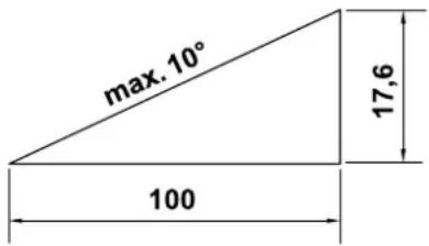
For safety reasons, the machine must not be used on slopes with an inclination of more than 10^ (17.6%). Risk of injury!
A slope inclination of 10^ corresponds to a vertical height increase of 17.6 cm for a 100 cm horizontal distance.
In order to ensure an adequate oil supply for the engine, the information in the accompanying engine instruction manual must be additionally observed when using the machine on slopes.
If you cannot drive up the slope in reverse or if you have doubts regarding safety, you should not drive on the slope.
Starting off or stopping on a gradient must be avoided.
Do not use the machine in places (slopes, ditches, etc.) where the ride-on mower can tip over or slide. The danger of tipping over or sliding increases if the ground is soft or damp.
Slopes must be driven on in a longitudinal direction. Driving transversely increases the danger of tipping over.
Do not change speed or direction abruptly when driving on slopes. Work in this type of situation requires calm, cautious and even operation of the ride-on mower.
Changes of direction on slopes must be avoided. Only turn on slopes if this is unavoidable. If possible, drive slowly and in a large curve in the down-slope direction.
Do not mow wet grass, particularly on slopes, as wheel grip is reduced on wet grass. The ride-on mower could slide and become uncontrollable for the user.
The gearbox must never be disengaged via the gearbox freewheel when driving on slopes.
Special care must be taken when operating attachments on slopes (altered weight distribution of the machine).
If the wheels start to slip or if the vehicle becomes stuck in the up-slope direction when driving on an incline, the mowing blade or the attachment must be disengaged. Then leave the slope by driving slowly downhill in a straight line.
Never try to stabilise the ride-on mower by pressing on the ground with your foot.
The weight of the grass catcher box increases the danger of the ride-on mower tipping over, particularly when it is full.
Never empty or lift the grass catcher box on an incline.
Pulling loads:
Particular care must be taken when pulling loads, in order to prevent the risk of severe or even fatal injuries due to the ride-on mower tipping over.
Only use accessories approved by VIKING for transporting objects. Transportation on the ride-on mower, in or on the grass catcher box, is not permitted.
For pulling loads, use only the trailer hitch. Loads must never be attached to the axle housing or to another point above the trailer hitch.
Please refer to the section "Pulling loads" for information on pulled and coupling loads. ( 11.10)
Exceeding the specified pulled load is dangerous and may result in damage to the machine (engine, gearbox etc.).
When transporting on slopes, the loads must be adapted so that safe handling of the ride-on mower (e.g. braking, change of direction, starting off) is ensured at all times.
Check whether loads are properly and securely fastened. Use lashing straps for securing loads.
Ensure balanced load distribution.
Use suitable additional weights (accessories) if this is described in the instruction manual for the attachment.
Do not execute tight curves. Particular care must be taken when reversing.
Do not change speed or direction abruptly.
Stopping and parking:
The ride-on mower must only be parked on a level surface.
Make sure that the ride-on mower has come to a complete standstill before you dismount.

STOP
Beware of the cutting tool running on for several seconds before coming to a standstill.
Before leaving the driver's seat, disengage the mowing blade or
the drive to the attachments, lower the mowing deck and all attachments, set all control levers to the neutral position, engage the parking brake, stop the engine and remove the ignition key.
Keep the ignition key in a place where only authorised persons can access it.
4.8 Maintenance and repairs

Before beginning cleaning, adjustment, repair and maintenance operations, p the machine on firm, level ground, engage the parking brake, stop the engine, allow it to cool down and remove the ignition key.
Allow the machine to cool down before working on or around the engine, exhaust manifold or muffler; this also applies in particular to all maintenance operations on the mowing deck. Temperatures of 80^ C and above can be reached. Danger of burns:
Cleaning:
Following operation, the entire ride-on mower and the attachments must be cleaned. In particular, all grass residues must be removed because the moisture these contain leads to damage in the long term.
VIKING does not recommend the use of high pressure cleaners. ( 13.19)
Never drive close to an edge or a ditch for the purpose of cleaning (e.g. the frame of) the ride-on mower.
In order to prevent fire hazards, keep the engine, cooling ribs, battery compartment, area around the fuel tank and exhaust free from grass, leaves or escaping oil (or grease).
Always clean the grass catcher box.
Maintenance operations:
Only maintenance operations described in this instruction manual may be carried out. Have all other work performed by a specialist dealer.
If you do not have the necessary expertise or auxiliary equipment, please always contact a specialist dealer.
VIKING recommends that you have maintenance operations and repairs performed exclusively by a VIKING specialist dealer.
VIKING specialist dealers regularly attend training courses and are provided with technical information.
Only use tools, accessories or attachments approved for this machine by VIKING or technically identical parts. Otherwise, there may be a risk of accidents resulting in personal injury or damage to the machine. If you have any questions, please consult a specialist dealer.
The characteristics of original VIKING tools, accessories and spare parts are optimally adapted to the machine and the user's requirements. Genuine VIKING spare parts can be recognised by the VIKING spare parts number, by the VIKING lettering and, if present, by the VIKING spare parts symbol. On smaller parts, only the symbol may be present.
The ride-on mower and all attachments should be inspected once annually by a specialist dealer. ( 13.1)
Always keep warning and information stickers clean and readable. Damaged or missing stickers must be replaced by new, original plates from your VIKING specialist dealer. If a component is replaced with a new component, ensure that the new component is provided with the same stickers.
For safety reasons, fuel-carrying components (fuel line, fuel cock, fuel tank, tank cap, connections, etc.) must be checked regularly for damage and leaks and replaced by a technician if necessary (VIKING recommends VIKING specialist dealers).
Before starting work on or near electrical components, the negative (−) cable must be disconnected from the battery.
The machine is equipped with numerous safety devices. These devices must not be removed or modified (bypassed, etc.) and must be checked at regular intervals. Operations on the safety devices must only be carried out by a technician. VIKING recommends VIKING specialist dealers.
Ensure that all nuts, pins and screws, especially the blade fastening screw, are securely tightened, so that the machine is in a safe operating condition.
For safety reasons, worn or damaged parts must be replaced immediately.
Check the grass catcher unit (e.g. grass catcher box, discharge chute) regularly for wear, damage or loss of functionality.
Particular care is required when working under the machine, due to the weight of the ride-on mower. If necessary, contact a specialist dealer; VIKING recommends VIKING specialist dealers. They will have a workshop pit or a hydraulic working platform.
Check the secure fastening of the front and rear wheels.
Always maintain the ride-on mower and the attachments in perfect operating condition. All safety devices must be present and be in perfect operating condition.
Ensure that the tyres have the correct tyre pressures. The tyre pressures specified in the instruction manual must not be exceeded.
Only perform work on the mowing blades when wearing thick work gloves and exercising extreme care.
Check the function of the brakes at regular, short intervals and, if necessary, have the required adjustments or maintenance operations performed by a technician. VIKING recommends VIKING specialist dealers.
Electrical system and battery:
In order to prevent sparks due to short circuiting, the negative (−) cable must always be disconnected from the battery first and reconnected last.

Never smoke when working on the battery. Sparks, naked flames and other heat sources must be kept away from the
battery.
Particular care is necessary when using battery jump leads. Observe the relevant instructions in order to prevent damage to the ride-on mower (in particular, actuate the starter for a maximum of 10 seconds). ( 11.2)
When charging the battery using another charging system, observe the instructions in section "Charging the battery".
(⇒ 13.18)
Never open the battery and do not drop it.
Always charge the battery in an enclosed, well-ventilated room which is dry and weather-protected.
Do not short circuit the battery connections.
Deformed or faulty (leaking) batteries must not be used and must be replaced and disposed of in an environmentally-friendly manner. Observe country-specific legislation.
Fluid may escape from faulty batteries. Avoid contact! In the case of inadvertent contact, rinse with water. Seek medical attention if the fluid contacts the eyes. Escaping battery fluid can cause skin irritation and burns.
Visually inspect the battery connection cables for damage at regular intervals. Have damaged cables replaced by a technician.
Never bypass the fuses. Never use a fuse with a value that differs from the specified rating (ampere).
4.9 Storage for prolonged periods without operation
Allow the engine to cool before storing the machine in an enclosed space.
Store the ride-on mower with empty fuel tank and the fuel reserve in a lockable and well-ventilated room.
Never store the machine with petrol in the fuel tank inside a building in which the petrol fumes could come into contact with naked flames or sparks.
If the tank has to be emptied (e.g. immobilisation before the winter break), the fuel tank must be emptied out of doors only (empty the tank by running the engine out of doors, for example).
Store the machine in good operational condition.
The ignition key must always be removed and kept in a safe place, to prevent unauthorised or improper use by children or other persons.
Thoroughly clean the ride-on mower before storage (e.g. winter break). Dry grass residues and leaves near to the muffler may ignite. Danger of combustion!
Allow the machine to cool down completely before covering it.
Perform all the necessary maintenance operations (lubrication etc.) before storing the machine. ( 13.1)
The battery cables must be disconnected if the ride-on mower is immobilised for longer periods. VIKING recommends removing the battery and storing it in a dry and locked place. ( 13.18)
Ensure that batteries are protected from unauthorised use (e.g. by children).
4.10 Disposal
Waste products such as used engine oil or fuel, used lubricants, filters, batteries and similar wearing parts can be harmful to people, animals and the environment, and must consequently be disposed of properly.
Consult your recycling centre or your specialist dealer for information on the proper disposal of waste products. VIKING recommends VIKING specialist dealers.
Ensure that old machines are properly disposed of. Render the machine unusable prior to disposal. In order to prevent accidents, ensure that you remove the ignition key, the battery and the ignition lead on the engine.
Risk of injury due to the mowing blade! Always store an old ride-on mower in a safe place prior to scrapping. Ensure that the machine and particularly the mowing blade are kept out of the reach of children.
The battery must be disposed of separately from the machine. Ensure that batteries are disposed of safely and in an environmentally friendly manner.
5. Description of symbols

Caution:
Read and follow the instruction manual and the safety instructions before initial use.
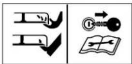
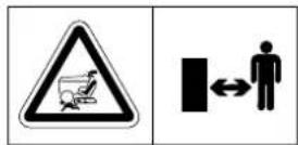
Risk of injury:
Remove the ignition key before performing any work on the cutting tool or maintenance and cleaning work.
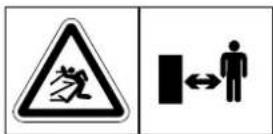
Caution:
Keep a safe distance.
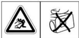
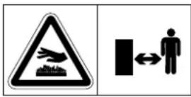
Caution:
Beware of objects being thrown out when the engine is running – work with grass catcher box or deflector (special accessory).
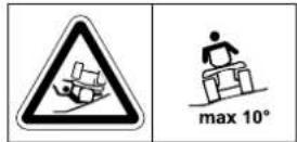
Risk of injury:
Do not drive or mow on slopes with an inclination greater than 10^ (17%).
Danger of tipping over!
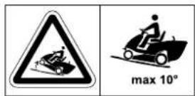
Risk of injury:
Do not drive or mow straight up or down slopes and ramps with an incline greater than 10^ (17%).
Danger of tipping over!
Risk of injury:
Keep other persons out of the danger area.
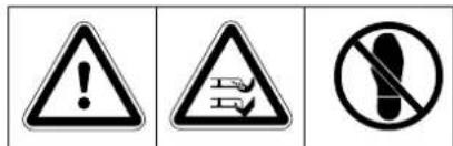
Caution:
Never reach into the working area of the mowing blade when the engine is running.
Risk of injury!
Do not stand on the mowing deck.
Danger of burns!
Do not touch hot surfaces. Engine components, especially mufflers, can become extremely hot.
6. Standard equipment
Designation Qty.
- Basic unit 1
- Ignition key 2
- Grass catcher box 1
– Instruction manual 1
– Engine instruction manual 1
- Supplementary sheet - 1 battery
7. Operations prior to initial use
- Perform engine oil level check.
(⇒ 13.11)
- Fill fuel tank. (⇒ 11.1)
- Open fuel cock. (⇒ 13.14)
- Optimise tyre pressure. (⇒ 13.25)
8. Controls
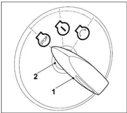
8.1 Ignition lock

Note
The ignition key can only be inserted and removed in the "engine off" (STOP) position. The ignition lock can only be operated with the appropriate ignition key.
Never use a screwdriver or similar!
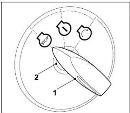
Insert ignition key (1) in ignition lock (2).
The following three positions can be selected by turning the ignition key:
Engine off:
In this position, the engine is not running or will be stopped.
Ignition on or engine running: If the ignition key is moved to this position when the engine is stopped, the ignition is switched on without the engine starting.


Following start-up, the ignition key returns automatically to this position and the engine continues to run.
Starting the engine:
When all safety-relevant points for starting are fulfilled and the ignition key is turned to this position, the engine starts.
On releasing the ignition key, it returns automatically to the "engine running" position.

8.2 Throttle lever with choke function

Note
When starting the machine when the engine is cold, the throttle lever must be set to the choke position.
Avoid damage to the machine. It must always be ensured that the throttle lever is not in the choke-position when the engine is running.
Choke position:

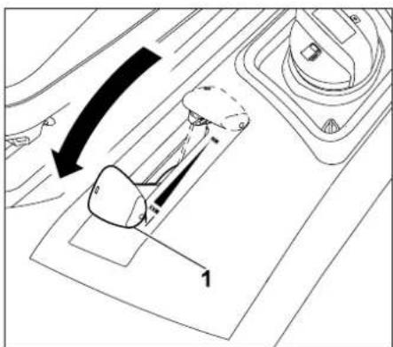
Push throttle lever (1) fully forward into the choke position (note detent).
Adjusting the engine speed:


Note
Only mow at the maximum engine speed.
The throttle lever must be in the MAX position.
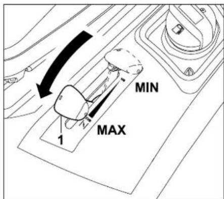
If throttle lever (1) is pushed downwards or upwards, the engine speed changes and, if the mowing deck is engaged, the speed of the mowing blade is changed.
MAX position:
If the throttle lever is moved forward towards the MAX marking, the engine speed is increased.
MIN position:
If the throttle lever is moved back towards the MIN marking, the engine speed is reduced.
8.3 Mowing deck switch
The mowing deck can be engaged with the engine running by pressing the mowing deck button.

Note
Do not engage the mowing blade in tall grass or when set to the lowest cutting level.
Only engage the mowing blade at the maximum engine speed.
For safety reasons, the mowing deck cannot be engaged when the parking brake is engaged if the safety switch on the driver's seat is not actuated (user must be seated on driver's seat). The engine stops automatically.
Engaging the mowing deck
Press switch (1) upwards to the stop.
Disengaging the mowing deck
Press switch (1) downwards to the stop.
8.4 Driving direction selector lever

Note
Release the drive pedal before actuating the driving direction selector lever.
For safety reasons, the driving direction selector lever is locked and cannot be actuated when the drive pedal is pressed.
Actuating the driving direction selector lever alone does not set the machine in motion.
The driving direction selector lever has two positions. The forward or reverse driving directions can be selected.

Selecting the driving direction:
Forward driving direction:
Move the driving direction selector lever (1) to the front position.
Reverse driving direction:
Move the driving direction selector lever (1) to the rear position.
8.5 Steering wheel

Warning:
Always hold the steering wheel firmly in both hands when driving.
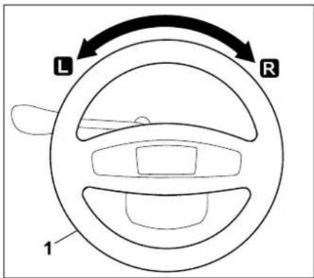
Turning the steering wheel (1) to the left L or right R changes the driving direction of the machine.
The further the steering wheel (1) is turned, the smaller the turning radius.
8.6 Driver's seat adjustment lever
The seat can be adjusted to seven notched positions.

- Stop the engine. (⇒ 11.3)
- Sit on the driver's seat.
- Put one hand on the steering wheel.
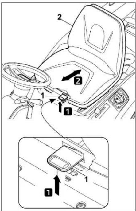
With the other hand, lift and hold driver's seat adjustment lever (1).
Move seat (2) to the desired position and then release driver's seat adjustment lever again.
Ensure that the driver's seat adjustment lever fully engages in the selected position when released.
8.7 Drive pedal
Note Befor
Before actuating the drive pedal, ensure that the correct driving direction is selected at the driving direction selector lever. If the parking brake is engaged or the brake pedal is pressed, the drive pedal cannot be actuated.
The driving speed can be continuously regulated via the drive pedal.

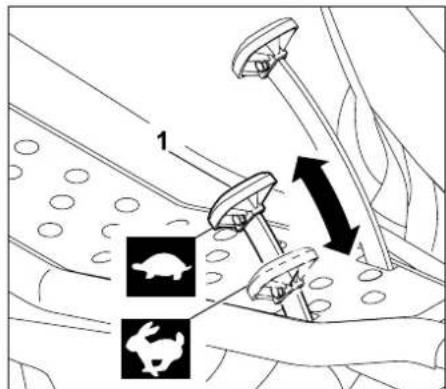
Stopping:
Take foot off the drive pedal (self-propulsion) (1).
Reducing the driving speed:
Reduce pressure on the drive pedal (1).

Increasing driving speed:
Press down drive pedal (1).

8.8 Brake pedal
The machine can be braked when driving and can be blocked at a standstill via the brake pedal.
Press brake pedal (1).
The more firmly brake pedal (1) is pressed, the more the rear wheels are braked.

Warning:
Never operate the machine with a defective brake.
Always have a defective brake repaired or adjusted by a specialist dealer.
VIKING recommends VIKING specialist dealers.
Never try to service the brakes yourself.
8.9 Parking brake
The rear wheels of the machine are blocked by the engaged parking brake. This prevents the ride-on mower from being set in motion inadvertently (e.g. on slopes etc.).

Note
Always check the function of the brakes before engaging the parking brake.
Engaging the parking brake
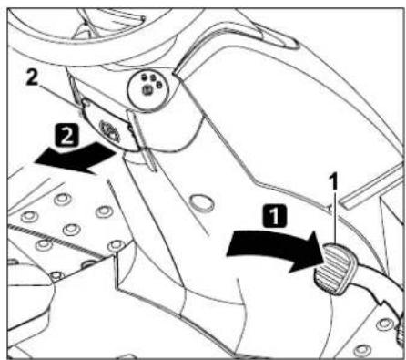
Press the brake pedal (1) down to the stop with the foot and hold.
Pull the parking brake (2) upwards.
- Release the brake pedal again. The parking brake is activated if the brake pedal remains in the pressed position.
- Release the parking brake lever. This swings downwards.
- The rear wheels are blocked.
Releasing the parking brake
Briefly press on brake pedal (1) with the foot.
- The brake pedal returns to the initial (unactuated) position.
- The parking brake is deactivated and the rear wheels are no longer blocked.
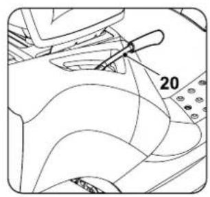
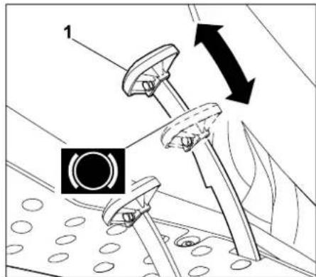
8.10 Cutting height adjustment lever
Six cutting levels can be set using the cutting height adjustment lever.
Unlocking the cutting height adjustment lever

Risk of injury:
Hold the lever firmly at the handle before releasing the cutting height adjustment lever.
For safety reasons, unlock the cutting height adjustment lever when the machine is at a standstill.
natural_image
Technical line drawing of a mechanical component with labeled parts (no text or symbols)
Pull the cutting height adjustment lever (1) inwards (towards the driver's seat) and hold.
- The cutting height adjustment lever is unlocked, and the cutting height can be adjusted.
Locking the cutting height adjustment lever
natural_image
Technical line drawing of a mechanical component with a lever and pin (no text or symbols)
Slowly guide the cutting height adjustment lever (1) outward with the hand until the cutting height adjustment lever engages in a notched position.
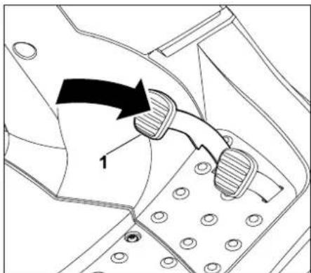
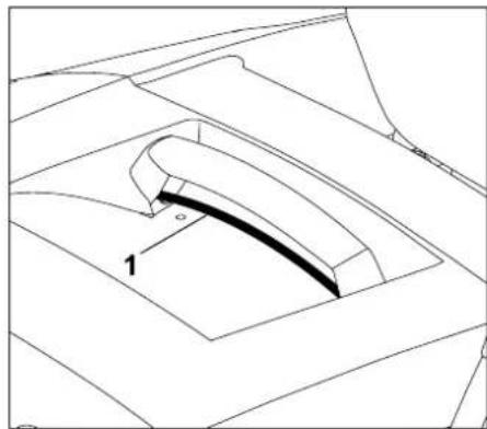
8.11 Grass catcher box emptying lever
The grass catcher box can be emptied comfortably using the grass catcher box emptying lever, without the user having to leave the driver's seat.

• Disengage the mowing deck. ( 8.3)
- Bring the machine to a standstill before emptying the grass catcher box.
- Press the brake pedal and hold or engage the parking brake.
natural_image
Line drawing of a truck's front wheel with a lever and upward arrow indicating motion (no text or symbols)
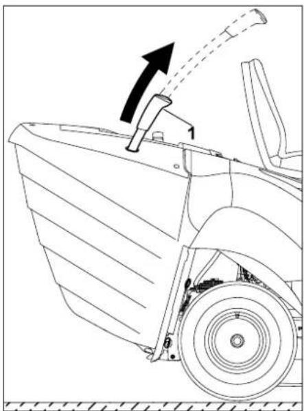
Pull the grass catcher box emptying lever (1) upwards.
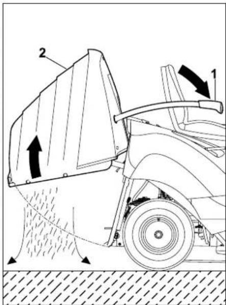
Press the grass catcher box emptying lever (1) forward (in direction of seat). The grass catcher box (2) swings upwards and the clippings fall out.
- Slowly move the grass catcher box emptying lever towards the rear and allow the grass catcher box to re-engage with the rear panel.
- Press the grass catcher box emptying lever downwards and move to the initial position.
8.12 Grass catcher box release lever

Warning:
Ensure that you do not pinch your fingers when actuating the grass catcher box release lever.
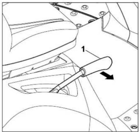
The grass catcher box release lever is located underneath the grass catcher box handle.
The grass catcher box release lever must be pulled upwards and held before attaching or detaching the grass catcher box.
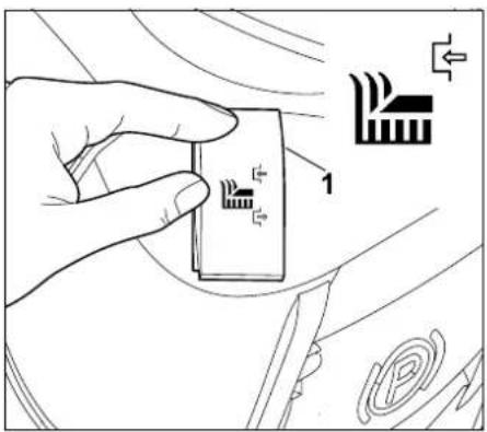
Releasing the grass catcher box:
natural_image
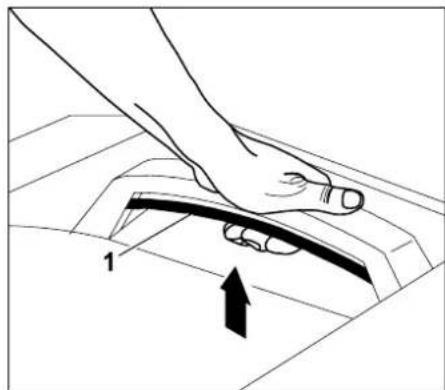
Line drawing of a hand pressing down on a mechanical component with an arrow indicating motion (no text or symbols)
Pull grass catcher box release lever (1) fully upwards and hold.
- The grass catcher box is released and can be removed.
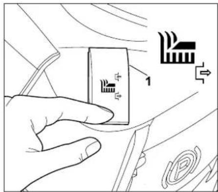
Locking the grass catcher box:
natural_image
Technical line drawing of a mechanical component with no visible text or symbols
After attaching the grass catcher box, release the pulled-out grass catcher box release lever (1). Ensure that the lock engages fully.
– Once locked, the grass catcher box is firmly attached to the machine again.
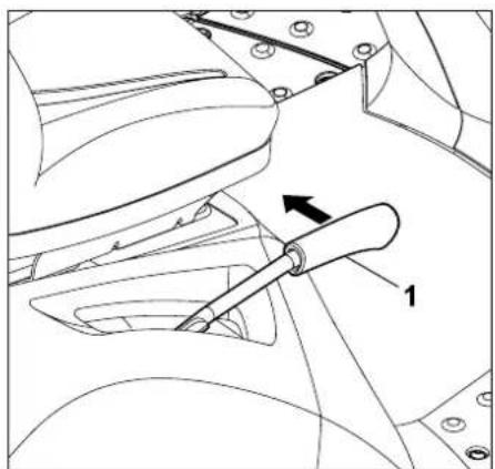
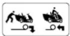
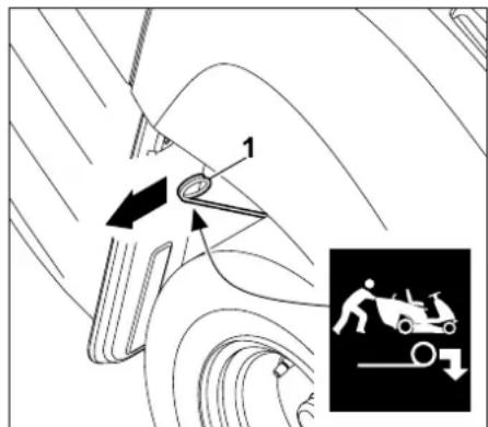
8.13 Gearbox freewheel lever
The gearbox can be disengaged (e.g. for pushing the machine) or engaged (for self-
propulsion) by means of the gearbox freewheel lever.

Warning!
Risk of crush injuries!
The gearbox freewheel lever should only be pulled out on level surfaces, as the machine may be set in motion.
If the machine is parked with the gearbox disengaged, the parking brake must always be engaged.

Note
The gearbox freewheel lever should only be pulled out when the ride-on mower is to be pushed.
Disengaging the gearbox
Pull the gearbox freewheel lever (1) outwards to the stop.
Engaging the gearbox
Lift up the gearbox freewheel lever (1) and then press it inwards to the stop.
8.14 Level sensor (grass catcher box)
The time for the filled grass catcher box signal is adjusted by modifying the length of the (grass catcher box) level sensor.
This allows you to adapt filling of the grass catcher box to the characteristics of the clippings.
A shorter sensor generally causes later triggering of the signal (the grass catcher box is filled to a greater extent, ideal for very dry clippings).
The level sensor can be adjusted to 6 notched positions.
In delivery condition, the level sensor (grass catcher box) is fully extended.
Adjusting the level sensor
- Stop the engine. (⇒ 11.3)
- Engage the parking brake. (⇒ 8.9)
- Remove the grass catcher box.
(⇒ 11.9)
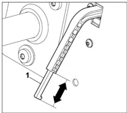
natural_image
Mechanical assembly diagram showing a lever mechanism with labeled component '1' and directional arrow (no text or symbols beyond basic labels)
Extend or shorten the level sensor by moving the slide (1) of the (grass catcher box) level sensor in the direction of the arrows.
- Attach the grass catcher box. (⇒ 11.9)
9. Notes on working with the machine

Warning: Risk of injury.
Before each use, observe all information regarding safe operation of the machine.
Working on slopes requires special concentration and care.

Note
Check the mowing deck for correct installation position before starting work.
Select a flat, even area for initial use of your machine and mow in straight and slightly overlapping strips for practising purposes.
Grass should always be mowed when dry.
A perfect, thick lawn is achieved by
- mowing at high engine speed (throttle lever in MAX position) and a slow driving speed;
– regular mowing and keeping the grass short;
– not cutting too short in hot, dry conditions as the lawn will be burnt by the sun and become unsightly;
- using a sharp mowing blade, therefore sharpen regularly;
– changing the cutting direction.
Mowing tall grass
If the grass is very high, it is better to mow it in two stages:
– use the highest cutting height, maximum engine speed and slow driving speed for the first mowing operation;
– for the second mowing operation, select the desired cutting height and set the maximum engine speed. Adjust the driving speed to the condition of the lawn.

Warning – fire hazard!
Avoid overloading the mowing deck drive. Overloading may lead to constant slipping of the V-belt and consequently to a fire hazard due to overheating.
Unusual running noise, e.g. a "squealing" (slipping noise) of the V-belt, indicates overloading. For this reason, never mow in high grass when the discharge chute is blocked or the grass catcher box is full; use a mulching kit (special accessory) if necessary.
The mowing deck, particularly the V-belt area, must always be kept free of combustible material (grass, leaves, etc.). It should also be cleaned regularly to prevent a fire hazard.
Preventing blockage of the discharge chute
If the discharge chute becomes blocked with grass, reduce the driving speed. This may be too high in relation to the lawn conditions. The slide of the level sensor should be fully pulled out. ( 8.14)
If the problem persists, the probable cause is damaged or worn highlift blade. Replace the mowing blade.
Furthermore, the mowing deck, discharge chute and mowing blade should be cleaned after each use to prevent the accumulation of grass deposits.
Fertilisation
Mowing the grass deprives the ground of permanent nutrients, which can be returned by using a high-grade, long-term lawn fertiliser. Usually, fertilising three times per mowing season is necessary. For this purpose, the lawn should be dry, so that the fertiliser does not stick to the grass blades and burns them. It is then better to water the lawn, which results in the fertiliser being flushed off the grass blades. (observe manufacturer's instructions for use.)
Natural fertilising is possible using lawn clippings. This is made possible by the use of the mulching kit. The mulching kit is available as a special accessory and is not included in the standard equipment. (Further information is available from your VIKING specialist dealer.)
Ground-conserving working
The most important factors for ground-conserving working are operating technique and ground moisture.
In order to achieve clean mowing results, the driving speed must be adapted to the condition of the grass to be mowed (height and density) and to the moisture of the lawn.
Executing curves that are too tight increases the loading on the turf and leads to poor mowing results, particularly on wet grass, as the wheels sink into the soft grass.
10. Safety devices
The machine is equipped with several safety devices for safe operation and for the prevention of improper use.

Risk of injury
If a safety device is found to be defective, the machine must not be operated. Consult a specialist dealer; VIKING recommends VIKING specialist dealers.
To start the engine, the following conditions must always be fulfilled:
- mowing blade switched off,
- brake pedal pressed or parking brake engaged.
The engine stops if the user:
— leaves the driver's seat with the mowing blade engaged,
- lifts the grass catcher box or removes the deflector (special accessory) with the mowing blade engaged,
– leaves the driver's seat without engaging the parking brake.
Integrated blade run-down brake:
Following disengagement, the mowing blades come to a standstill after 5 seconds at the latest.

Note
Following engagement of the mowing deck, the mowing blade turns and a wind noise is audible. The run-on time corresponds to the duration of the wind noise following disengagement. This can be measured using a stopwatch.
11. Operating the machine
- Carefully read and observe the section entitled "For your safety".
- Ensure that you are familiar with the controls of the machine.
– Before operating the machine, inspect the maintenance schedule and carry out all relevant maintenance instructions.
– Before each use, check that all safety devices are operating correctly.
No safety devices must be damaged, missing or modified.
Risk of injury:
For safety reasons, the machine must not be used on slopes with an inclination of more than 10^ (17.6%).
A slope inclination of 17.6% corresponds to a vertical height increase of 17.6 cm for a 100 cm horizontal distance.
11.1 Filling the fuel tank

Risk of injury:
Read and observe the section "For your safety" before opening the fuel tank cap. (⇔ 4.)

Do not fill the fuel tank completely, but fill to approx. 4 cm below the edge of the filler neck so that the fuel has room to expand.
Maximum tank capacity:
6 litres
Recommendation:
Fresh good quality fuel, normal unleaded petrol (see engine instruction manual).
- Stop the engine. (⇒ 11.3)
- Engage the parking brake. (⇒ 8.9)
Tank cap
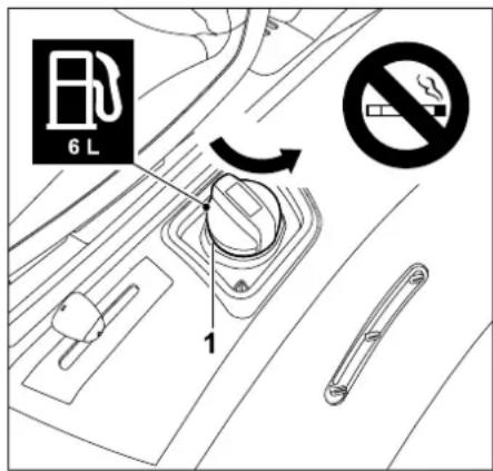
Unscrew and remove the tank cap (1).
- Fill the fuel tank using an appropriate funnel. Observe the tank display in order to prevent the fuel from overflowing.
Tank display

The fuel level can be read off via the tank display. When filling with fuel, the tank display is a visual aid to prevent overflowing.
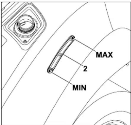
The fuel level in the tank can be read off via the tank display (2). Fill the tank with fuel until the fuel level has reached the upper marking.
- Screw on the tank cap. Then tighten the tank cap hand-tight.
- Wipe away any spilled fuel and allow it to evaporate before starting the engine.
11.2 Starting the engine

Risk of injury:
Before starting, carefully read and observe the section "For your safety". ( 4.)
Only start the machine when the user is sitting on the driver's seat.

When operating (e.g. mowing), the throttle lever should always be in the MAX position.

Avoid damage to the machine. If the engine fails to start, it must be noted that the engine can flood following several starting attempts. When attempting to start, the ignition key should never be held in the "start engine" position for more than a maximum of 10 seconds.
The following points must be noted before starting:
- Carefully read and observe the section entitled "For your safety". (⇒ 4.)
- Check the engine oil level. (⇒ 13.11)
- Remove grass residues from the mowing deck and engine compartment.
- Check the fuel.
- Before each use, check the braking function. ( 11.5)
- Perform all personal settings (driver's seat adjustment) on the machine. Not when the engine is running!
- Never start the machine in the vicinity of other persons, particularly children, or animals.
Starting sequence
The machine should be started in the following sequence:
- Open fuel cock. (⇒ 13.14)
- Before starting, press the brake pedal to the stop and hold or engage the parking brake. ( 8.8), ( 8.9)
- Check the mowing deck switch: The mowing deck must be disengaged. ( 8.3)
- Insert the ignition key in the ignition lock and turn to the "ignition on/engine running" position. ( 8.1)
- When the engine is cold:
Set throttle lever to the choke-position.
(⇒ 8.2)
When the engine is warm:
Set the throttle lever to the MAX-position. ( 8.2)
- Turn the ignition key to the "start engine" position.
The engine starts. As soon as the engine is running, release the ignition key. This returns automatically to the "ignition on/engine running" position.
- If the engine was started via the choke-position of the throttle lever, return the throttle lever to the MAX position when the engine is running. (note detent).
- The engine is running.
The foot can be removed from the brake pedal.
11.3 Stopping the engine

Disengage the mowing deck before stopping the engine.

Risk of injury:
For safety reasons, the ignition key must always be removed when leaving the machine after switching off the engine. Keep the ignition key where only authorised persons have access to it, in order to prevent use by children or other persons unfamiliar with the machine.
Furthermore, the parking brake must always be engaged before leaving the machine.
The engine should be switched off in the following sequence:
- Brake the machine to a complete standstill.
• Disengage the mowing deck. ( 8.3)
- Press the brake pedal to the stop and hold. ( 8.8)
- Set the throttle lever to the MIN position. ( 8.2)
- Turn the ignition key to the "engine off" position. The engine stops.
- Engage the parking brake if necessary. (⇔ 8.9)
- The foot can be removed from the brake pedal.
- Close the fuel cock if necessary.
(⇒ 13.14)
- If required, remove the ignition key and keep in a place where only authorised persons can access it.
11.4 Driving

Warning:
Before driving the machine, carefully read and observe the section "For your safety". (⇔ 4.) A low driving speed must always be selected on rough terrain. Before each change of direction, especially on slopes, the driving speed must be appropriately reduced.

Only regulate the driving speed via the drive pedal at maximum engine speed.
The following points must be noted before driving:
- Always check the braking function before driving.
- Engage the gearbox freewheel lever. ( 8.13)
- Bring the machine to a standstill and only then actuate the driving direction selector lever.
Forward driving:
- Start the engine. (⇒ 11.2)
- Set the throttle lever to the MAX-position. ( 8.2)
- Set driving direction selector lever to front position (forward driving direction). ( 8.4)
- Disengage the parking brake, if engaged. ( 8.9)
- By pressing the drive pedal, the driving speed is regulated and the machine moves forward.
Reversing:
- Start the engine. (⇒ 11.2)
- Set the throttle lever to the MAX-position. ( 8.2)
- Set driving direction selector lever to rear position (reverse driving direction). ( 8.4)
- Disengage the parking brake, if engaged. ( 8.9)
- By pressing the drive pedal, the driving speed is regulated and the machine moves backwards.
11.5 Braking

Risk of injury:
Before braking, reduce the driving speed by easing the pressure on the drive pedal:
If possible, refrain from braking abruptly at the maximum driving speed.

Before each use, check the braking function.
- Reduce driving speed.
- Press the brake pedal down evenly until the machine comes to a standstill.
11.6 Adjusting the cutting height

Risk of injury:
For safety reasons, the cutting height should only be adjusted when the machine is at a standstill.
- Brake the machine to a complete standstill.
- Unlock and hold the cutting height adjustment lever. ( 8.10)
- The cutting height can be adjusted by moving the cutting height adjustment lever upward or downward to 6 cutting levels.
- Lock the cutting height adjustment lever. ( 8.10)
Cutting level 1:
35 mm cutting height
Cutting level 6:
90 cm cutting height
11.7 Mowing
Before mowing, carefully read and observe the section "For your safety". ( 4.)
The maximum engine speed should always be set for mowing. The mowing blade is optimised for this speed and this produces the best cutting pattern as well as the most powerful suction effect for collection of the clippings.
If the mowing deck is engaged when driving, the engine speed is briefly reduced due to the additional load as the mowing blade starts to rotate. The engine then continues to run at the selected engine speed. Should the discharge chute become blocked or if the engine speed is reduced during a mowing operation, a lower driving speed or a higher cutting level should be selected.
In order to maintain a well-cut lawn, the section "Notes on mowing" should be read and observed before mowing. ( 9.)
The following points must be noted before engaging the mowing blade:
- No persons, particularly children or animals must be in the vicinity.
- The mowing deck can only be engaged if the grass catcher box or a deflector (special accessory) for rear discharge is correctly installed on the machine.
- Carefully inspect the complete area on which the machine is to be used and remove all stones, sticks, wire, bones and other foreign objects.
– Before engaging the mowing deck, visually inspect to determine whether the safety devices (V-belt covers, discharge chute etc.) are properly installed and are in good condition.
- Only engage the mowing blade at maximum engine speed.
- Only engage the mowing blade when the machine is already on the grass area to be mown.
- Do not engage the mowing blade in tall grass or when set to the lowest cutting level.
Engage the mowing blade in the following sequence:
- Start the engine. (⇒ 11.2)
- Set the throttle lever to the MAX-position. ( 8.2)
- Drive the machine onto the lawn.
- Do not engage the mowing deck in tall grass or when set to the lowest cutting level.
- Press the mowing deck button to engage the mowing deck. ( 8.3)
During mowing
- Always set the throttle lever to the MAX-position while mowing. ( 8.2)
- Always adapt the driving speed to the grass height/cutting level.
A low driving speed should be selected when mowing tall grass / at a low cutting level.
Disengage the mowing blade in the following sequence:
- Drive onto an area of grass which has already been mown or select the highest mowing deck cutting level. ( 8.10)
- Press the mowing deck button to disengage the mowing deck. ( 8.3)

Risk of injury:
After disengaging the mowing deck, beware of the mowing blade running on for several seconds before coming to a standstill (max. 5 seconds).
11.8 Emptying the grass catcher box

Risk of injury:
Only empty the grass catcher box on level surfaces, as the centre of gravity is changed by swinging up the grass catcher box and thus the danger of tipping over is increased.

A permanent continuous tone during mowing signals that the grass catcher box is completely full and must be emptied.
Disengage the mowing deck. The continuous tone ceases once the mowing deck has been disengaged.
Grass catcher box not being completely filled
- Check whether the discharge chute is installed. (⇔ 13.4)
-
Correctly adjust the level sensor (grass catcher box). (⇔ 8.14)
-
When emptying the grass catcher box, check the discharge chute for blockage and clean if necessary.
- Check the wings of the mowing blade for damage or wear and replace if necessary.
Emptying the grass catcher box
- Disengage the mowing deck. ( 8.3)
The continuous tone ceases.
- Select the highest mowing deck cutting level. ( 8.10)
- Drive the machine to the point at which the clippings are to be emptied.
- Pull out the grass catcher box emptying lever and push it forward. ( 8.11)
Grass catcher box swings upwards and the clippings fall out.
- With the grass catcher box raised, it may be necessary to drive forward slightly, so that the clippings can fall out of the grass catcher box.
- Briefly swing the grass catcher box up and down so that the all the clippings fall out.
- Slowly move the grass catcher box emptying lever towards the rear and allow the grass catcher box to re-engage with the rear panel.
- Release the grass catcher box emptying lever again and press down until it has returned to the initial retracted position.
11.9 Removing and attaching the grass catcher box
The following points must be noted before removing:
• Disengage the mowing deck. ( 8.3)
• Empty the grass catcher box. (⇒ 11.8)
- Engage the parking brake. (⇒ 8.9)
- Stop the engine. (⇔ 11.3)

When removing and attaching the grass catcher box, the grass catcher box release lever must always be held in the released position until the grass catcher box has been fully removed or attached.
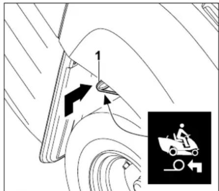
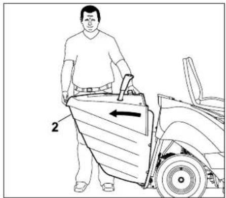
Removing the grass catcher box
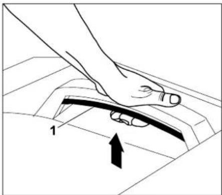
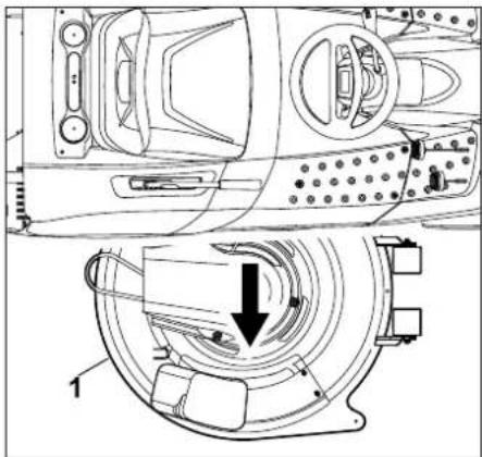
natural_image
Illustration of a hand pressing down on a mechanical component with an arrow indicating motion (no text or symbols)
Pull the grass catcher box release lever (1) upwards and hold.
natural_image
Line drawing of a person pushing a vehicle with a directional arrow (no text or symbols)
Remove the grass catcher box (2).
Attaching the grass catcher box
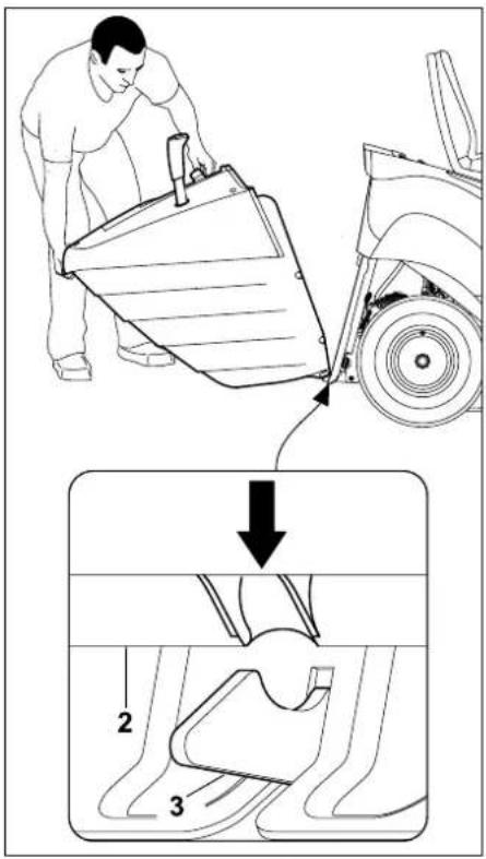
Position grass catcher box (2) on both snap-in hooks (3) on the rear panel.
- Actuate and hold the grass catcher box release lever. ( 8.12)
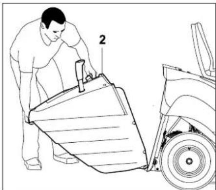
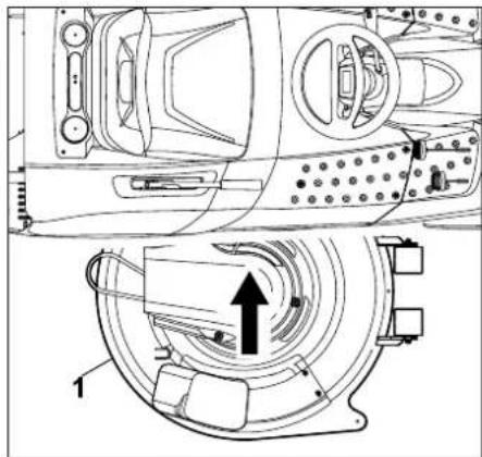
natural_image
Line drawing of a person pushing a large mechanical component next to a vehicle (no text or symbols)
Raise the grass catcher box (2) to the stop.
- Release the grass catcher box release lever and ensure that the grass catcher box engages. ( 8.12)
If the machine is operated without the grass catcher box or deflector (not included in standard equipment), the mowing deck cannot be engaged and the engine stops automatically.
11.10 Pulling loads

Risk of injury:
Before pulling or transporting loads using the machine, the section "For your safety" and especially the subsection "Pulling loads" must be carefully read and observed. Before attaching loads, always check the braking function. (⇒ 4.) The driving characteristics of the machine are changed when transporting loads (longer braking distances, select lower driving speed when changing direction etc.). The heavier the load, the more the driving characteristics are changed.

Avoid damage to the machine.
The maximum pulled load is decreased on inclines.
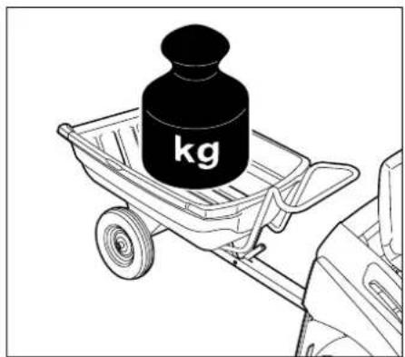
Maximum trailer weight on a level surface = 250 kg
Maximum trailer weight on a maximum 10^ inclination = 100 kg
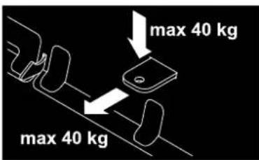
Maximum coupling load = 40 kg
Maximum pulled load = 40 kg

A pulled load of 40 kg at the trailer coupling is achieved when pulling a trailer with a weight of 250 kg on a level surface.
11.11 Operating on slopes

Warning:
Before operating the machine on slopes, the section "For your safety" and especially "Instructions for safe operation" must be carefully read and observed.(⇒ 4.) For safety reasons, the machine must not be used on slopes with an incline of more than 10° (17.6%). A slope inclination of 17.6% corresponds to a vertical height increase of 17.6 cm for a 100 cm horizontal distance. In order to ensure an adequate lubrication of the engine, the information in the accompanying engine instruction manual must be additionally observed when using the machine on slopes.
Check the braking function before operating the mower on slopes.
The following points must be noted:
- Slopes must be driven on in a longitudinal direction. Driving transversely increases the danger of tipping over.
- Changes of direction on slopes should be avoided.
- If changes of direction cannot be avoided, they must be executed with particular care.
11.12 Guide

Note
The accuracy of the guide depends on the body size of the user and on the adjustment of the driver's seat.
In order to prevent uncut grass being left between several mowing strips, the machine is equipped with a guide.
• The user sits on the driver seat.
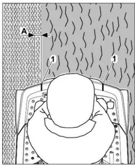
When the guide (1) is positioned precisely at the mowing edge (transition from already mown lawn to unmown lawn) as seen from the driver's seat, the lawn is cut with an overlap (A) of approx. 5 cm. This overlap ensures that the mowing blades cut approx. 5 cm into the already cut mowing strip. This ensures that no uncut grass is left between the two mowing strips.
- Mowing deck
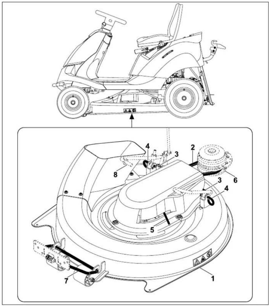
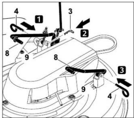
Overview of mowing deck components in installed condition
1 Mowing deck
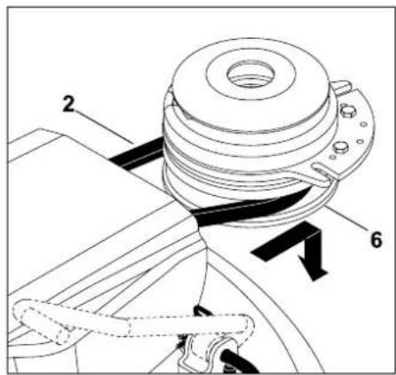
2 V-belt
3 Cotter pin
4 Retaining pin
5 V-belt tensioner lever
6 V-belt pulley
7 Front mowing deck mounting
8 Rear mowing deck mounting
12.1 Removing the mowing deck

Risk of injury:
Prior to all operations on the mowing deck, carefully read and observe the section "For your safety". (⇔ 4.)

Avoid damage to the machine.
When the mowing deck is removed, the machine must not be operated with the discharge chute installed. Remove the discharge chute so that it cannot catch on objects (molehills, roots, etc.) and become damaged. ( 13.3)
- Park the machine on level and solid ground.
- Stop the engine. (⇒ 11.3)
- Remove the ignition key.
- Engage the parking brake. (⇒ 8.9)
- Remove the grass catcher box.
(⇒ 11.9)
- Remove the discharge chute. (⇒ 13.3)
Removing rear V-belt cover

Danger of burns:
Allow the machine, particularly the exhaust system, to cool down completely before removing the rear V-belt cover.
- Select the lowest cutting level.
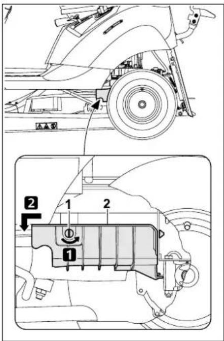
Step 1:
Remove closure screw (1) by turning through 90° anti-clockwise.
Step 2:
Pull the rear V-belt cover (2) forwards and remove.
Detaching the V-belt
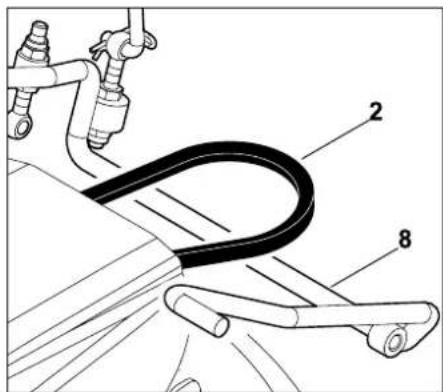
- Select cutting level 3.
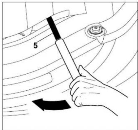
Press V-belt tensioner lever (5) in the direction of the arrow (forwards) using a suitable length of pipe and hold.
Remove V-belt (2) from V-belt pulley (6).
• After removing the V-belt, slowly release the V-belt tensioner lever.
Detaching the mowing deck at the rear

Danger of pinching:
Before pulling out the retaining pin, ensure that no body parts (hands, fingers, feet, etc.) are positioned directly under the mowing deck.

Note
To facilitate removal, note and carefully observe the specified sequence.
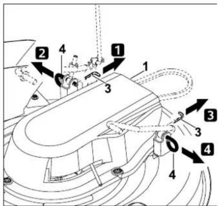
Step 1:
Remove the cotter pin (3) from the retaining pin (4).
Step 2:
Lift up the mowing deck (1) slightly and hold. Detach and remove the retaining pin (4).
Step 3:
Remove the cotter pin (3) from the retaining pin (4).
Step 4:
Lift up the mowing deck (1) slightly and hold. Detach and remove the retaining pin (4).
- Carefully and slowly set down the mowing deck.
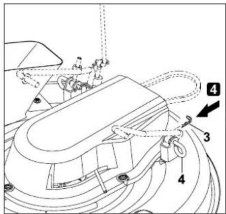
Detaching the mowing deck at the front

Danger of pinching:
Before detaching, ensure that no body parts (hands, fingers, feet, etc.) are positioned directly under the mowing deck.
After detaching the mowing deck, the front mowing deck mounting automatically swings upwards.
Push mowing deck (1) forwards and detach at the front mowing deck mounting (7).
Removing the mowing deck
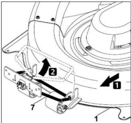
- Select cutting level 6.
natural_image
Technical line drawing of a mechanical device with internal components and a directional arrow (no text or symbols)
Pull out the mowing deck (1) on the right-hand side.
12.2 Installing the mowing deck

Risk of injury:
Prior to all operations on the mowing deck, carefully read and observe the section "For your safety". (⇔ 4.)
- Park the machine on level and solid ground.
- Stop the engine. (⇒ 11.3)
- Remove the ignition key.
- Engage the parking brake. (⇒ 8.9)
- Select the highest cutting level.
- Remove the grass catcher box. (⇒ 11.9)
- Remove the discharge chute. (⇒ 13.3)
Pushing in the mowing deck
- Select cutting level 6.
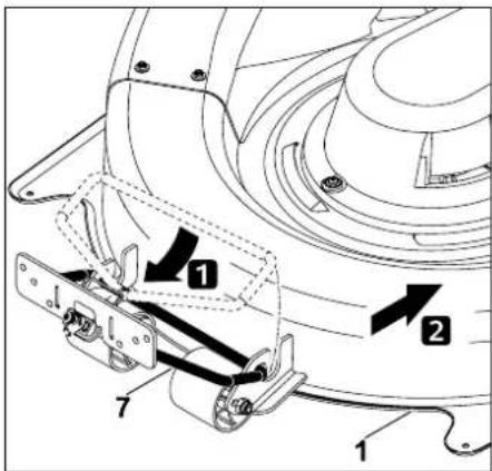
natural_image
Technical line drawing of a mechanical device with internal components and an arrow indicating motion (no text or symbols present)
Push the mowing deck (1) under the machine from the right-hand side with the rollers facing forward.
Position the V-belt (2) over the linkage of the mowing deck mounting (8).
Attaching the mowing deck at the front
- Select the lowest cutting level.
Swivel front mowing deck mounting (7) downwards and attach it to the mowing deck (1).
Push the mowing deck (1) slightly to the rear, attaching the front mowing deck mounting (7) to the mowing deck.
Attaching the mowing deck at the rear
Note
Before attaching, check that the mowing deck is correctly attached at the front mowing deck mounting.
- Raise mowing deck (1) with one hand and hold. The bores of the mounting on the mowing deck must be aligned with those of the mowing deck mounting on the machine.
Note
To facilitate installation, note and carefully observe the specified sequence.
Step 1:
Push the retaining pin (4) through the bores of the mounting on the mowing deck (9) and those of the mowing deck mounting (8) to the stop.
Step 2:
Insert cotter pin (3) through the bore in the retaining pin (4).
Step 3:
Push the retaining pin (4) through the bores of the mounting on the mowing deck (9) and those of the mowing deck mounting (8) to the stop.
Step 4:
Insert cotter pin (3) through the bore in the retaining pin (4).
Fitting the V-belt

Danger of pinching:
When fitting the V-belt, it must be ensured that the hands or fingers do not come between the V-belt and the V-belt pulleys when releasing the V-belt tensioner lever.
- Select cutting level 3.
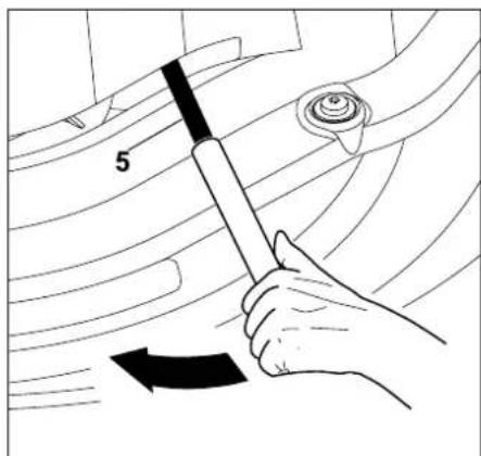
Press V-belt tensioner lever (5) in the direction of the arrow (forwards) using a suitable length of pipe and hold.
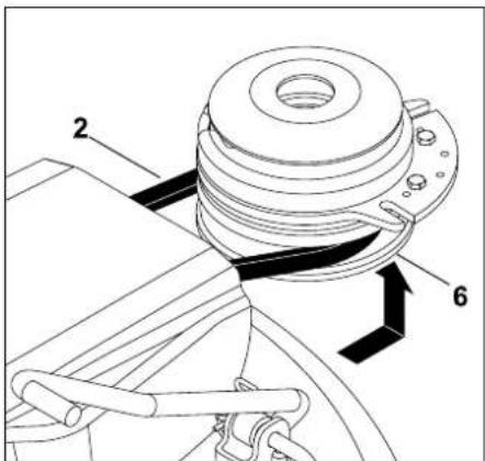
Fit V-belt (2) onto V-belt pulley (6). When fitting, ensure that the V-belt is installed correctly (not twisted).
- Slowly release V-belt tensioner lever (5) and ensure that the V-belt is routed correctly in the V-belt pulley.
• Install the discharge chute. (⇒ 13.4)
• Install the grass catcher box. (⇒ 11.9)

Risk of injury:
After attaching the mowing deck, perform an operational check. Ensure that no other persons, particularly children or animals are in the vicinity. Only perform the operational check when the user is sitting on the machine.
Installing rear V-belt cover

Danger of burns:
Allow the machine, particularly the exhaust system to cool down completely before installing the rear V-belt cover.
- Select the lowest cutting level.
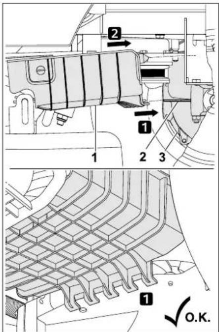
Insert the rear V-belt cover (1) with the retaining device at the locating lug (2) on the gearbox (3) in direction of arrow.
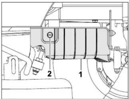
Push rear V-belt cover (1) upwards and hold. Turn the closure screw (2) clockwise through 90°.

Note
After installing, check that the rear V-belt cover is seated securely.

Avoid damage to the machine.
After installation, the V-belt must be free and must not contact the rear V-belt cover.
Check this visually.
13. Maintenance

Risk of injury:
Prior to all maintenance and cleaning work and before transport or immobilisation, it is essential to remove the ignition key and put it in a safe place, in order to prevent inadvertent starting of the engine.
Risk of injury:
Always wear gloves. Never touch the mowing blade before it has come to a standstill.
Always allow the engine and muffler to cool before carrying out maintenance and cleaning work.
Before all maintenance and repair work, carefully read and observe the section "For your safety" and especially the subsection
"Maintenance and repairs". ( 4.)
General

Risk of injury:
For safety reasons, maintenance operations on the brakes are not permitted.
Only allow adjustment and maintenance operations to be performed by a specialist dealer. VIKING recommends VIKING specialist dealers.
General maintenance instructions:
– The maintenance schedule and maintenance intervals must be strictly observed.
– In addition to the maintenance schedule provided in this instruction manual, the maintenance schedule and maintenance operations contained in the engine instruction manual must also be observed.
The following maintenance and repair work can be found in the engine instruction manual:
– Replacing the air filter.
- Information on engine oil (type, oil capacity, etc.).
- Checking and replacing the spark plug.
- Changing the fuel filter.
- Cleaning the engine.
It is essential that the following points are observed prior to all maintenance, repair and cleaning work:
– Park the machine on level and solid ground.
- Stop the engine. (⇒ 11.3)
- Remove the ignition key and keep it in a safe place.
- Engage the parking brake. ( 8.9)
- Allow the engine to cool down completely.
- Carefully read and observe the section "For your safety".
13.1 Maintenance schedule
All the instructions in the maintenance schedule must be strictly observed. Non-observance of the maintenance plan can lead to significant damage to the machine.

Note
Due to heavy-duty use, especially in professional operation, shorter maintenance intervals than those specified here may be required. Moreover, extreme external conditions such as sandy or stony ground, dust etc. may lead to shorter maintenance intervals than those specified in the instruction manual.
An inspection by a specialist dealer must be performed after every 100 operating hours or once a year. VIKING recommends VIKING specialist dealers.
Maintenance operations prior to initial use:
In order to achieve more efficient and safer operation and to prevent faults, it is important to be familiar with the condition of the machine.
For this purpose, the following checks are required before each start (visual inspection):
- Tyre pressure. ( 13.25)
– Wear and damage to tyres.
– Leaks in fuel carrying lines.
– Engine oil level (see engine instruction manual).
- Fuel-tank level.
– General visual inspection of the machine and mowing deck. Particularly the protective covers must be inspected for damage.
– Tightness of bolted connections.
Maintenance operations after each use:
- Cleaning the machine (mowing deck, discharge chute) and any attachments.
- Observe the instructions on cleaning the engine (see engine instruction manual).
– Clean the gearbox by brushing off grass residues and any other dirt.
Maintenance operations after the first 10 operating hours (initial operation):
- An inspection by your specialist dealer is recommended.
VIKING recommends
VIKING specialist dealers.
Maintenance operations after every 25 operating hours:
- Checking of blade fastening and blade sharpness, observe blade wear limit.
Maintenance operations after every 50 operating hours:
– General lubrication.
- Checking the installation position of the mowing deck. (⇒ 13.8)
Maintenance operations after every 100 operating hours:
– Replacing the mowing blade.
- Allow inspection to be carried out by a specialist dealer.
VIKING recommends
VIKING specialist dealers.

Note
During the inspection by the specialist dealer, the braking function is checked and, if necessary, the brakes are serviced. Furthermore, all required maintenance operations on the gearbox are carried out.
13.2 Lubrication
Lubricate the two front steering knuckles via the two grease nipples on the front axle.

Note
Before lubricating, the front axle must be unloaded by supporting appropriately.
The grease nipple must be cleaned before lubricating, so that no dirt enters the steering knuckle.
Escaping grease should always be removed (wiped off) after lubricating.
Use commercially available lubricating grease.
Lubricating
- Stop the engine. (⇔ 11.3)
- Remove the ignition key and keep it in a safe place.
- Engage the parking brake. (⇒ 8.9)
- Unload the front axle by supporting (lifting) it.
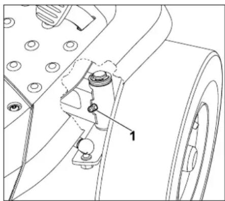
natural_image
Technical line drawing of a mechanical component with labeled parts (no text or symbols present)
Using a grease gun (not included in standard equipment), inject grease on both sides via the grease nipples (1) until small amounts of grease escape from the steering knuckles.
- Remove escaped lubricating grease.
- Remove support for front axle.
13.3 Removing the discharge chute
For better cleaning of the discharge chute, it is possible to remove the discharge chute without the use of additional tools.
The following points must be observed before removal:
- Stop the engine. (⇒ 11.3)
- Remove the ignition key and keep it in a safe place.
- Engage the parking brake. (⇒ 8.9)
- Remove the grass catcher box. (⇔ 11.9)
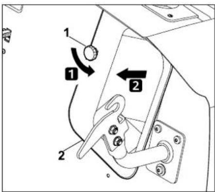
Unscrew and remove the retaining nut (1). Remove the discharge chute (2).
Avoid damage to the machine.
Reinstall the discharge chute immediately after cleaning so that this is not forgotten.
13.4 Installing the discharge chute
Avoid damage to the machine.
When pushing in, ensure that the discharge chute fits over the discharge opening of the mowing deck on all sides.
Note
When cleaning the discharge chute or each time it is removed, also check the level sensor (grass catcher box) and clean if necessary.
The following points must be observed before installation:
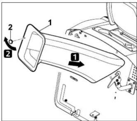
Push the discharge chute (1) in to the stop and position it over the discharge opening in the mowing deck.
Screw in the retaining nut (2) and tighten.
13.5 Cleaning the level sensor (grass catcher box)
Note
The level sensor (grass catcher box) may become soiled when mowing wet or moist grass.
This results in impaired function. If the level sensor (grass catcher box) cannot be easily moved as described below, it must be cleaned carefully using a brush.
By way of prevention, the level sensor (grass catcher box) should be cleaned following each mowing operation or each time the discharge chute is cleaned.
- Stop the engine. (⇒ 11.3)
- Remove the ignition key and keep it in a safe place.
- Engage the parking brake. (⇒ 8.9)
- Remove the grass catcher box. (⇔ 11.9)
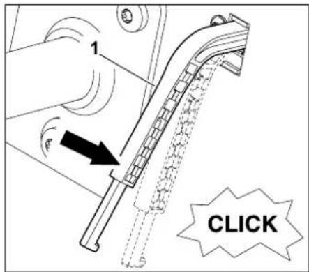
Using slight pressure, press level sensor (grass catcher box) (1) downwards. For this purpose, the level sensor (grass catcher box) (1) must be easy to move and a quiet "clicking" of the switch must be audible.
After releasing the level sensor (grass catcher box) (1), it must automatically return upwards to the initial position.
If the level sensor (grass catcher box) is soiled, it must be cleaned carefully using a brush (not included in standard equipment) and without water.
13.6 Checking the safety devices

Risk of injury!
The safety devices must only be checked from the driver's seat. No persons, particularly children or animals must be in the vicinity. Proper functioning of the safety devices must be checked at least once a month.
Following longer periods without use, for low-use machines or after repairs, always check all safety devices before using again.
Check the brake switch:
- The user must be seated on the driver's seat.
– The grass catcher box must be installed.
- Stop the engine and allow it to come to a standstill.
- Disengage the mowing deck. (⇒ 8.3)
- Do not actuate (press) the brake pedal or release the parking brake.
- If the brake switch is functioning, it should not be possible to start the engine.
Check the mowing deck switch:
- The user must be seated on the driver's seat.
- Press the brake pedal to the stop and hold. ( 8.8)
- Engage the mowing deck. (⇒ 8.3)
- It should not be possible to start the engine if the mowing deck switch is functioning.
Check the seat switch:
- The user must be seated on the driver's seat.
- Start the engine and allow it to run at maximum engine speed. ( 11.2), ( 8.2)
- Engage the mowing deck. ( 8.3)
- Relieve the weight on the driver's seat by standing up slowly and carefully. Do not dismount!
- If the seat switch is functioning, it should not be possible to start the engine.
- The user must be seated on the driver's seat.
- Start the engine and allow it to run at maximum engine speed. ( 11.2), ( 8.2)
- Engage the mowing deck. ( 8.3)
- From the driver's seat, tilt (empty) the grass catcher box upwards using the grass catcher box emptying lever. ( 11.8)
- The engine should stop and the mowing deck should disengage if the grass catcher box switch is functioning.
Check the grass catcher box switch:
13.7 Mowing blade maintenance

Risk of injury:
Always wear gloves. If you do not have the necessary expertise or auxiliary equipment, please always contact a specialist dealer. (VIKING recommends VIKING specialist dealers).
VIKING recommends the use of original VIKING spare parts.
Never touch the mowing blade before it has come to a standstill.
Always set down the mowing deck on a non-slip surface.
Maintenance interval:
Every 25 operating hours
Maintenance operations:
– Check the mowing blade wear limits:
- Sharpen the mowing blade if necessary.
If mowing results deteriorate, the mowing blade should be sharpened.
Checking the mowing blade wear limits

Risk of injury:
A worn mowing blade may break off and cause serious injuries. The instructions for blade maintenance must therefore always be observed. Mowing blades are subjected to differing degrees of wear depending on the location and duration of use. If you use the machine on sandy ground or use it frequently under dry conditions, the mowing blade will be subjected to greater loads and will wear more quickly than normal.
Caution:
Always replace the blade fastening screw and the retaining washer when replacing the mowing blade.

VIKING recommends removing the mowing deck if the wear limits need to be checked.
If a suitable lifting platform is available, the mowing blade wear limits can also be checked with the mowing deck installed.
- Carefully clean the mowing blade and mowing deck.
- Remove the mowing deck. (⇒ 12.1)
Placing the mowing deck in safe position for checks
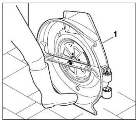
Lean mowing deck (1) against a wall and secure against slipping with the foot.
Checking the wear limits
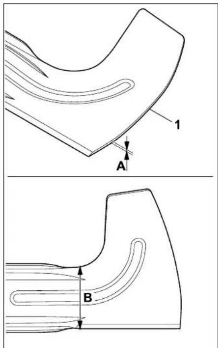
A = blade thickness
B = blade width
Blade thickness A:
The mowing blade (1) must be at least 2.5 mm thick at all points.
Check the thickness of the blade at several points using a slide calliper (1).
If the blade thickness is less than 2.5 mm at any point, the mowing blade must be replaced.
Blade width B:
Measure the distance (B) using a slide calliper.
For safety reasons, distance (B) must be at least 65 mm.

Risk of injury:
If the specified wear limits are reached or exceeded, the mowing blade must be replaced.
Removing mowing blade
- Remove the mowing deck. (⇒ 12.1)
- Lean the mowing deck against a wall and secure against slipping.
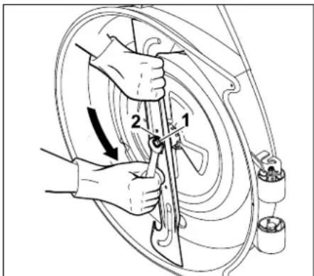
Loosen and remove the blade fastening screw (1) using an A/F 17 spanner (not included in standard equipment).
Remove the blade fastening screw (1) together with retaining washer (2). Remove the mowing blade (3).
Sharpening the mowing blade

Risk of injury:
Always wear safety glasses and gloves when sharpening.
The following points must be observed when re-sharpening mowing blades:
- Cool the mowing blade when sharpening, e.g. with water. The blade must not be allowed to display blue colouring, as this would reduce its cutting quality.
- Sharpen blades evenly to prevent vibration due to imbalance.
- The cutting angle of 30^ must be observed.
- Observe the wear limits when sharpening.

Risk of injury:
When resharpening the mowing blade, it is essential that the wear limits and the cutting angle of 30^ are observed.
The mowing blade must be replaced if notches or cracks are detected, or if the specifications contained in the section "Checking the wear limits" are exceeded.
Checking the balance of the mowing blade
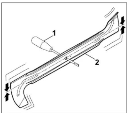
Insert a screwdriver 1 through the central bore.
When mowing blade (2) is properly balanced, it must balance in the position illustrated.

Risk of injury:
If the mowing blade does not balance, the procedure "Sharpening the mowing blade" must be repeated until the blade is balanced.
The mowing blade may only be balanced by means of sharpening back or cutting.
Installing the mowing blade:

Risk of injury:
Before installing, check the mowing blade for damage (notches or cracks) and wear.
Worn or damaged mowing blades must be replaced.
Replace the retaining washer each time the blade is installed.
Additionally secure the blade fastening screw (18) with Loctite 243.
Observe the specified torque of 65 - 70 Nm when tightening the blade fastening screws, as the secure attachment of the cutting tool depends on this.
The following points must be observed when attaching the mowing blade:
- Install the mowing blade with the curved edges/vanes pointing upwards (towards the mowing deck).
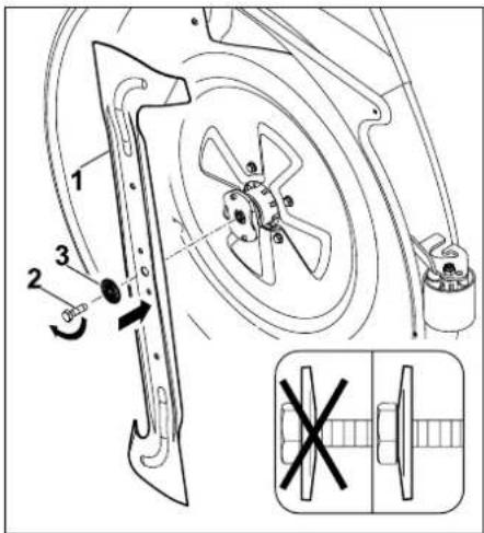
Attach the mowing blade (1), screw in blade fastening screw (2) with retaining washer (3) (observe convexity of retaining washer) and tighten to a torque of 65 - 70 Nm.
13.8 Checking the installation position of the mowing deck
Maintenance interval:
Every 50 operating hours.
The mowing deck should be checked every 50 operating hours or as required (e.g. following severe impacts to the mowing deck).

Risk of injury:
For all operations on the mowing deck, stop the engine and remove the ignition key.
Never reach under the mowing deck when the blade is rotating.
Before checking the correct installation position of the mowing deck, the tyre pressures of all the tyres must be checked and, if necessary, adjusted. (⇒ 13.25) Differences in the tyre pressures influence the positioning of the mowing deck.
If the installed mowing deck is not correctly positioned with respect to the ground, the cutting pattern can be negatively influenced.
The mowing deck is in the correct installation position when front of the mowing deck is slightly lower than the rear. The mowing deck is tilted slightly forwards.
- Park the machine on level ground.
- Stop the engine. (⇒ 11.3)
- Engage the parking brake. (⇒ 8.9)
- Remove the ignition key and keep it in a safe place.
- Select the lowest cutting level. (⇒ 8.10)
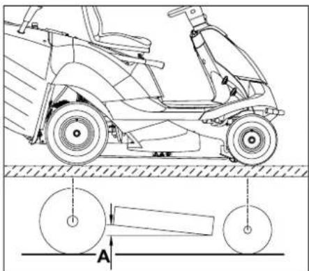
Distance A = 10 mm.
13.9 Changing the wheels
In the case of damage (holes, cracks, cuts, etc.) to the wheels, remove the damaged wheel and take it to a specialised dealer.
Lifting and supporting the machine

Risk of injury:
When lifting the machine, it must be noted that it is very heavy (see section "Technical specifications"). ( 20.) If necessary, raise the machine with the help of a second person or using a jack (not included in the standard equipment).

Avoid damage to the machine
When supporting, ensure that only the axle or the rear panel of the machine contacts the support. Only lift the machine at suitable components (e.g. frame, bumper, rims, axle). Never lift or support the machine at plastic parts.
• Park the machine firm and level ground.
- Stop the engine. (⇒ 11.3)
- Engage the parking brake. (→ 8.9)
- Remove the ignition key and keep it in a safe place.
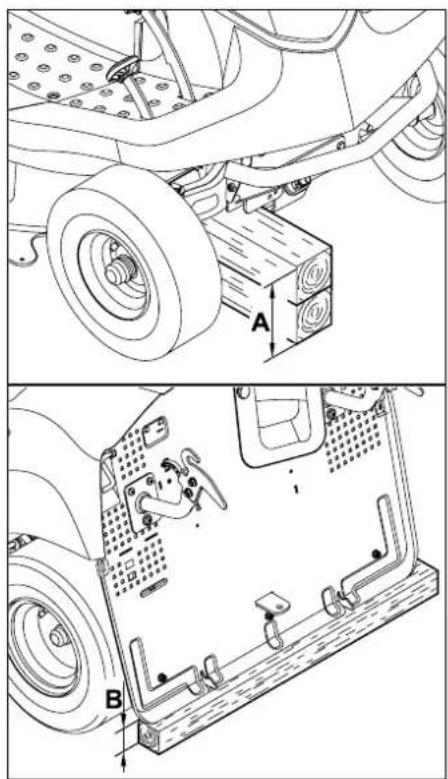
Front axle: A = minimum 200 mm
Rear axle: B = minimum 120 mm
Removing wheel
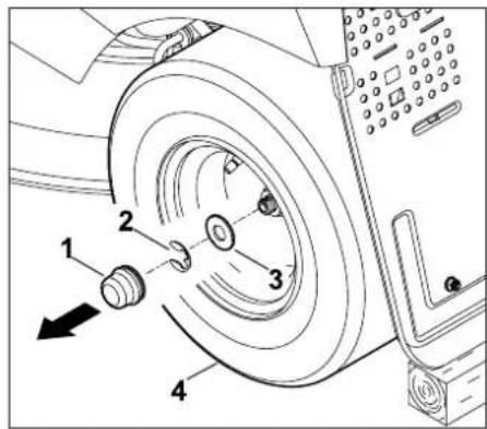
Remove the cap (1). Remove the retaining ring (2) using a screwdriver.
Pull the large washer (3) together with the wheel (5) off the wheel axle.
When removing the rear wheels, ensure that the couplers (feather keys) are not lost.
Installing wheel
Before installing the rear wheels, ensure that a coupler (feather key) is located in the groove of the wheel axle on both sides.
The following points must be observed before installing the wheels:
- Remove dirt from the wheel axle.
- Lightly coat the wheel axle with grease before installation.
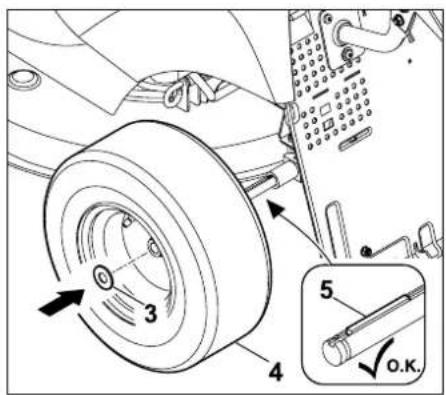
Insert feather key (5) in the rear wheel axle. Push the wheel (4) with the large washer (3) onto the wheel axle.
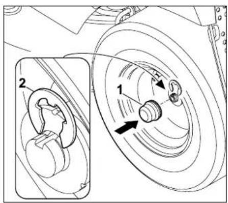
Allow retaining ring (2) to engage into the groove on the wheel axle.
Fit cap (1) onto the wheel axle.
13.10 Engine cover
The engine cover can be folded up in order to perform maintenance and cleaning work on the engine. Sufficient space is available for these operations when the engine cover is folded up.

Risk of injury:
Engage the parking brake, remove the ignition key and keep it in a safe place before folding up the engine cover.
The following points should be observed when folding up the engine cover.
- Park the machine on level and solid ground.
- Stop the engine. (⇒ 11.3)
- Remove the ignition key and keep it in a safe place.
- Engage the parking brake. (⇒ 8.9)
- Remove the grass catcher box. (⇒ 11.9)
- Remove the discharge chute. (⇒ 13.3)
- Allow the engine to fully cool down.
- Remove the mowing deck. (⇒ 12.1)
Detaching the engine cover:

Danger of pinching:
Before detaching the cutting height adjustment rod, ensure that no body parts (hands, fingers, feet, etc.) are positioned directly under the mowing deck.
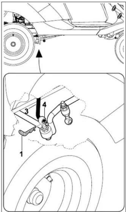
Remove the retaining pin (1) on the right-hand side of the rear mowing deck mounting (4).
Detach the cutting height adjustment rod (3) from the rear mowing deck mounting (4).
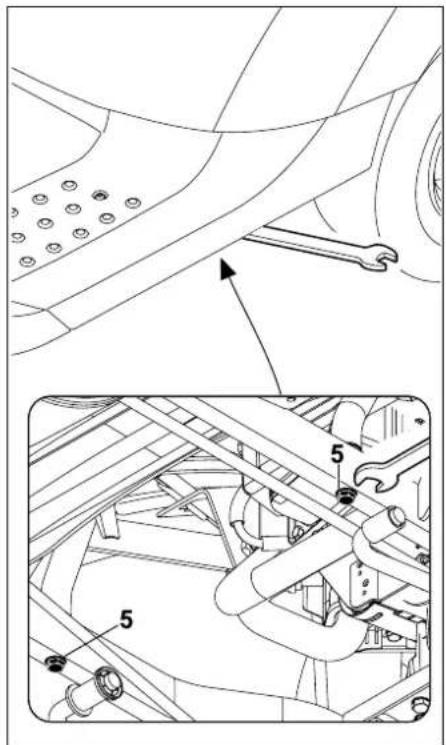
Unscrew and remove screws (5).

Safeguard against loss.
The screws cannot be removed when unscrewed.
Folding up the engine cover:

Risk of injury:
Always fold the engine cover up fully to the stop so that the catch engages in the frame. This prevents the engine cover from falling shut unintentionally.
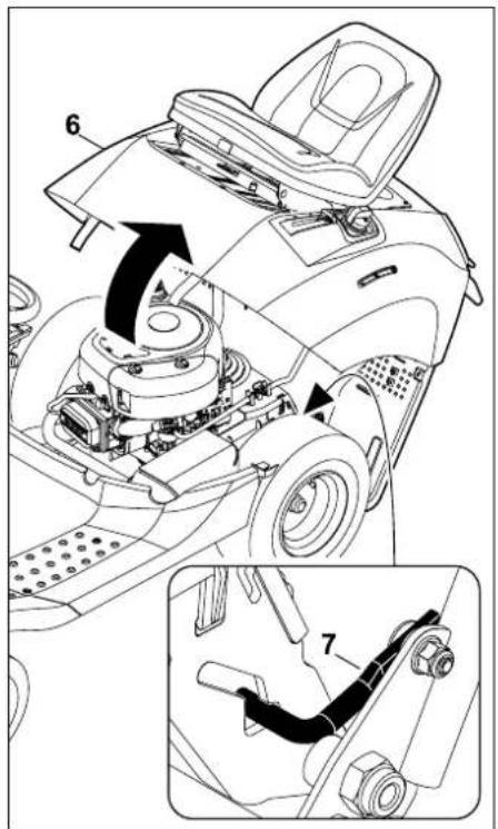
Fold engine cover (6) up to the stop. Ensure that the catch (7) engages correctly in the frame.
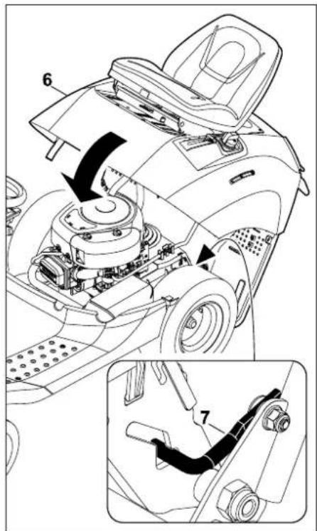
Push the engine cover (6) forward slightly and hold.
Release (lift) the catch (7) and slowly lower the engine cover (6).
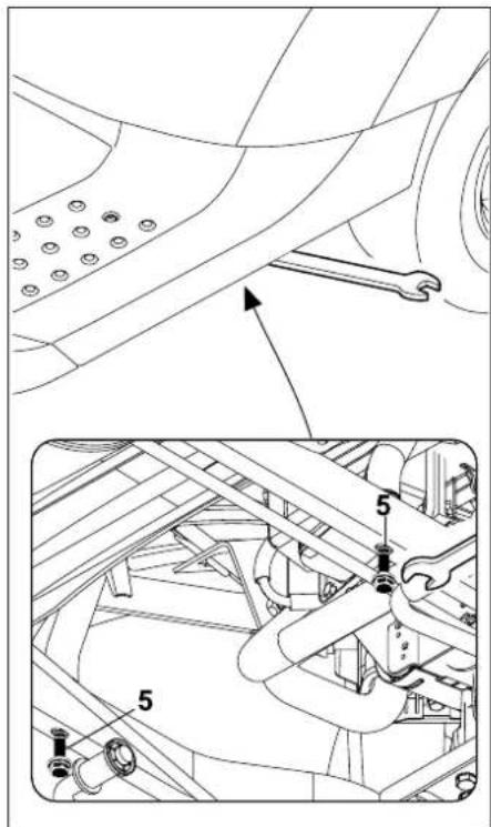
Screw in both screws (5) and tighten to 21 - 25 Nm.
Closing the engine cover

Danger of pinching:
Ensure that no body parts can be pinched before closing.
Close the engine cover slowly and carefully.
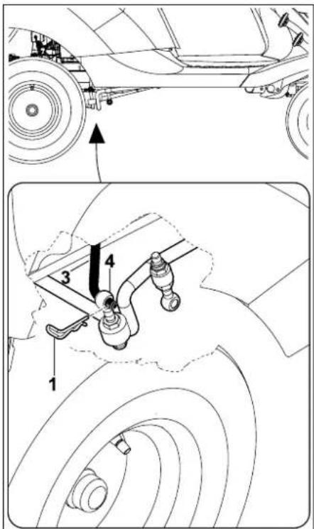
Insert the cutting height adjustment rod (3) into the bore in the mowing deck mounting (4).
Insert the retaining pin (1).
• Install the mowing deck. (⇒ 12.2)
• Install the discharge chute. (⇒ 13.4)
- Attach the grass catcher box. (⇒ 11.9)
13.11 Checking the engine oil filling level

Avoid damage to the machine.
Check the engine oil filling level before initial use and before each use.
- Park the machine on a flat, level surface.
- Stop the engine. (⇒ 11.3)
- Engage the parking brake. (⇒ 8.9)
- Allow the engine to cool down.
- Open the storage compartment.
(⇒ 13.26)
Please consult the engine instruction manual for instructions on checking the engine oil filling level.

Note:
If there is insufficient or no engine oil, the engine oil must be topped up.
- Close the storage compartment. ( 13.26)
13.12 Changing the engine oil

Danger of burns!
Allow the engine to fully cool down before topping up the engine oil and before changing the engine oil. Spilled engine oil may be ignited! Exercise particular caution when draining the engine oil. The engine oil may be hot.

Information regarding engine oil and oil capacity can be found in the engine instruction manual.
Perform an oil change when the engine is warm to the touch. Place a suitable oil collection container (note engine oil capacity) under the oil drain tube.
Dispose of used oil in conformance with statutory requirements.
Oil change interval:
The recommended oil change intervals can be found in the engine instruction manual.
Draining the engine oil:
- Stop the engine. (⇒ 11.3)
- Engage the parking brake. (⇒ 8.9)
- Remove the ignition key and keep it in a safe place.
- Remove the discharge chute. (⇒ 13.3)
- Allow engine to cool down (warm to the touch).
- Open the storage compartment.
(⇒ 13.26)
- Unscrew the oil cap (see also engine instruction manual).
MR 4082:
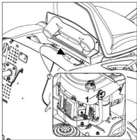
The oil drain hose (1) is located on the engine, near the right-hand rear wheel.
- Place a suitable oil collecting container underneath.
- Detach the oil drain hose.
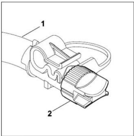
Turn the quick release cap (2) of the oil drain hose (1) half a turn anti-clockwise and remove.
Drain all the engine oil.
- Close the quick-release cap.
- Attach the oil drain hose to the engine.
MR 4082 K:
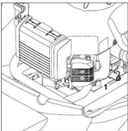
natural_image
Technical line drawing of a mechanical assembly with no visible text or symbols
The oil drain tube (1) is located on the engine, near the left-hand rear wheel.
- Place a suitable oil collecting container underneath.
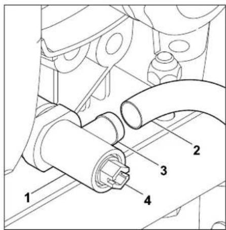
Fit a suitable hose (2) onto the branch tube (3) of the oil drain tube (1).
Open the oil drain plug (4) using a spanner (10 A/F) or a screwdriver (anti-clockwise) and completely drain the engine oil.
- Close the oil drain plug.
- Remove the hose.
13.13 Topping up engine oil

Avoid damage to the machine
Avoid exceeding and falling below the correct engine oil level.

Note
Before topping up the engine oil, check the engine oil level. Please consult the engine instruction manual for the type of engine oil to be used and the oil capacity.
VIKING recommends using a funnel when filling the tank with fuel (not included in standard equipment).
Use a suitable funnel and hose (neither included in standard equipment) when topping up the engine oil.
Insert the funnel into the hose so that the engine oil can be filled into the funnel and then flows through the hose.
- Open the storage compartment.
(⇒ 13.26)
Please consult the engine instruction manual for instructions on topping up the engine oil.
Use a funnel and hose to fill in the engine oil.
- Close the storage compartment.
(⇒ 13.26)
13.14 Fuel cock
The flow of fuel in the fuel line is enabled or interrupted by opening or closing the fuel cock.
The fuel cock is located behind the left-hand rear wheel.
- Stop the engine.
- Engage the parking brake.
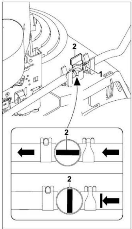
The fuel cock (1) is opened and closed via the control valve (2).
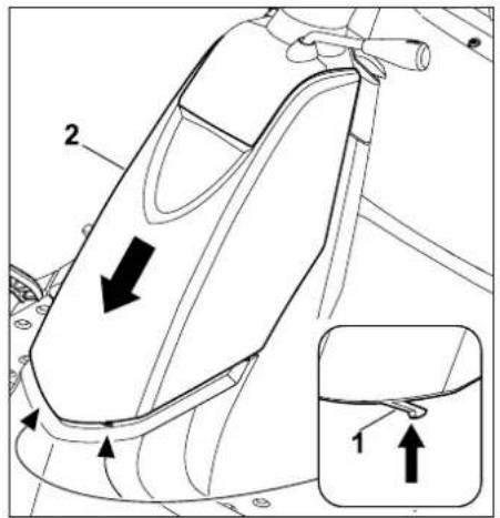
Press the two retaining lugs (1) inwards slightly and hold. Pull the steering column cover (2) downwards and remove.
13.16 Installing steering column cover
- Stop the engine. (⇒ 11.3)
- Engage the parking brake. (⇒ 8.9)
- Remove the ignition key and keep it in a safe place.
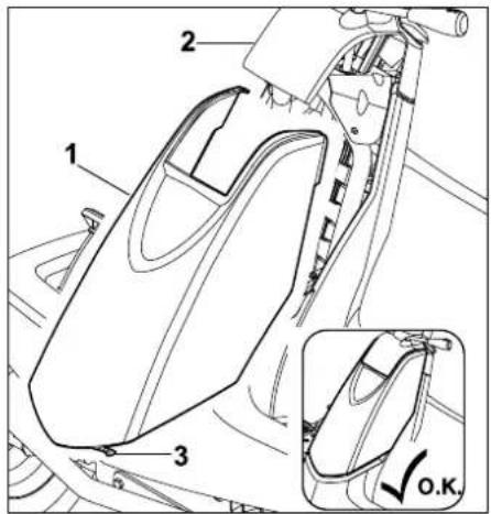
Insert the steering column cover (1) upwards into the dashboard (2) from below.
Guide the retaining lugs (3) into the openings (4). Allow the steering column cover (1) to engage by pressing slightly.
13.17 Fuses

Fire hazard:
Never bypass the fuses with wire or foil.
Never use a fuse with a value that differs from the specified rating (ampere).

If a new fuse blows within a short time, an electrical fault (e.g. short circuit) is the probable cause.
We recommend that you consult a specialist dealer. VIKING recommends VIKING specialist dealers.
- Stop the engine. (⇒ 11.3)
- Engage the parking brake. (⇒ 8.9)
13.15 Removing steering column cover
Checking the fuses
Plug-in fuses:
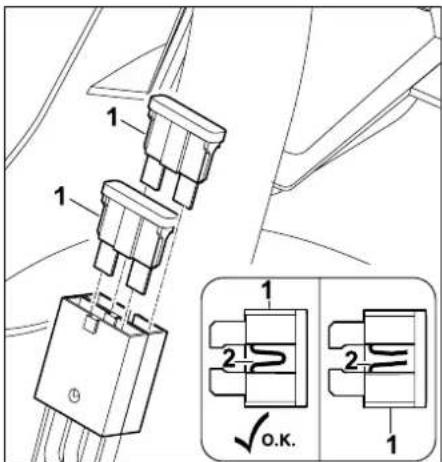
Remove the plug-in fuses (1). By visual inspection, check whether the wire (2) in the plastic is damaged (burnt through). Replace the fuse if the wire (2) is damaged.
Main fuse:
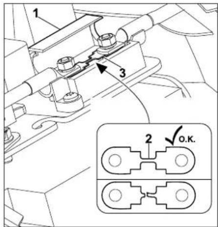
Open the cover (1).
By visual inspection, check whether wire (2) is damaged (blown). If the wire is damaged, fuse (3) must be replaced by a specialist dealer.
VIKING recommends VIKING specialist dealers.
- Close the cover.
- Install the steering column cover. (⇒ 13.16)
Replacing the fuses
- Remove the steering column cover.
(⇒ 13.15)
Plug-in fuses:
- Check the plug-in fuses.
10 Ampere fuse (red)
15 Ampere fuse (blue)
Model Charging device Electrics
MR 4082 10 A 10 A
MR 4082 K 15 A 10 A
Main fuse:
150 Ampere
For safety reasons, the main fuse must only be replaced by a specialist dealer. VIKING recommends VIKING specialist dealers.
• Install the steering column cover.
(⇒ 13.16)
13.18 Battery

Risk of injury:
When disconnecting the battery, always remove the black negative (−) cable first and only then, the red positive (+) cable.
When connecting the battery, always connect the red positive (+) cable first.

The battery is maintenance free and must only be replaced if it is damaged and must be removed in the case of prolonged immobilisation (e.g. winter break). Remove battery before disposing of the machine.
Do not dispose of the battery with domestic waste, but hand it in to a specialist dealer or at a hazardous waste collection point.
- Stop the engine.(⇒ 11.3)
- Engage the parking brake. (⇒ 8.9)
- Remove the ignition key and keep it in a safe place.
- Remove the steering column cover. (⇔ 13.15)
Disconnecting the battery:
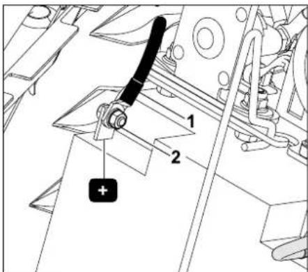
Unscrew the nut (1) from black connection cable (2) using two A/F 8 spanners and remove the screw, washer and nut. Detach and remove the connection cable (2) from the battery negative (-) terminal.
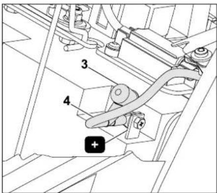
Remove the cap (3). Unscrew the connection of the red connection cable (4) from the battery positive (+) terminal using two A/F 8 spanners and remove the screw, washer and nut.
Detach and remove the connection cable (4) from the battery positive (+) terminal.
- Remove the battery if necessary.
(⇒ 13.18)
- Reattach screws, washers and nuts to the battery negative (−) and positive (+) terminals for safe keeping.
• Install the steering column cover if necessary. ( 13.16)
Connecting the battery:
The charge condition should be checked before installation. If the battery voltage is lower than 11.5 V, recharge the battery using a battery charger before installation.
- Insert the battery. (⇒ 13.18)
- If necessary, remove the screw, washer and nut from the battery.
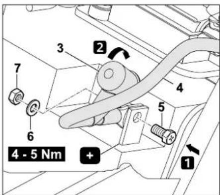
Step 1:
Attach the terminal connector of the red connection cable (4) (+) to the battery positive (+) terminal.
Insert screw (5) through the bore in the positive terminal and through the bore in the connection cable. Fit washer (6) onto the screw (5) and screw on the nut (7). Tighten the connection to a torque of
4-5 N m using two A/F 8 spanners.
Step 2:
Fit cap (3) onto the connection.
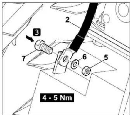
Step 3:
Attach the terminal connector of the black connection cable (2) (−) to the battery negative (−) terminal.
Fit washer (6) onto the screw (5). Insert the screw (5) through the bore on the battery and attach the terminal connector.
Screw on the nut (7) and tighten to a torque of 4 - 5 Nm using two A/F 8 spanners.
Removing the battery:
- Remove the steering column cover. (⇔ 13.15)
- Disconnect the battery. (⇒ 13.18)
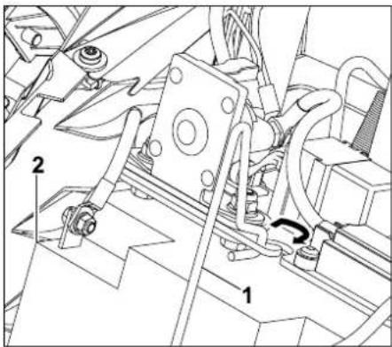
Open the retaining clasp (1) Remove the battery (2).
- Close the retaining clasp.
• Install the steering column cover.
(⇒ 13.16)
Inserting the battery
- Remove the steering column cover. (⇒ 13.15)
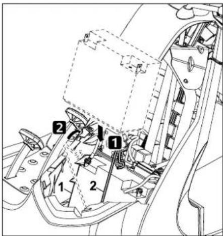
Insert the battery (1). Close the retaining clasp (2).
- Connect the battery. (⇔ 13.18)
• Install the steering column cover.
(⇒ 13.16)
Charging the battery:

Risk of injury:
In order to charge the battery using another charging system, the battery must be removed.
Furthermore, the specifications on the battery supplementary sheet and on the charger must be observed.
- Stop the engine. (⇒ 11.3)
- Remove the ignition key and keep it in a safe place.
- Disconnect the battery. (⇒ 13.18)
- Remove the battery. (⇒ 13.18)
The battery can be charged using a suitable charging system; the instructions in the battery supplementary sheet must be observed.
13.19 Cleaning the machine

Avoid damage to the machine.
Never spray water (high pressure cleaner) onto engine components, seals, electrical components (battery, wiring harness etc.) and bearing points. This may result in damage and expensive repairs.

Always remove the mowing deck for cleaning and maintenance operations.
Do not use aggressive cleaning agents. These cleaners can damage plastics and metals, impairing the safe operation of your VIKING machine. If you are unable to remove the dirt with
water using a brush or a cloth, VIKING recommends the use of a special cleaner (e.g. STIHL special cleaner).
- Stop the engine. (⇒ 11.3)
- Engage the parking brake. (→ 8.9)
- Remove the ignition key and keep it in a safe place.
- Remove the mowing deck. (⇒ 12.1)
- First, remove accumulated clipping deposits in the mowing deck housing using a stick.
- Clean the underside of the mowing deck with water and a brush.
- Clean the discharge chute using running water and a brush when removed and well away from the machine.
- Remove grass residues from the mowing deck and engine compartment.
- Clean the mowing blade with water and a brush.
- Remove the grass catcher box clean using running water and a brush well away from the machine. ( 11.9)
13.20 Combustion engine
Observe the operating and maintenance instructions contained in the attached engine instruction manual.
To achieve a long service life, it is always particularly important to maintain a sufficient level of oil and to change the engine oil and air filter regularly.
13.21 Gearbox
For the user, the gearbox is maintenance-free.
During the inspections of the machine by the specialist dealer, the required maintenance operations are performed on the gearbox.
13.22 Storage
Before putting the machine into storage, the section "For your safety" and especially the section "Storage for prolonged periods of inoperation" must be carefully read and observed. (⇔ 4.) The place of storage should be dry and free of dust. The machine should also be stored out of reach of children. Any machine faults must be remedied prior to storage in order to maintain a safe operating condition.
Close the fuel cock prior to storage. Remove the ignition key and keep in a place where no unauthorised persons, especially children, can access it.
13.23 Extended periods of inoperation (e.g. winter break)
Note the following points when immobilising the ride-on mower for long periods:
13.24 Following storage for extended periods (e.g. over winter)

If the battery voltage is lower than 11.5 V, fully recharge the battery using a battery charger before installation.
Note the following points after long periods of inoperation:
- Check the battery voltage before installing the battery.
- Insert the battery. (⇒ 13.18)
- Connect the battery. (⇒ 13.18)
- Check the tyre pressures. (⇒ 13.25)
- Open the fuel cock if necessary.
(⇒ 13.14)
- Check the fuel-tank level and fill if necessary.
- Perform an engine oil change if necessary. (⇒ 13.12)
- Check the engine oil level and top up if necessary. ( 13.11)
13.25 Tyre pressure

Correct tyre pressure is an important prerequisite for alignment of the mowing deck and consequently for achieving a clean cutting pattern. Moreover, the turf may be damaged by the tyre studs in the case of excessively high tyre pressure.
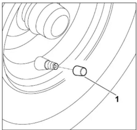
natural_image
Pure technical diagram of a mechanical component with concentric curved lines and labeled point '1' (no text or symbols beyond label)
Remove the cap from the valve (1).
- Inflate the tyres to the following tyre pressures using a suitable air pump.
Front tyres:
0.9 - 1.2 bar
Rear tyres:
0.7 - 1.0 bar
13.26 Opening and closing storage compartment
Opening the storage compartment:

Risk of injury:
Switch off the engine, remove the ignition key and allow the engine to cool down fully before opening the storage compartment.
- Pull the driver's seat adjustment lever upward and move the driver's seat to the frontmost position (towards steering wheel), or fold it forward.
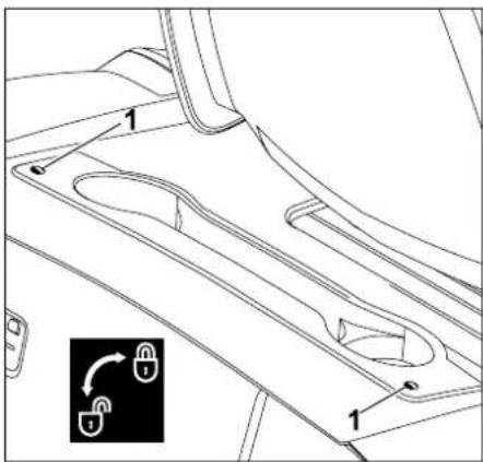
Remove screws (1) by turning through 90° anti-clockwise.
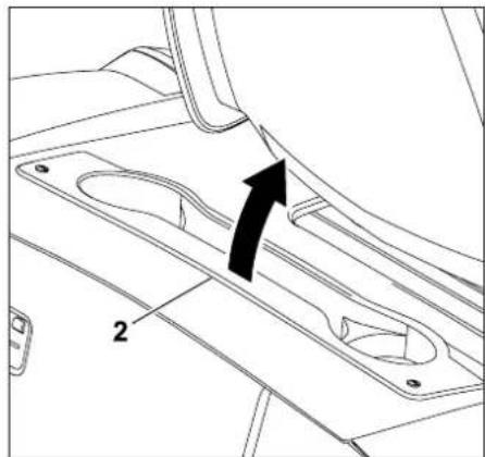
natural_image
Technical line drawing of a mechanical component with mounting holes and a directional arrow (no text or symbols)
Fold the storage compartment (2) up and forward (toward driver's seat).
Closing the storage compartment:
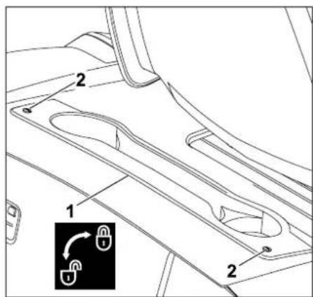
Fold the storage compartment closed: Press the screws (2) downward slightly and hold. Tighten the screws (2) clockwise (approx. 90°).
14. Transport

Risk of injury:
The section "For your safety", especially subsection "Transporting the machine" and subsection "Instructions for safe operation of the machine", must be carefully read and observed.
When loading the machine onto a suitable vehicle or a suitable trailer, it must be ensured that the load is distributed evenly.
When loading the machine, use loading ramps which withstand the weight and are wide enough to be driven over safely. Select a low driving speed when driving over the loading ramps and ensure that the wheels do not drive over the edges of the loading ramps, resulting in the ride-on mower falling to the ground. Handle the vehicle carefully and smoothly when driving on slopes. Do not change speed or direction abruptly.

On public roads, the machine may only be transported by means of a suitable vehicle or trailer. Do not tow!
The following points must be noted when transporting:
15. Standard spare parts
Mowing blade:
6140 702 0100
Blade fastening screw:
9010 345 2430
Spring washer:
0000 702 6600

The fastening elements for the mowing blade (e.g. blade fastening screw) must be replaced when replacing the blade, i.e. when installing the blade. Spare parts are available from a VIKING specialist dealer.
16. Accessories
Additional accessories are available for the machine.
Further information is available from your VIKING specialist dealer, on the internet (www.viking-garden.com) or in the VIKING catalogue.

For safety reasons, only accessories approved by VIKING may be used with the machine.
17. Environmental protection
Clippings should be composted and not disposed of in household waste.
The machine, its packaging and accessories are all produced from recyclable materials and disposed of accordingly.
By disposing of materials separately, and in an environmentally friendly manner, valuable resources can be re-used. For this reason, the machine should be disposed of for recycling at the end of its useful life.
Waste products such as used oil (engine oil, gearbox oil), fuel and batteries must always be disposed of properly. Observe local regulations.
Remove the battery before disposing of the machine.
Do not dispose of the battery with domestic waste, but hand it in to a specialist dealer or at a hazardous waste collection point.
Consult your recycling centre or your specialist dealer for information on the proper disposal of waste products. VIKING recommends VIKING specialist dealers.
18. Minimising wear and preventing damage
Please always observe the following important information for the prevention of damage or excessive wear to your VIKING machine:
1. Wearing parts
Some parts of the VIKING machine are subject to normal wear even when used properly and must be replaced in due time depending on type and duration of use.
These include:
- Mowing blade
- Grass catcher box
- V - b e l t
- Battery
- Tyres, rollers
- Spark plugs
The VIKING machine must be used, maintained and stored with the care described in this instruction manual. Any damage caused by non-compliance with the safety, operating and maintenance instructions is the sole responsibility of the user.
This applies in particular to:
- Improper use of the product.
– Use of fuel and lubricants not approved by VIKING (lubricants, petrol and engine oil, see engine manufacturer's specifications)
– Product modifications not approved by VIKING.
– Use of tools or accessories which are not approved or suitable for the machine, or are of inferior quality.
– Use of the product for sporting or competitive events.
- Resultant damage due to continued use of the product with defective components.
3. Maintenance operations
All operations listed in the section "Maintenance" must be performed regularly.
If these maintenance operations cannot be carried out by the user, a specialist dealer must be commissioned to perform them.
VIKING recommends that you have maintenance operations and repairs performed exclusively by a VIKING specialist dealer.
VIKING specialist dealers regularly attend training courses and are provided with technical information.
If these operations are neglected, faults may arise which are the responsibility of the user.
These include:
– Corrosive and other resultant damage caused by incorrect storage.
– Damage to the machine through the use of inferior-quality spare parts.
– Damage due to untimely or inadequate maintenance or damage due to maintenance or repair work not performed in the workshops of specialist dealers.
We,
VIKING GmbH
Hans Peter Stihl-Strasse 5
declare that the machine,
lawn mower with driver's seat and combustion engine,
Manufacturer's
VIKING
brand:
Type: MR 4082.0
MR 4082.0 K
Serial number 6140
conforms to the following EU guidelines:
2000/14/EC, 97/68/EC, 2004/108/EC,
2006/66/EC, 2006/42/EC
The product has been developed in conformance with the following standards: EN 836, EN 60335
Applicable conformity assessment procedure:
Appendix VIII (2000/14/EC)
Name and address of relevant, named location:
Compilation and storage of technical documentation:
Johann Weiglhofer
VIKING GmbH
The year of manufacture and serial number appear on the identification plate of the machine.
Measured sound power level:
MR 4082.0 99,7 dB(A)
MR 4082.0 K 99,0 dB(A)
Guaranteed sound power level: 100 dB(A)
Langkampfen,
2014-01-02 (YYYY-MM-DD)
VIKING GmbH

Research and Product Development
Manager
- Technical specifications
| MR 4082.0 /MR 4082.0 K: |
| Serial number 6140 |
| Engine, design: 4-stroke combustion engine |
| Fuel tank 6 l |
| Starter Electric start / ignition key |
| Battery type lead / gel |
| Rated voltage: | 12 V |
| Capacity: 17 Ah |
| Tightening torque for blade fastening screw: 65 - 70 Nm |
| Self-propulsion, rear wheels: | infinitely variable forward / infinitely variable reverse |
| Fuel cock: | yes |
| Wheel dimensions, front / tyre pressure: | 13x5.00-6 inch 0.9 - 1.2 bar |
| Wheel dimensions, rear / tyre pressure: | 16x6.50-8 inch 0.7 - 1.0 bar |
| Cutting width: | 80 cm |
| Cutting height: | 35 - 90 mm |
| Grass catcher box capacity: | 250 l |
| MR 4082.0: |
| Engine type B&S | Series 3130 |
| Displacement | 344 ccm |
| Engine output speed | 2700 rpm |
| Nominal output at nominal speed | 6.5 - 2700 kW - rpm |
MR 4082.0:
| In accordance with Directive2000/14/EC:Guaranteed sound power level L_WAd | 100 dB(A) |
| In accordance with Directive2006/42/EC:Sound pressure level at workplace L_pA | 86 db(A) |
| Uncertainty K_pA | 1.2 dB(A) |
| Measurement in accordance with EN 836/EN 1032:Vibration at seat (whole-body acceleration) a_w | 1.0 m/ s^2 |
| Uncertainty K_w | 0.4 m/ s^2 |
| Vibration at steering wheel a_hw | 3.9 m/ s^2 |
| Uncertainty K_hw :Specified vibration characteristic in accordance with EN 12096 | 1.9 m/ s^2 |
| Weight with mowing deck and empty grass catcher box: | 198 kg |
| MR 4082.0 K:Engine typeDisplacementEngine output speedNominal output at nominal speedIn accordance with Directive2000/14/EC:Guaranteed sound power level L_WAd | Kawasaki431 ccm2800 rpm7.7 - 2800 kW - rpm100 dB(A) |
MR 4082.0 K:
| In accordance with Directive2006/42/EC: |
| Sound pressure level at workplace L_pA | 85 dB(A) |
| Uncertainty K_pA | 0.9 dB(A) |
| Measurement in accordance with EN 836/EN 1032: |
| Vibration at seat (whole-body acceleration) a_w | 1.1 m/s ^2 |
| Uncertainty K_w : | 0,6 m/s ^2 |
| Vibration at steering wheel a_hw | 3.5 m/s ^2 |
| Uncertainty K_hw : | 1.8 m/s ^2 |
| Specified vibration characteristic in accordance with EN 12096 |
| Weight with mowing deck and empty grass catcher box: | 204 kg |
20.1 Dimensions
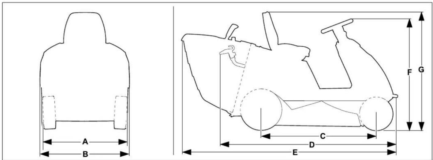
| A = | 8 | 7 | c | m | |
| B = | 9 | 0 | c | m | |
| C = | 1 | 1 | 3 | c | m |
| D = | 1 | 7 | 7 | c | m |
| E = | 2 | 1 | 3 | c | m |
| F = 11 | 0 cm | | |
| G = | 1 | 1 | 8 | c | m |
21. Troubleshooting
If necessary, contact a specialist dealer; VIKING recommends VIKING specialist dealers.
See engine instruction manual.
Fault:
Starter turns, engine does not start.
Possible cause:
- Throttle lever set to MIN position.
- Choke position (throttle lever) is not selected.
- No fuel in tank.
- Fuel cock closed.
- Insufficient flow of fuel.
- Spark plug dirty or damaged.
- Incorrect electrode gap.
- Spark plug socket detached from the spark plug.
– Engine is flooded due to several starting attempts.
- Clogged air filter.
– Battery almost empty.
Remedy:
- Set throttle lever to the choke or MAX position. ( 8.2)
- Set throttle lever to the choke position. ( 8.2)
- Refill fuel tank.
- Open fuel cock. (⇒ 13.14)
- Check fuel filter. (☐)
– Clean or replace spark plug. (11)
- Adjust electrode gap. (✗)
-
Connect spark plug socket; check connection between ignition lead and socket. (✗)
-
Remove spark plug and dry; set throttle lever to MIN position and start several times with spark plug removed; screw in spark plug and connect spark plug socket. (☐)
– Clean the air filter. (☐)
- Check charge state of the battery and charge battery if necessary.
Fault:
Starter not functioning.
Possible cause:
– The safety devices are blocking the starter.
– Battery not or incorrectly connected.
– Battery completely discharged or not sufficiently charged.
- Main fuse (150 A) defective.
– Faulty earth connection to engine or chassis.
- Starter defective.
Remedy:
- Check all the safety devices. (⇒ 10.)
- Check battery connections. (⇒ 13.18)
- Charge the battery. (⇒ 13.18)
- Replace the main fuse. (✗)
- Check the connection cables at the battery and at the chassis. (✗)
- Repair the starter. (✗)
Fault:
Starting problems or deteriorating engine power.
Possible cause:
– Water in fuel tank and carburettor; carburettor is blocked.
- Contaminated fuel tank.
- The air filter is dirty.
- Dirty spark plug.
- Mowing grass which is too long or too wet.
Remedy:
- Empty fuel tank, clean fuel tank, fuel line and carburettor. (✗)
- Clean fuel tank. (✗)
– Clean/replace air filter. (☐)
– Clean spark plug. (☐)
- Adapt cutting level and driving speed to the mowing conditions.
Fault:
Engine overheating.
Possible cause:
- Dirty cooling ribs.
– Engine oil level too low.
- V-belt worn.
Remedy:
- Clean cooling ribs. (☐)
- Check the engine oil level and top up the engine oil if necessary. (⇒ 13.11)
- Replace the V-belt. (✗)
Fault:
Machine does not drive.
Possible cause:
- Gearbox disengaged.
- V-belt (gearbox) detached.
- V-belt (gearbox) worn or defective.
- Missing feather key between rear axle and rear wheels.
Remedy:
- Engage the gearbox (freewheel lever). ( 8.13)
- Fit V-belt (gearbox). (✗)
- Replace V-belt (gearbox). (✗)
- Install feather key. (⇒ 13.9)
Fault: Excessive vibration during operation.
Possible cause:
– Mowing blade imbalance due to incorrect sharpening or damage.
– The blade fastening screw is not fastened tightly.
– The engine mounting is not fastened tightly.
- V-belt is damaged.
– Discharge chute is blocked.
Remedy:
- Re-sharpen the mowing blade and balance or replace the mowing blade. (⇒ 13.7)
– Tighten the blade fastening screw to the specified torque. ( 13.7)
- Tighten engine mounting. (✗)
- Replace the V-belt. (✗)
– Clean the discharge chute. (✗)
Fault: Poor cut, lawn turns yellow after mowing.
Possible cause:
– Mowing blade blunt or worn.
- The driving speed is too fast in relation to the mowing conditions (cutting height, lawn condition).
– Maximum engine speed not set (throttle lever not in MAX position)
– Mowing deck adjustment not OK.
– Discharge chute is blocked.
- The mowing deck is soiled with grass residues (deposits on inside of mowing deck housing).
Remedy:
Fault:
Discharge chute is blocked.
Possible cause:
- Mowing blade wing worn or damaged.
- Mowing grass which is too long or too wet.
– The driving speed is too high in relation to the set cutting height.
– Maximum engine speed not set (throttle lever not in MAX position)
– Level sensor adjusted incorrectly.
Remedy:
- Replace the mowing blade. (⇒ 13.7)
- Mow the lawn in two stages:
- Mowing at the highest cutting level,
- Mowing at the desired cutting height.
- Reduce the driving speed and select a higher cutting height.
- Set the throttle lever to the MAX position. ( 8.2)
- Adjust the level sensor (pull slide out fully). (⇔ 8.14)
Fault:
Grass catcher box not being completely filled.
Possible cause:
– Level sensor incorrectly adjusted.
– Cutting height set too low.
- Grass is excessively damp and consequently too heavy to be transported through the discharge chute in the grass catcher box.
– Mowing blade is blunt or worn.
- Grass is too high.
– Air holes in the grass catcher box blocked (no air flow in grass catcher box).
- Discharge chute or mowing deck (inside) soiled through deposited grass residues (residue from last mowing operation).
Remedy:
- Adjust level sensor. ( 8.14)
- Set a higher cutting height.
- Wait until the lawn is dry.
- Sharpen or replace the mowing blade.
(⇒ 13.7)
– Mow the lawn in two stages:
- Mowing at the highest cutting level,
- Mowing at the desired cutting height.
– Clean the grass catcher box (clean air holes).
– Clean discharge chute or inside of mowing deck.
Fault:
Level sensor (grass catcher box) does not respond properly.
Possible cause:
– Level sensor (grass catcher box) soiled through grass residues.
– Level sensor (grass catcher box) incorrectly adjusted.
- Driving speed too high.
Remedy:
– Clean the level sensor and check for ease of movement.
- Adjust level sensor (grass catcher box).
(⇒ 8.14)
- Adapt driving speed to the mowing conditions (reduce driving speed).
Fault:
Mowing blade does not switch on / does not turn.
Possible cause:
– The safety devices are preventing activation of the mowing blade.
– V-belt (mowing deck) worn, detached or defective.
Remedy:
- Check whether all the safety requirements for activation of the mowing blade are met. (⇒ 10.)
- Check V-belt (mowing deck) and replace if necessary. (✗)
Fault:
Engine cuts out when mowing deck is activated.
Possible cause:
- User not sitting or not properly positioned on driver's seat.
- Seat switch or wiring is defective.
- Grass catcher box switch not actuated or defective.
Remedy:
- Sit on the driver's seat or change seat position.
- Repair/replace seat switch or wiring.
(✗)
- Install grass catcher box or deflector (not included in standard equipment), or repair/replace grass catcher box switch. (✗)
Fault:
Engine cuts out when user leaves driver's seat.
Possible cause:
– Parking brake not engaged.
– Mowing deck engaged (safety device).
Remedy:
- Engage the parking brake before leaving the driver's seat. ( 8.9)
- Disengage the mowing deck before leaving the driver's seat. (⇒ 8.3)
22. Service schedule
22.1 Handover confirmation
Model:
Serial number:

Date:


natural_image
Simple line drawing of a mechanical component with a cylindrical top and rectangular base (no text or symbols)
Next service
Date: ____ ____ ____ ____ ____
22.2 Service confirmation
Please hand this instruction manual to your VIKING specialist dealer in the case of maintenance work. He will confirm the service operations performed in the pre-printed boxes.

Service performed on

Next service date

Chère cliente, cher client,
Attention!
Marche avant :
Arrêt :
natural_image
Technical line drawing of a mechanical component with labeled parts (no text or symbols)
natural_image
Technical line drawing of a mechanical component with a lever and pin (no text or symbols)
natural_image
Line drawing of a truck's cab with a lever and upward arrow indicating motion (no text or symbols)
natural_image
Illustration of a hand pressing down on a mechanical component with an arrow indicating force direction (no text or symbols)
natural_image
Technical line drawing of a mechanical component with no visible text or symbols
natural_image
Mechanical assembly diagram showing a lever mechanism with pulleys and gears (no text or labels)
natural_image
Line drawing of a hand pressing down on a curved mechanical component with an arrow indicating motion (no text or symbols)
natural_image
Line drawing of a person pushing a vehicle with a numbered arrow indicating direction (no text or symbols present)
natural_image
Line drawing of a person pushing a vehicle wheel with a labeled component (no text or symbols present)
Étape 1 :
natural_image
Illustration of a hand holding a tool with a numbered label '5' and a curved arrow below (no text or symbols on the diagram itself)
Étape 1 :
natural_image
Technical line drawing of a mechanical device with internal components and a directional arrow indicating motion (no text or symbols present)
natural_image
Technical line drawing of a mechanical assembly with no visible text or symbols
Étape 1 :
Étape 4 :
natural_image
Technical line drawing of a mechanical component with labeled parts (no text or symbols present)
Distance A= 10 mm.
natural_image
Technical line drawing of a vehicle engine compartment with internal components and a close-up inset showing internal parts (no text or symbols)
natural_image
Technical line drawing of a mechanical assembly with no visible text or symbols
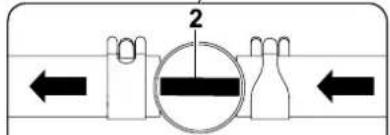
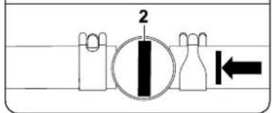
natural_image
Diagram of a mechanical component with concentric curved lines and two labeled parts (1), no readable text or symbols present.
natural_image
Technical line drawing of a car interior component with labeled parts (no text or symbols)
natural_image
Technical line drawing of a mechanical component with labeled parts (no text or symbols)
2000/14/EC, 97/68/EC, 2004/108/EC, 2006/66/EC, 2006/42/EC
MR 4082.0 K 99,0 dB(A)
| A = | 8 7 c |
| B = | 9 0 c |
| C = 113 cm |
| D = 177 cm |
| E = 213 cm |
| F = 110 cm |
| G = 118 cm |
m
m
natural_image
Simple line drawing of a mechanical component with a cylindrical top and rectangular base (no text or symbols)
Prochain entretien
Date: ____ ____ ____ ____ ____
natural_image
Technical line drawing of a mechanical component with no visible text or symbols


Opgelet!
Stoppen:
natural_image
Technical diagram of a mechanical component with labeled parts (no readable text or symbols)
natural_image
Technical line drawing of a mechanical component with a labeled lever and directional arrow (no text or symbols present)
natural_image
Line drawing of a truck's cab with a lever and exhaust pipe, showing motion direction (no text or symbols)
natural_image
Illustration of a hand pressing down on a curved mechanical component with an arrow indicating motion (no text or symbols)
natural_image
Technical line drawing of a mechanical component with a curved internal channel and labeled part '1' (no text or symbols beyond the label)
natural_image
Mechanical assembly diagram showing a lever mechanism with pulleys and rotating parts (no text or labels)
natural_image
Line drawing of a hand pressing down on a curved mechanical component with an arrow indicating motion (no text or symbols)
natural_image
Line drawing of a person pushing a vehicle with a directional arrow (no text or symbols)
natural_image
Line drawing of a person pushing a vehicle wheel with a labeled component (no text or symbols present)
Stap 1:
Stap 1:
natural_image
Technical line drawing of a mechanical device with internal components and a directional arrow (no text or symbols)
natural_image
Technical line drawing of a mechanical device with internal components and directional arrows (no text or symbols)
Stap 1:
Stap 4:
natural_image
Technical line drawing of a mechanical component with labeled parts (no text or symbols present)
Vooras: A = minstens 200 mm
Achteras: B = minstens 120 mm
Wiel demonteren
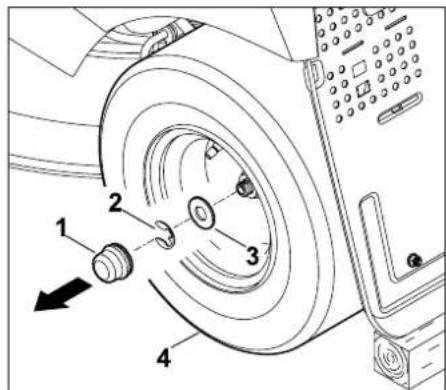
natural_image
Technical line drawing of a car interior showing engine compartment and internal components (no text or symbols)
natural_image
Technical line drawing of a mechanical assembly with no visible text or symbols
natural_image
Pure technical diagram of a mechanical component with concentric curved lines and a labeled arrow (no text or symbols)
natural_image
Technical line drawing of a car interior panel with lock icons indicating rotation and locking mechanism (no text or symbols)
Draai de schroeven (1) 90° linksom.

natural_image
Technical line drawing of a mechanical component with mounting holes and a directional arrow (no text or symbols)
Opbergvak (1) dichtklappen.
2000/14/EC, 97/68/EC, 2004/108/EC,
2006/66/EC, 2006/42/EC
MR 4082.0 K 99,0 dB(A)
| A = | 8 7 c |
| B = | 9 0 c |
| C = 113 cm |
| D = 177 cm |
| E = 213 cm |
| F = 110 cm |
| G = 118 cm |
m
m
21. Defectopsporing
natural_image
Simple line drawing of a mechanical component with a cylindrical top and rectangular base (no text or symbols)
natural_image
Technical line drawing of a mechanical component with no visible text or symbols


Attenzione!
Arresto:
natural_image
Technical line drawing of a mechanical component with labeled parts (no text or symbols)
natural_image
Technical line drawing of a mechanical component with a lever and pin (no text or symbols)
natural_image
Line drawing of a truck's cab with a lever and exhaust pipe, showing no text or symbols
natural_image
Illustration of a hand pressing down on a curved mechanical component with an arrow indicating motion (no text or symbols)
natural_image
Technical line drawing of a mechanical component with no visible text or symbols
natural_image
Mechanical assembly diagram showing a lever mechanism with pulleys and gears, no text or symbols present
natural_image
Illustration of a hand pressing down on a mechanical component with an arrow indicating motion (no text or symbols)
natural_image
Line drawing of a person pushing a vehicle with a directional arrow (no text or symbols)
natural_image
Line drawing of a person pushing a large mechanical component next to a vehicle (no text or symbols)
natural_image
Line drawing of a cart loaded with a black cylindrical container labeled 'kg' (no other text or symbols)
Passaggio 1:
Passaggio 1:
natural_image
Technical line drawing of a mechanical device with internal components and a directional arrow indicating motion (no text or symbols)
natural_image
Technical line drawing of a mechanical device with internal components and directional arrows (no text or symbols)
Passaggio 1:
Passaggio 4:
natural_image
Illustration of a hand holding a tool with a numbered label '5' and a spiral pattern, no text or symbols present.
natural_image
Technical line drawing of a mechanical component with labeled parts (no text or symbols present)
Distanza A= 10 mm.
natural_image
Technical diagram of a vehicle's internal components, showing parts like engine, dashboard, and gear assembly (no text or labels)
natural_image
Technical line drawing of a mechanical assembly with no visible text or symbols
natural_image
Diagram of a mechanical component with concentric curved lines and two labeled parts (1), no readable text or symbols present.
natural_image
Technical line drawing of a mechanical component with labeled parts (no text or symbols)
2000/14/EC, 97/68/EC, 2004/108/EC,
2006/66/EC, 2006/42/EC
MR 4082.0 K 99,0 dB(A)
| A = | 8 7 c |
| B = | 9 0 c |
| C = 113 cm |
| D = 177 cm |
| E = 213 cm |
| F = 110 cm |
| G = 118 cm |
m
m
natural_image
Technical line drawing of a mechanical component with no visible text or symbols

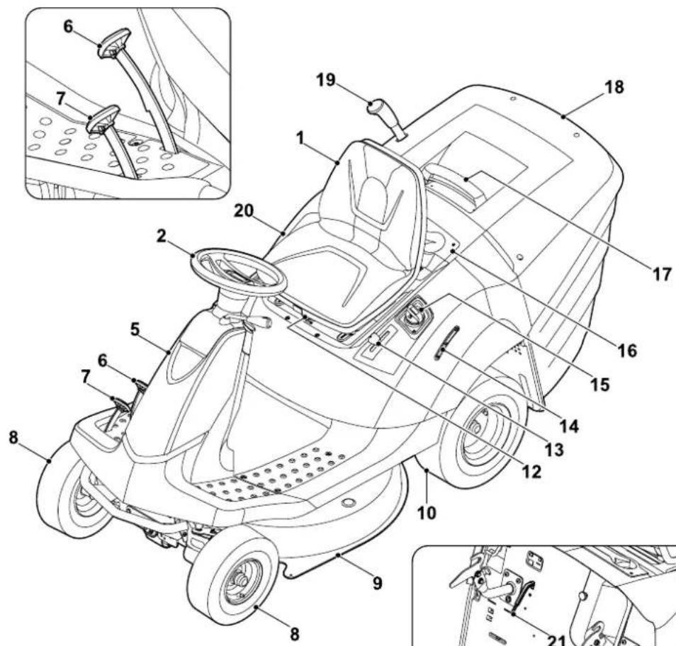
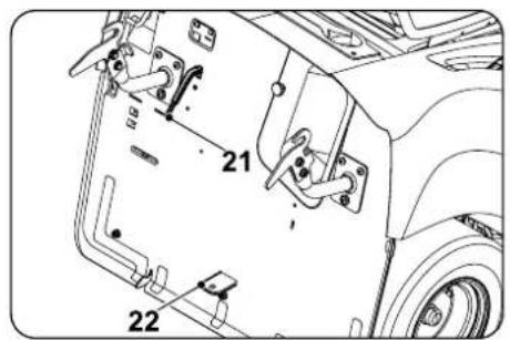
¡Atención!
natural_image
Technical line drawing of a mechanical component with labeled parts (no text or symbols)
natural_image
Technical line drawing of a mechanical component with a lever and pin (no text or symbols)
natural_image
Technical line drawing of a truck's cab with a lever and load, showing no text or symbols
natural_image
Illustration of a hand pressing down on a mechanical component with an arrow indicating motion (no text or symbols)
natural_image
Technical line drawing of a mechanical component with no visible text or symbols
natural_image
Mechanical assembly diagram showing a lever mechanism with pulleys and gears (no text or labels)
natural_image
Illustration of a hand pressing down on a curved mechanical component with an arrow indicating motion (no text or symbols)
natural_image
Line drawing of a person pushing a vehicle with a directional arrow (no text or symbols)
natural_image
Line drawing of a person pushing a large saw blade with a labeled component (no text or symbols present)
natural_image
Line drawing of a cart with a black weight labeled 'kg' on top, next to a vehicle (no text or symbols beyond the label)
Paso 1:
Paso 1:
natural_image
Technical line drawing of a mechanical device with internal components and a directional arrow indicating motion (no text or symbols)
natural_image
Technical line drawing of a mechanical device with internal components and directional arrows (no text or symbols)
Paso 1:
Paso 4:
natural_image
Technical line drawing of a mechanical component with labeled parts (no text or symbols present)
A = Grosor de la cuchilla
B = Anchura de la cuchilla
Grosor de la cuchilla A:
La distancia A = 10 mm.
natural_image
Technical line drawing of a vehicle chassis with wheels and a labeled block (no text or symbols)
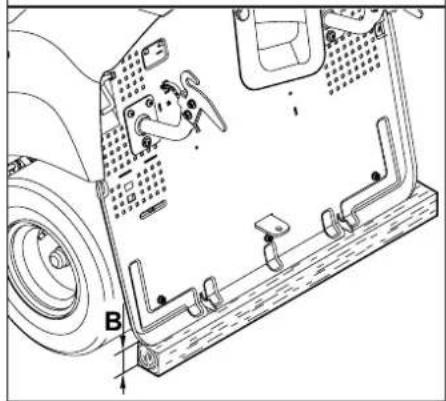
natural_image
Technical line drawing of a vehicle chassis frame with labeled components (no text or symbols)
natural_image
Technical diagram of a car interior showing engine compartment and internal components (no text or labels)
natural_image
Technical line drawing of a mechanical assembly with labeled component '1' (no text or symbols beyond label)
natural_image
Diagram of a mechanical component with concentric curved lines and a labeled arrow pointing to a cylindrical feature (no text or symbols present)
natural_image
Technical line drawing of a mechanical component with a black arrow indicating direction (no text or symbols)
2000/14/EC, 97/68/EC, 2004/108/EC,
2006/66/EC, 2006/42/EC
MR 4082.0 K 99,0 dB(A)
2014-01-02 (AAAA-MM-DD)
VIKING GmbH

Director del Departamento de
| A = | 8 7 c |
| B = | 9 0 c |
| C = 113 cm |
| D = 177 cm |
| E = 213 cm |
| F = 110 cm |
| G = 118 cm |
m
m
natural_image
Simple line drawing of a mechanical component with a cylindrical top and rectangular base (no text or symbols)
Próxima revisión
Fecha: ____ ____ ____ ____ ____
4.3 Transporte do tractor corta-relva
Atenção!
Parar:
Carregue no pedal do travão (1).
natural_image
Technical line drawing of a mechanical component with labeled parts (no text or symbols)
natural_image
Technical line drawing of a mechanical component with a labeled part (1), showing internal parts and motion arrows (no text or symbols)
natural_image
Technical line drawing of a truck's cab with a lever and load, showing no text or symbols
natural_image
Line drawing of a hand pressing down on a curved mechanical component with an arrow indicating motion (no text or symbols)
natural_image
Technical line drawing of a mechanical component with no visible text or symbols
natural_image
Mechanical assembly diagram showing a lever mechanism with labeled parts and directional arrows (no text or symbols)
natural_image
Illustration of a hand pressing down on a curved mechanical component with an arrow indicating force (no text or symbols)
natural_image
Line drawing of a person pushing a vehicle with a directional arrow (no text or symbols)
Remova a cesta de recolha de relva (2).
natural_image
Line drawing of a person pushing a vehicle wheelbarrow with a tool, no text or symbols present
Vista geral dos componentes no mecanismo de corte no estado montado
Passo 1:
Passo 1:
natural_image
Technical line drawing of a mechanical device with internal components and a directional arrow indicating motion (no text or symbols present)
natural_image
Technical line drawing of a mechanical device with labeled components and an upward arrow indicating motion (no text or symbols present)
Passo 1:
Passo 4:
natural_image
Technical line drawing of a mechanical component with labeled parts (no text or symbols present)
13.9 Substituir as rodas
natural_image
Technical line drawing of a vehicle chassis with wheels and a box labeled A (no text or symbols beyond label)

natural_image
Technical line drawing of a vehicle chassis frame with mounting brackets and structural components (no text or symbols)
Solte e desenrosque os parafusos (5).
natural_image
Technical diagram of a car interior showing engine compartment and internal components (no text or labels)
natural_image
Technical line drawing of a mechanical assembly with no visible text or symbols
natural_image
Diagram of a mechanical component with concentric curved lines and a labeled arrow pointing to a cylindrical feature (no text or symbols present)
Desenrosque a tampa da válvula (1).
natural_image
Technical line drawing of a mechanical component with an arrow indicating direction (no text or symbols)
2000/14/EC, 97/68/EC, 2004/108/EC,
2006/66/EC, 2006/42/EC
MR 4082.0 K 99,0 dB(A)
2014-01-02 (AAAA-MM-DD)
VIKING GmbH

| A = | 8 7 c |
| B = | 9 0 c |
| C = 113 cm |
| D = 177 cm |
| E = 213 cm |
| F = 110 cm |
| G = 118 cm |
m
m
natural_image
Simple line drawing of a mechanical component with a cylindrical top and rectangular base (no text or symbols)
natural_image
Product lineup of five lawn lawn tools including a grass lawn, manual lawn, and trowler (no visible text or labels)

0478 193 9901 A

