Summit 27+ - Air Conditioning SUNTEC - Free user manual and instructions
Find the device manual for free Summit 27+ SUNTEC in PDF.


| Brand | Suntec |
| Model | Summit 27+ |
| Product type | Monobloc portable air conditioner |
| Use | Indoor only |
| Power supply | 220-240 V ~ 50 Hz |
| Refrigerant | R410A |
| Operating modes | Cooling, dehumidification, ventilation, sleep |
| Temperature range in cooling mode | 17°C to 30°C |
| Ambient temperature display | 10°C to 35°C |
| Remote control | Included |
| Exhaust hose length | 28 cm to 150 cm |
| Fan speeds | Low and High |
| Air filter | Washable with warm water (40°C) and mild detergent |
| Filter cleaning | Every 2 weeks |
| Anti-freeze function | Yes (code E4) |
| Full water tank alarm | Yes (FL display) |
| Compressor protection | 3-minute delay on startup |
| Timer | 1 to 24 hours |
| Spare parts available | Air-Block Klima-Sail, Air-Extension-Kit, Window-Kit, Wall-Kit |
| Warranty | 24 months |
Frequently Asked Questions - Summit 27+ SUNTEC
User questions about Summit 27+ SUNTEC
0 question about this device. Answer the ones you know or ask your own.
Ask a new question about this device
Download the instructions for your Air Conditioning in PDF format for free! Find your manual Summit 27+ - SUNTEC and take your electronic device back in hand. On this page are published all the documents necessary for the use of your device. Summit 27+ by SUNTEC.
USER MANUAL Summit 27+ SUNTEC
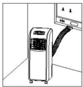
Fig. 1 Fig.2
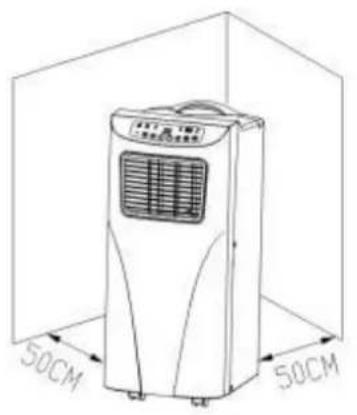
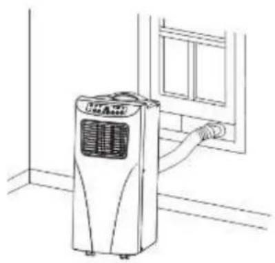
Fig. 3 Fig. 4
SEHR WICHTIG!
![graph TD A["Device 1"] --> B["Processing Unit"] C["Device 2"] --> D["Processing Unit"] style A fill:#f9f,stroke:#333 style C fill:#bbf,stroke:#333 style B fill:#dfd,stroke:#333 style D fill:#dfd,stroke:#333](/content/2026/02/397001/images/42cf3cbd160558d689eb98708d84a0c55d7efafd2ff8fd4959ed05d7a5b67db0.jpg)
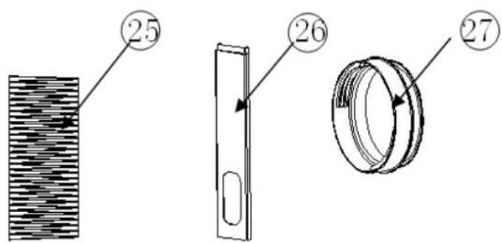
Abb. 1
Abb. 7
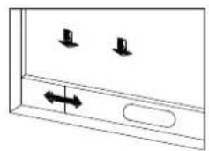
Abb. 8
Abb. 9
Abb. 10
© 2016 KLIMATRONIC® SUMMIT plus
SUNTEC WELLNESS GMBH / HOLZSTRASSE 2 / 40221 DÜSSELDORF / DEUTSCHLAND
Fig. 1 Fig.2
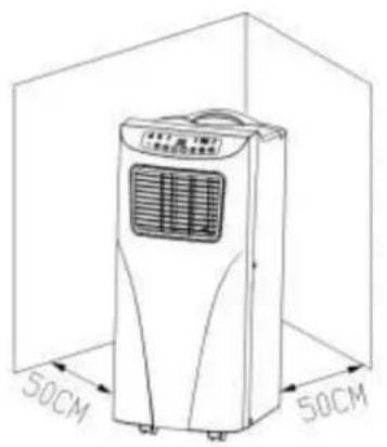
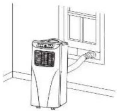
Fig. 3 Fig. 4
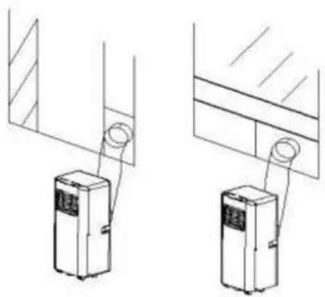
VERY IMPORTANT!
Please do not install or use your local mobile air conditioner before you have carefully read this manual. Please keep this instruction manual for an eventual product warranty and for future reference.
Safety instruction
This appliance can be used by children aged from 8 years and above and persons with reduced physical, sensory and mental capabilities or lack of experience and knowledge if they have been given supervision or instruction concerning use of the appliance in a safe way and understand the hazards involved. Cleaning and user maintenance shall not be made by children without supervision.
- Do not use the unit outdoor.
- Do not use the unit if the power cord was damaged, if it seems to be defective.
- The unit may not be connected to a defective outlet. Please make sure before using that the unit has been properly installed.
- Do not use the unit near open fire sources.
- Do not expose the unit to direct sunlight.
- Please turn off the power before you unplug the power cord.
- Before cleaning the unit, turn it off and unplug the power cord.
- Before replacing the unit please make sure that the power cord is not plugged in and move it slowly.
- Please clean the unit only on the way as described in this manual.
- Connect the unit to a properly grounded electrical outlet (220-240V, 50 Hz).
- Do not let your children play with the unit.
- The unit should not be used without supervision. Please turn off the unit even if you leave the room for only a short time.
- Unplug the unit from the socket when you do not use it. Please do not pull on the cord.
- Do not use the unit on a place where it could be splashed with an oil or water.
-
Do not use the unit near bath, shower or swimming pool.
-
Never insert fingers, pencils or other objects into the unit if the power cord is plugged, and especially not during operation.
- This local air conditioner must be stored and transported upright, otherwise you may cause irreparable compressor damage. In case of doubt let the unit rest for at least 24 hours before you start it.
- Do not cover the unit and make sure that the air inlet and outlet are not blocked.
- Please make sure that the unit stands upright.
- Please use only the spare parts and accessories offered by the manufacturer to avoid damage to the device.
- You should never repair your local air conditioner by yourself. Please contact your dealer if the unit needs to be repaired.
- In case of breakdown turn off the unit (only by the Power button located on the control panel) and contact your dealer.
- In case of power cord damage please turn off the unit and unplug it to avoid fire hazard.
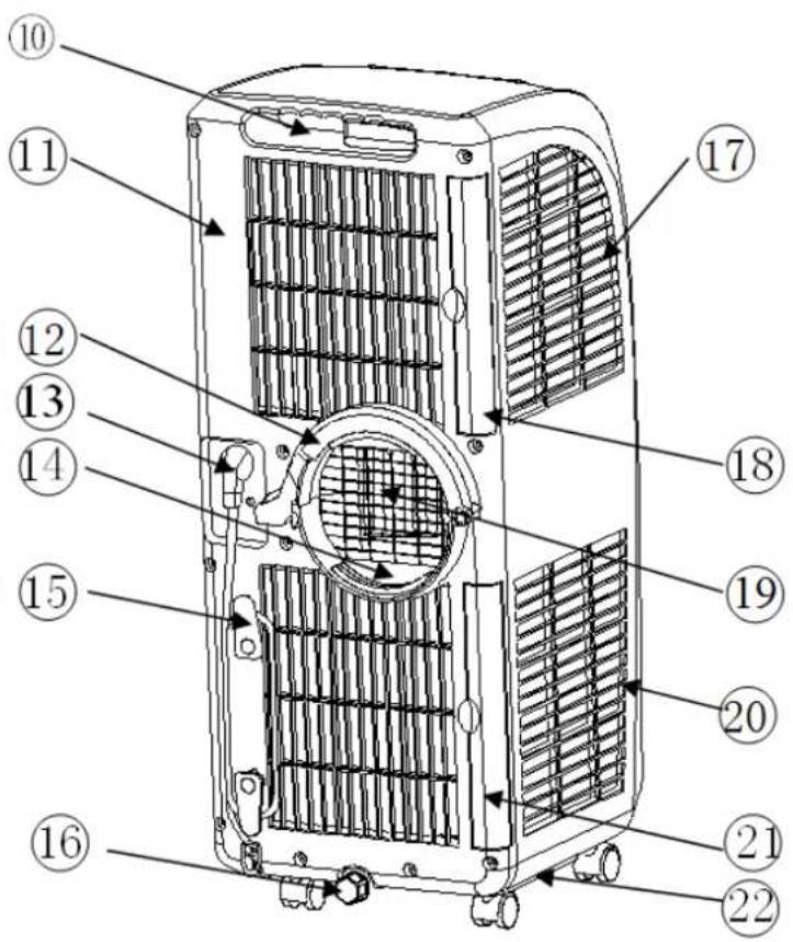
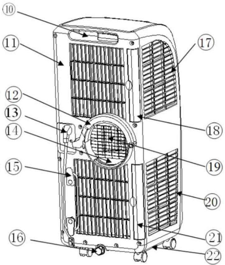
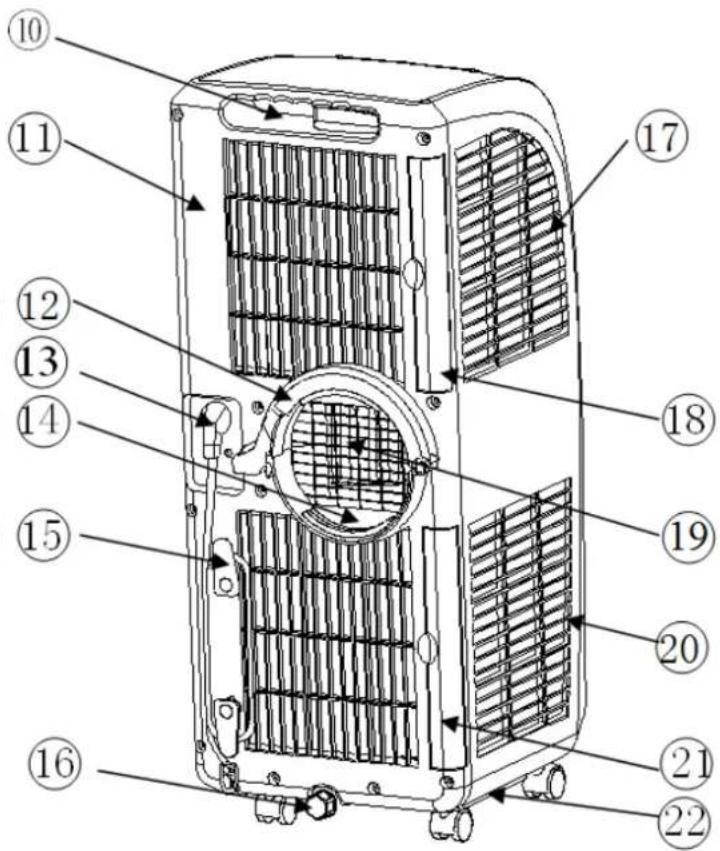
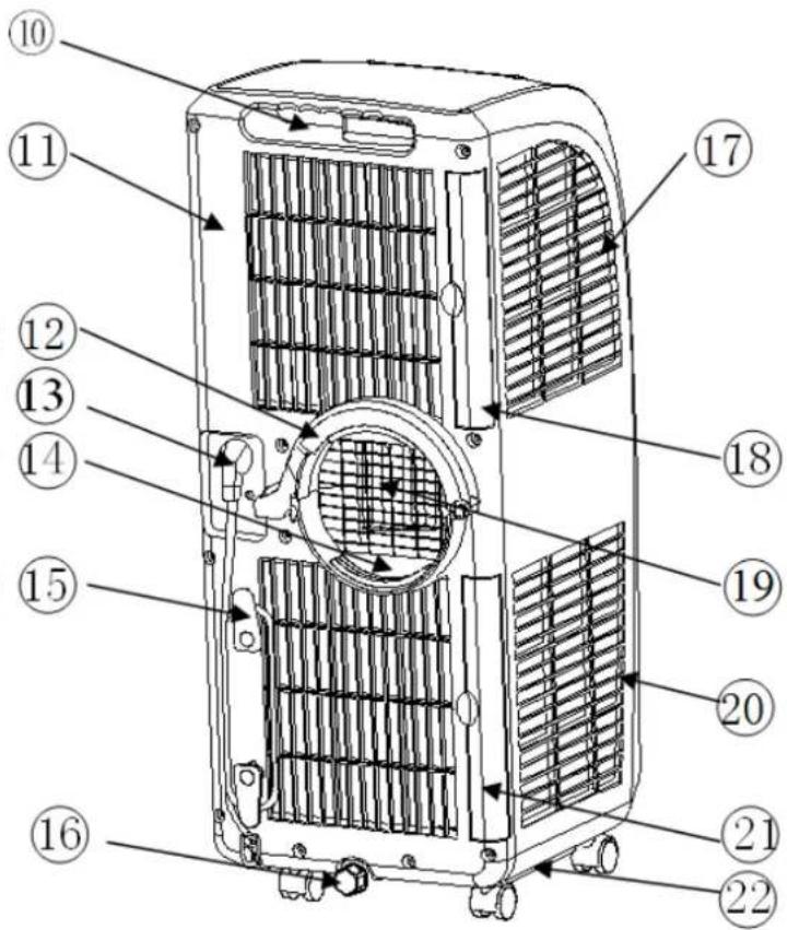
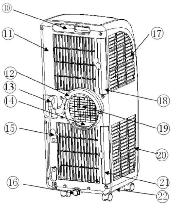
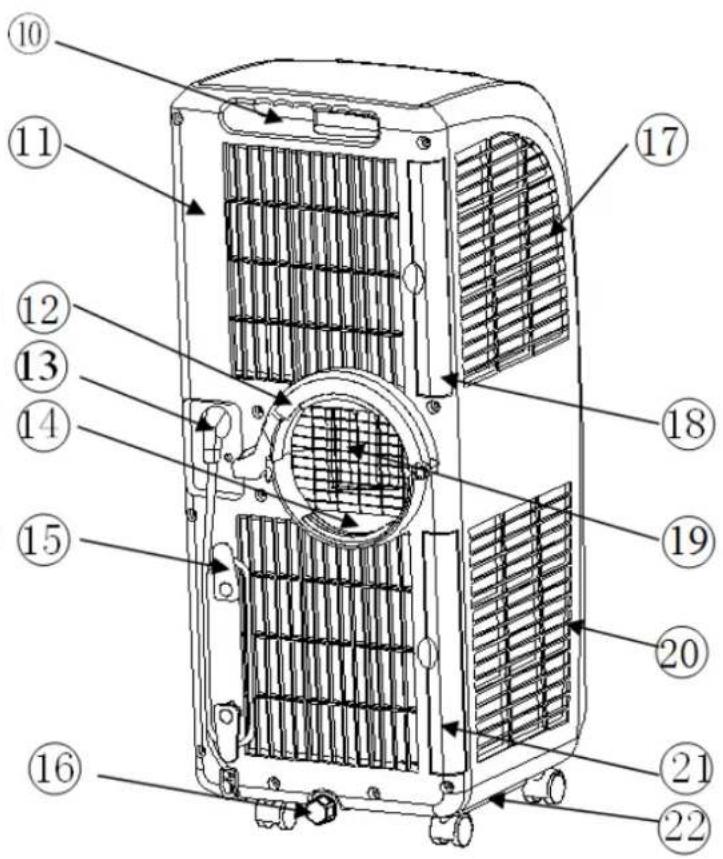
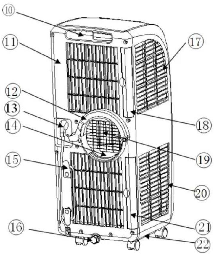
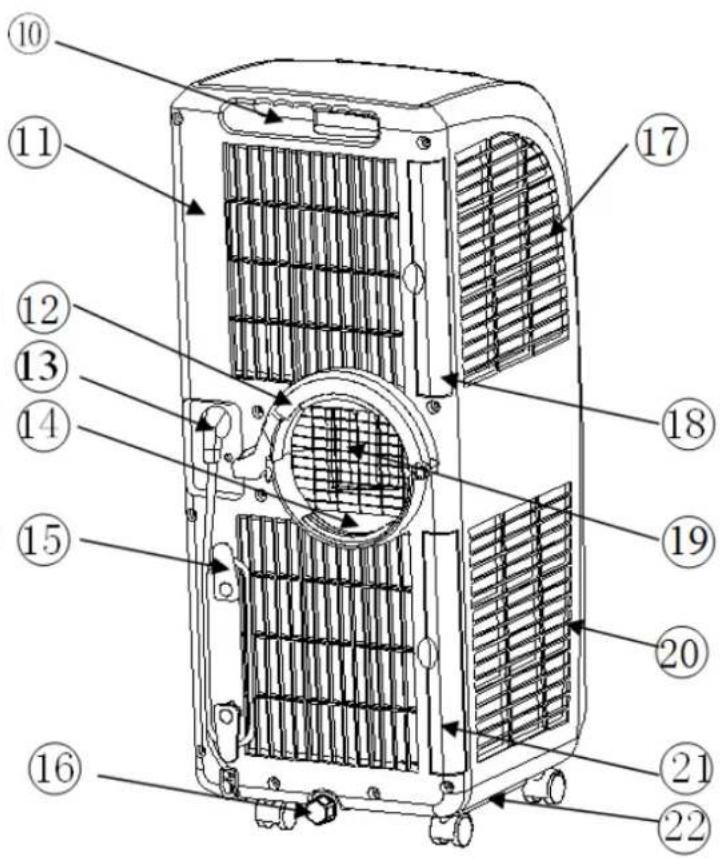
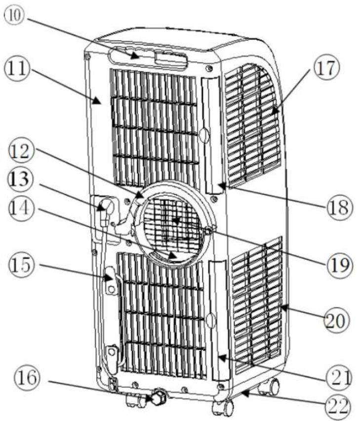
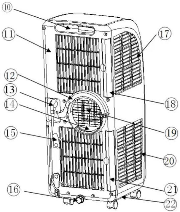
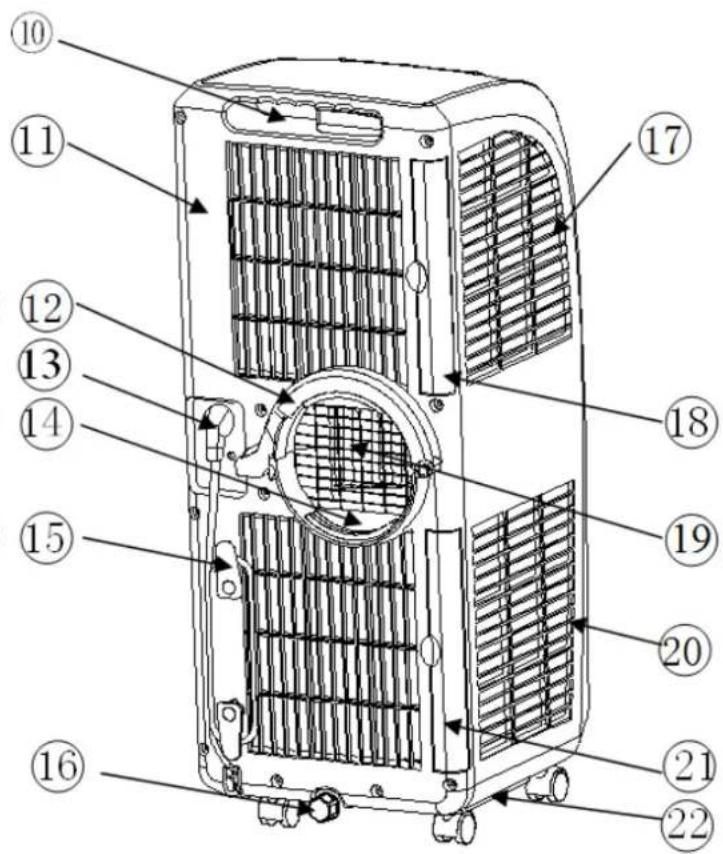
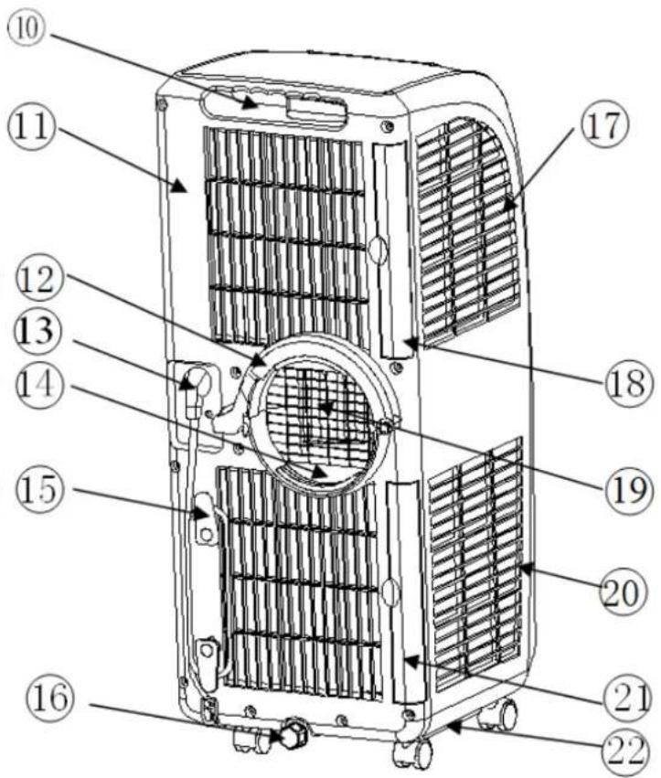
Components
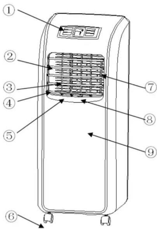

![graph TD A["Device 23"] --> B["Processing Unit"] C["Device 24"] --> B style A fill:#f9f,stroke:#333 style B fill:#bbf,stroke:#333 note1["②3"] --> A note2["②4"] --> C](/content/2026/02/397001/images/d433e68feca82be4646aa23c6504ad423be659ae82d7646c5ed33efce8048e1f.jpg)
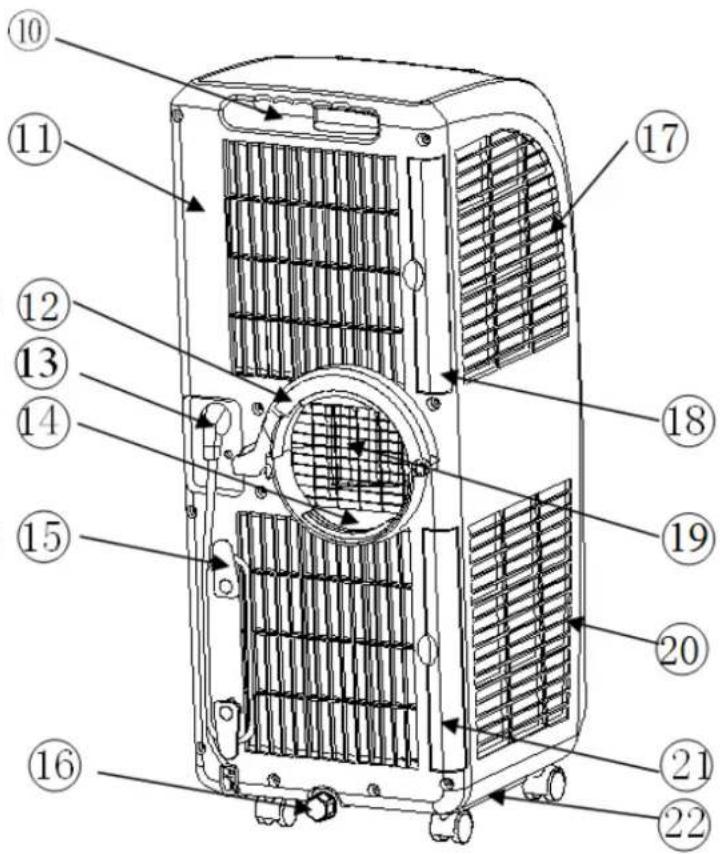
-
Control panel
-
Horizontal louver
-
Vertical louver
-
Air outlet frame
-
Vertical louver connecting lever
-
Caster
-
Horizontal louver connecting lever
-
Main vertical louver
-
Front shell
-
Handle
-
Back shell
-
C-shaped buckle
-
Power cord
-
Lower air duct bottom
-
Wire-winding post
-
Drain cap
-
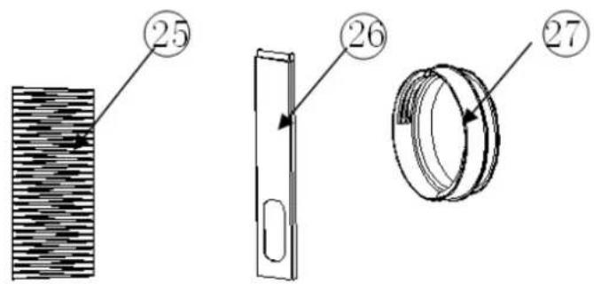
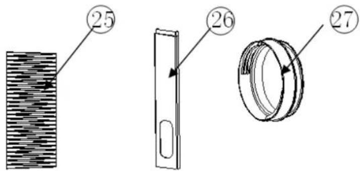
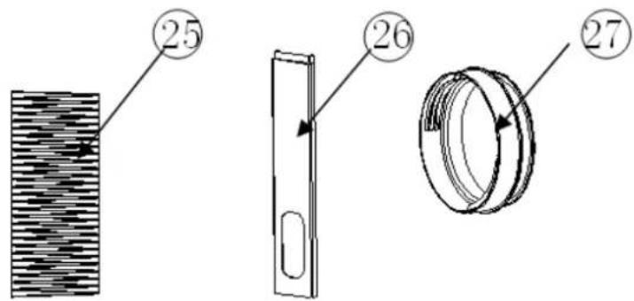
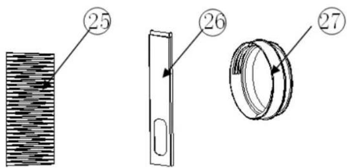
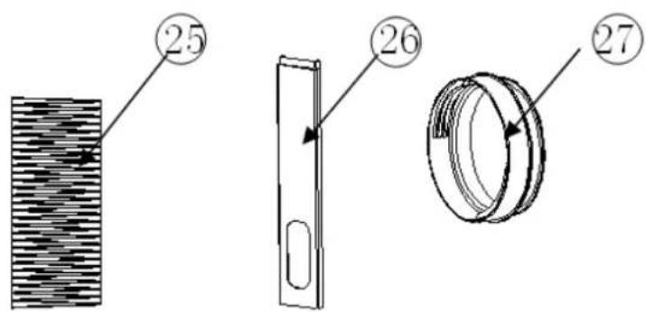
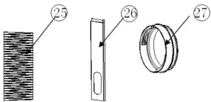
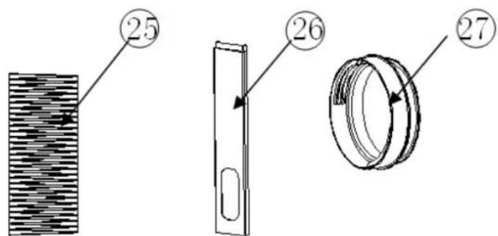
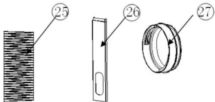
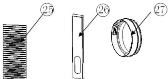
Evaporator filter mesh
-
Evaporator filter frame
-
Outlet fine mesh
-
Condenser filter mesh
-
Condenser filter frame
-
Base plate (Right side: remote control storage area)
-
Remote control
-
Exhaust hose outer connector
-
Exhaust hose exhaust hose snap
-
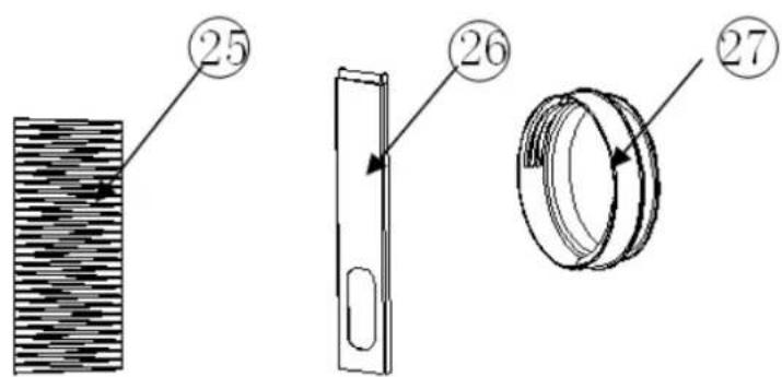
Window sealing board assembly
-
Round connector
Installation
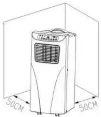
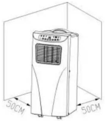
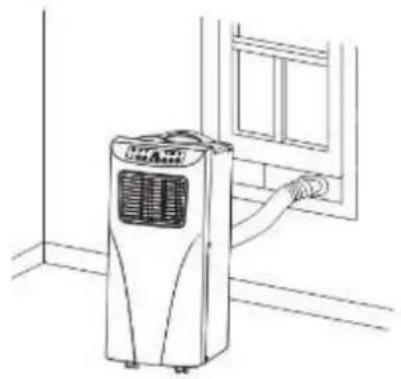
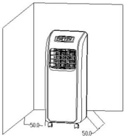
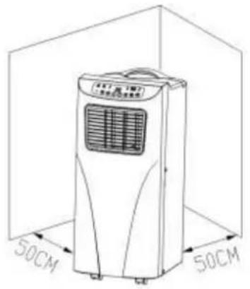
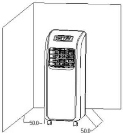
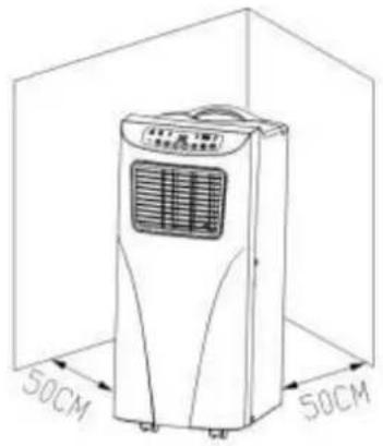
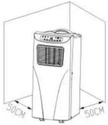
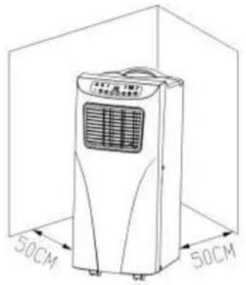
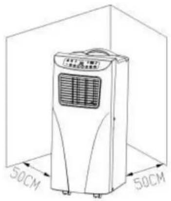
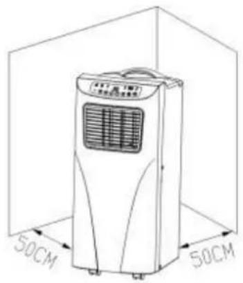
The unit should stand 50 cm away from other objects because they can strongly influence performance of the device (The unit should stand 50 cm away from other objects because they can strongly influence performance of the device (Fig. 1).
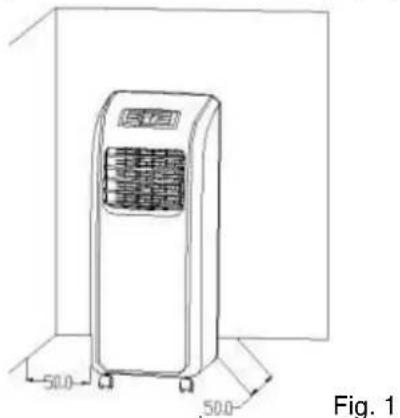
Warning: Before using this unit, you should let it stand straight for at least 24 hours.
The unit can be easily moved between rooms, but please note the following:
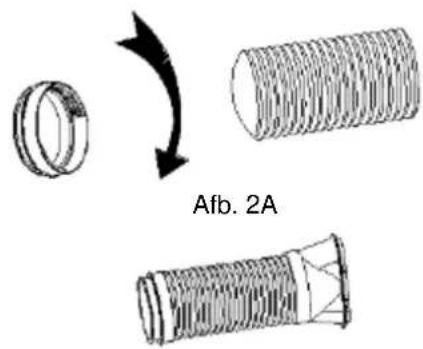
Assembly of the heat exhausts outer connector (Figure 1A), heat exhaust hose short connector (Figure 2A), and the heat exhausts outer connector and heat exhaust hose short connector (Figure 1, Figure 2).
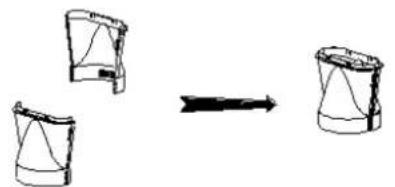
Fig. 1A
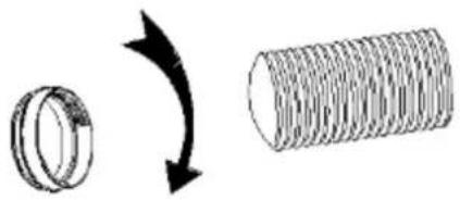
Fig. 2A
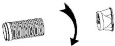
Fig. 1
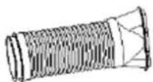
Fig. 2
- Dismantle the two pieces of the heat exhaust hose outer connector; these two pieces are equal in form.
- Hold each piece with one hand, put the joint of one piece toward the other one's groove, and press them to make them snap tightly (Figure 1A).
Take out the heat exhaust hose and the round connector, pull the few turns of the hose end apart, and screw it counter clockwise into the whorl side of the round connector to form heat exhaust hose assembly A (Figure 2A). - Pull the few turns at the other end of the heat exhaust hose apart, screw the round end of the heat exhaust hose outer connector counter clockwise into the heat exhaust hose to form the heat exhaust hose assembly (Figure 1).
– Figure 2 shows the final assembled exhaust hose.
Note : When press the two pieces of the outer connector, exert the strength from small to big, so as not to cause any damage to it. The joint must be pressed into position. The heat exhaust hose
and the two sides' connectors should be screwed into position, and at least be screwed three turns.
Installation of the C-shaped buckle of the heat exhaust hose and unit.
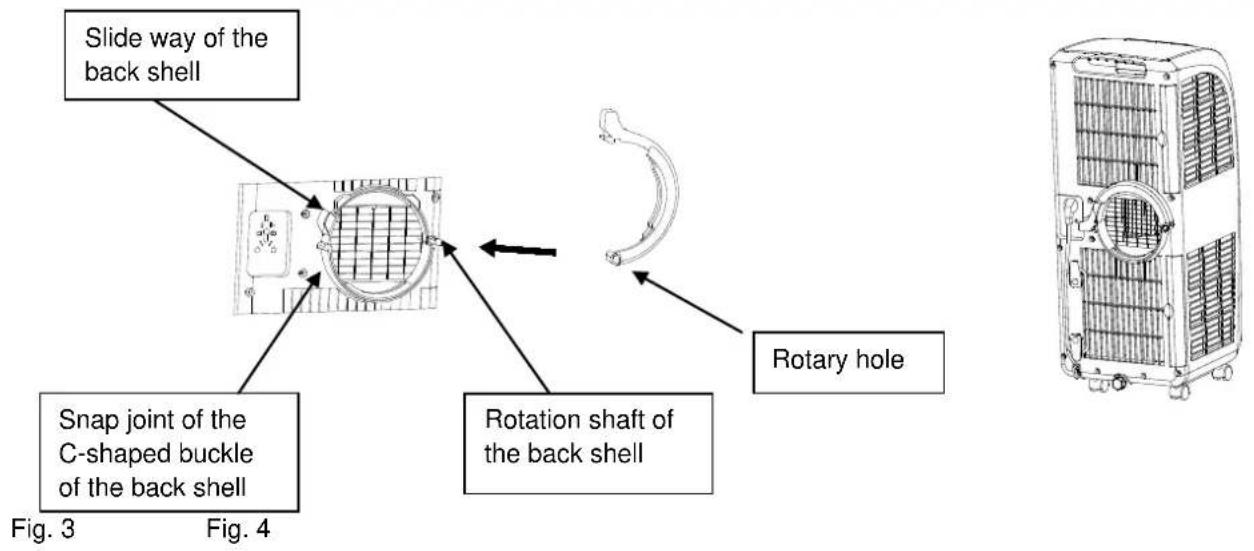
- Take out the C shape buckle of the heat exhaust hose and remove the plastic bag.
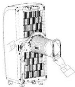
- Point the rotary hole at the end of the heat exhaust hose snap toward the rotation shaft of the back shell and slide it onto the back shell in accordance with the snap joint direction of the rotation shaft on the back shell (as shown in Figure 3).
Note: When the end snap joint at the end of the rotation shaft of the back shell sticks out of the snap, it means that the heat exhaust hose snap has been slid into place. - Rotate the C shape buckle of the heat exhaust hose that is slid into place counterclockwise to clip the snap joint of the C shape buckle of the back shell successfully through the guide of the slide way of the back shell (as shown in Figure 4).
Note: Do not rotate the C shape buckle of the heat exhaust hose if it is not slid into place as this may damage the rotation shaft of the back shell and the C shape buckle of the heat exhaust hose.
Installation of the heat exhaust hose assembly and unit (Fig. 5 and Fig. 6)
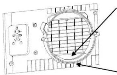
- Hold the end handle of the C shape buckle of the heat exhaust hose with the left hand and the heat exhaust hose short connector with the right hand, put one end of the heat exhaust hose that is pulled apart onto the snap of the lower air duct bottom, press the C shape buckle of the heat exhaust hose with the left hand by force so that the C shape buckle of the heat exhaust hose clips the snap joint of the back shell (as shown in Figure 5).
Note: The round connector must be put on the step inside the bottom of the lower air duct (as shown in Figure 5). The C shape buckle that clips the heat exhaust hose assembly must clip the back shell and the round connector firmly
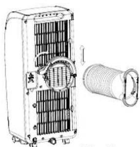
Fig. 5
Position of lower air duct bottom step
Lower air
duct bottom
joint
Fig. 6
- Hold the unit with one hand and the heat exhaust hose short connector with another hand; or both people cooperate with one person holding the unit and the other person pulling the heat exhaust hose
to prolong the heat exhaust hose gently.
Note: Do not separate the heat exhaust hose assembly from the unit. Do not tilt the unit when pulling apart the heat exhaust hose.
Installation of the window sealing board assembly
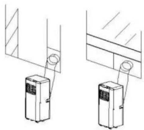
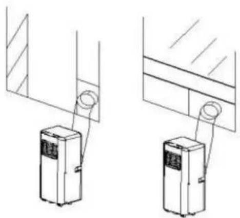
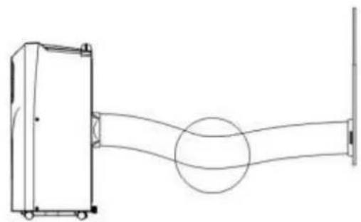
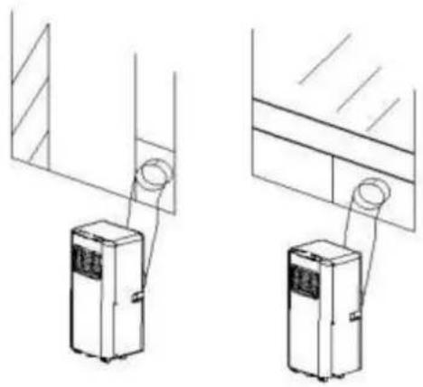
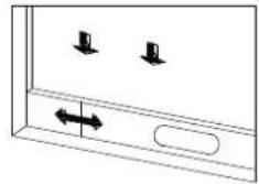
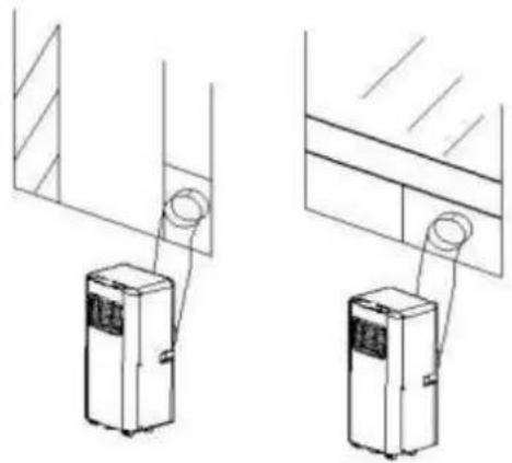
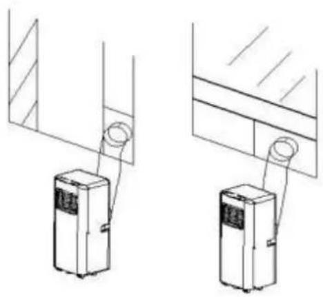
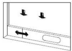
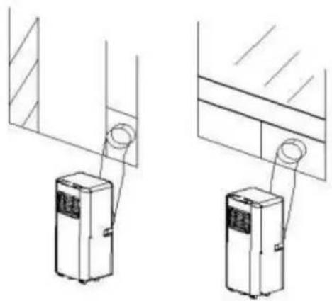
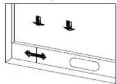
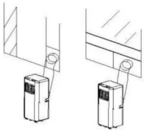
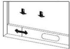
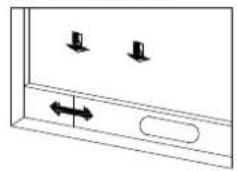
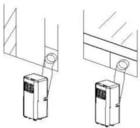
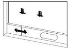
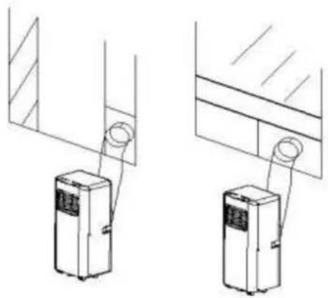
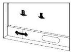
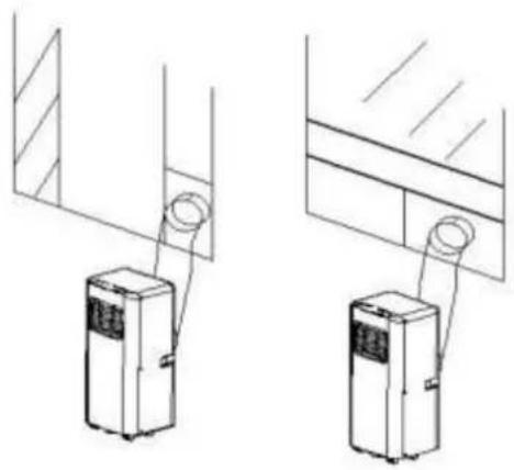
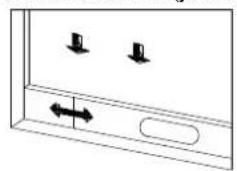
Half open the window and mount the window sealing board assembly onto the window, either vertically or horizontally (as shown in Figure 7 and 8).
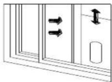
Fig. 7
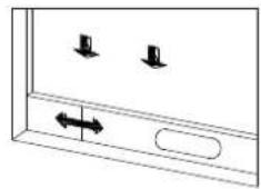
Fig. 8
Installation of the unit
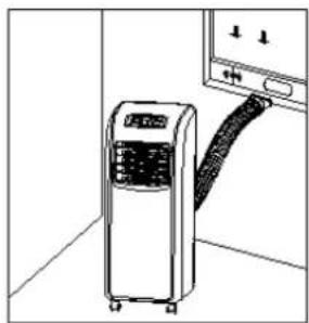
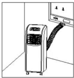
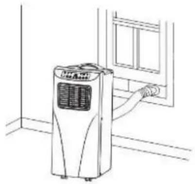
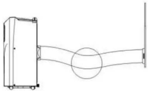
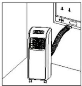
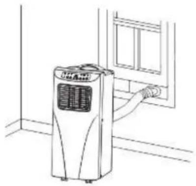
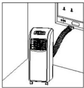
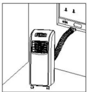
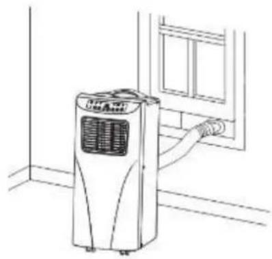
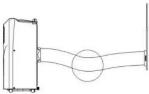
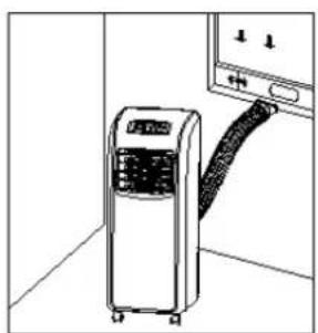
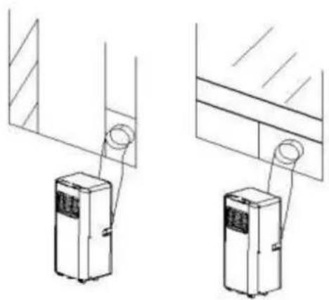
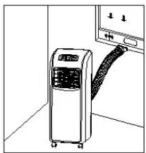
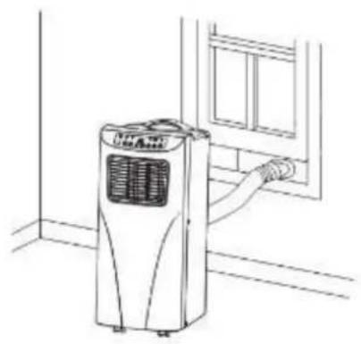
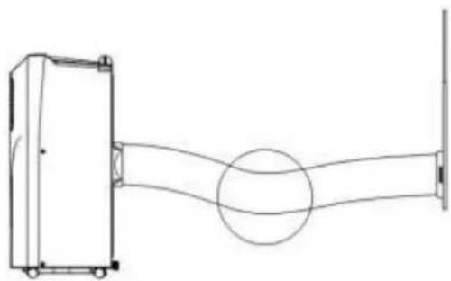
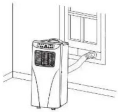
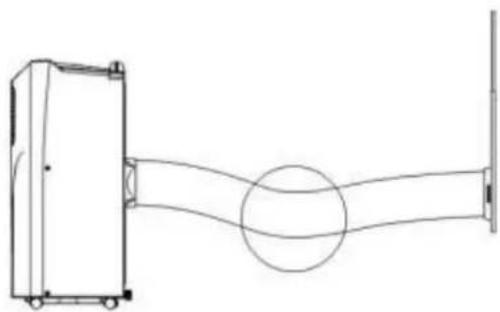
Move the unit with the heat exhaust hose assembly installed before the window and keep the unit at least 50cm away from the walls or other objects. (As shown in Figure 9).
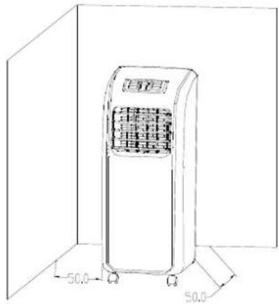
Fig. 9
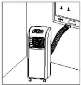
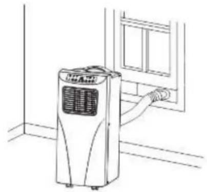
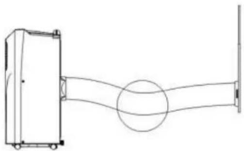
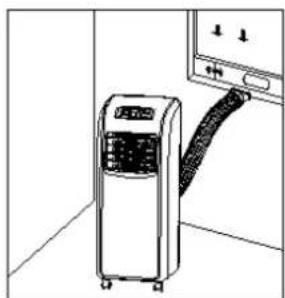
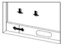
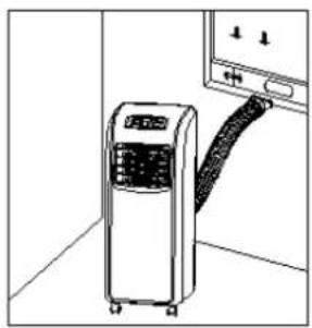
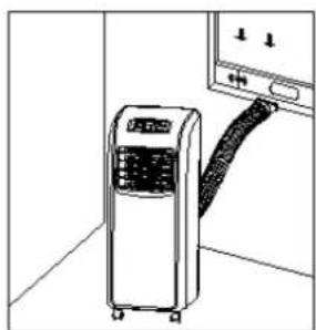
Snap the flat end of the heat exhaust hose short connector into the elliptical hole of the window sealing board assembly (as shown in Figure 10 and 11).
Note: 1. The flat end of the heat exhaust hose short connector must be snapped into place.
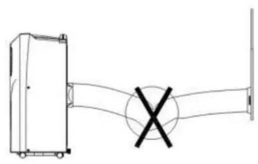
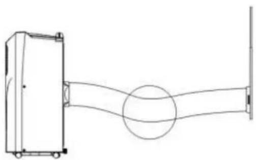
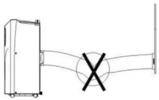
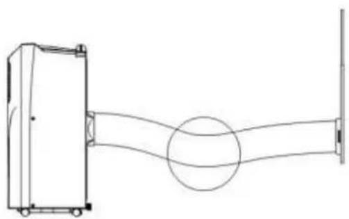
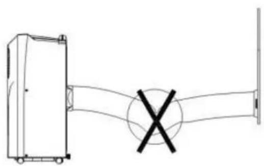
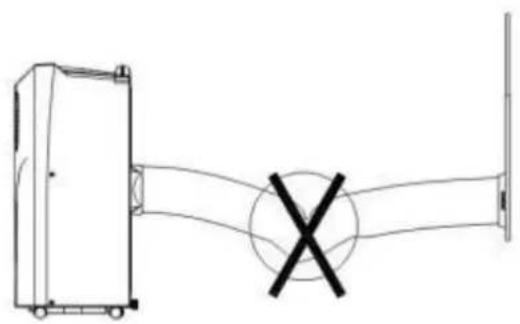
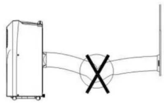
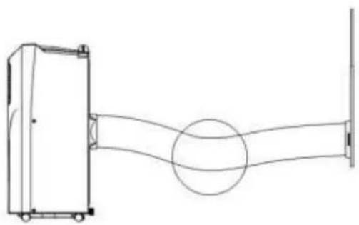
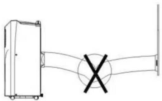
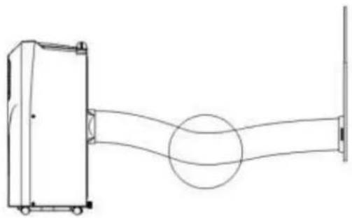
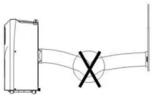
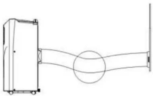
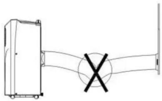
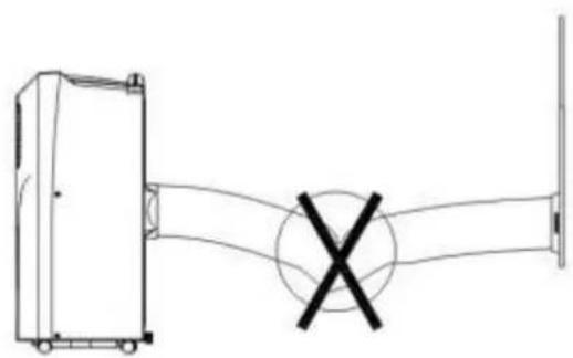
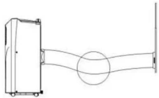
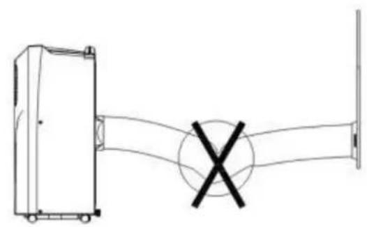
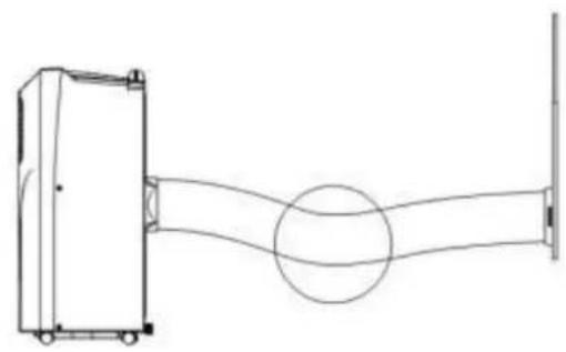
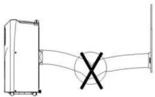
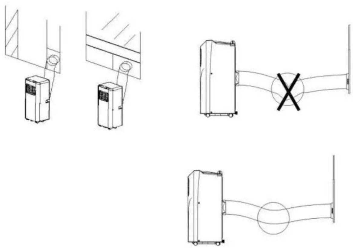
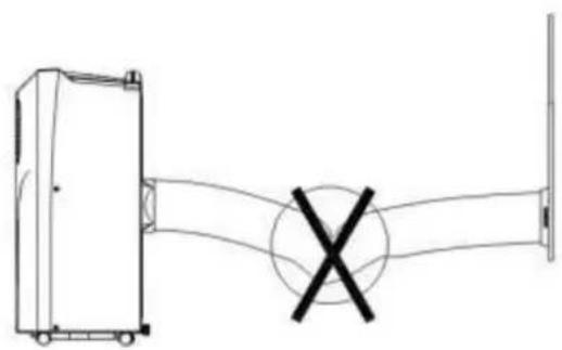
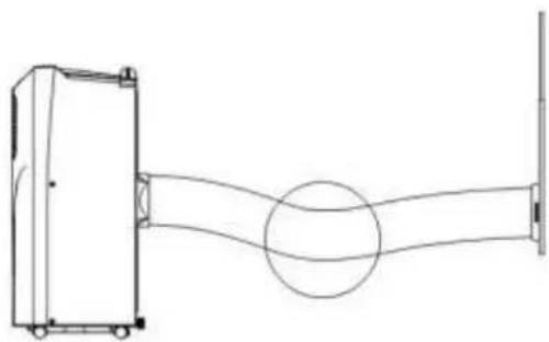
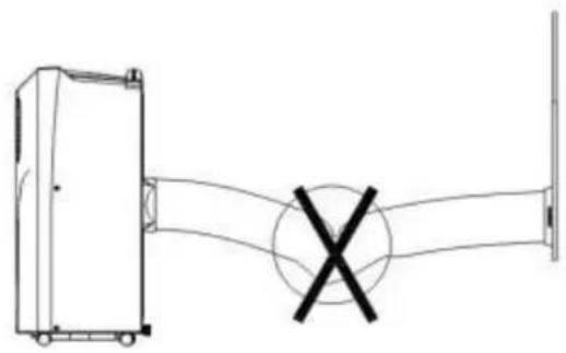
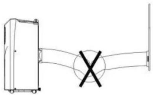
- The heat exhaust hose may not be bent and shall be free from significant (greater than 45° ) flexure, and the heat exhaust hose shall be ventilated properly.
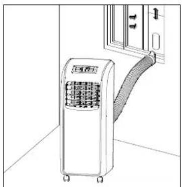
Fig. 10
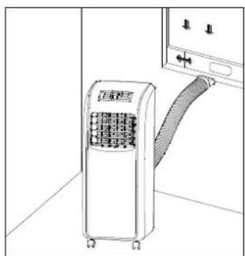
Fig. 11
Important notes:
- The exhaust hose is 280mm-1500mm long and this length is determined based on the specification of the air-conditioner (s). Do not use prolonged hose or replace with other different hoses as this may affect the functions of the air-conditioner. The exhaust must be smooth and the air-conditioner may overheat if the exhaust is obstructed.
- Make sure that the outlet is not blocked to prevent damage to the unit.
• The exhaust hose should not be bent.
Control panel
![graph TD A["11"] --> B["TIMER"] C["6"] --> D["POWER"] E["7"] --> D F["14"] --> G["MODE"] H["3"] --> I["FAN"] J["12"] --> K["1"] L["13"] --> M["2"] N["10"] --> O["4"] P["15"] --> Q["9"] R["11"] --> S["5"] T["6"] --> U["7"] V["14"] --> W["8"] X["15"] --> Y["15"]](/content/2026/02/397001/images/b43aea0585d7029bec0132ef5082b2360e63acbc6bf35c1c5aa1ed07ff7c7691.jpg)
-
On/Off Button
-
High/Low indicator
-
Mode Button
-
Full water indicator
-
Up/Down Button
-
Cooling mode indicator
-
Fan Button
-
Dehumidify mode indicator
-
Timer Button
-
Fan mode indicator
-
Display
-
Sleep mode indicator
-
Celsius/Fahrenheit degree indicator
-
Remote control sensor location
-
Timer indicator
-
Once you plug in the unit, you will hear the start sound; the display shows the ambient temperature. The unit is in the standby mode now.
-
ON/OFF button: press this button to start the unit or shut down the unit. Once you plug in the unit for the first time, it starts in the cooling mode, with high fan speed and temperature of 24° C ( 75° F).
-
MODE Button: Press this button to switch between cooling, fan and dehumidifying modes; the corresponding mode indicator will illuminate.
- Cooling mode: Press MODE button or COOL (remote control) to choose this mode. In this mode, press Up/Down button to set suitable temperature. The temperature range is 17\~30°C (62\~86°F). One press makes the temperature rise or fall on 1°C/1°F.
- Press Fan Button or High Low to choose suitable fan speed.
- Press the up button and down button simultaneously to switch between the Fahrenheit degree and Celsius degree. When the Celsius degree is displayed, the Celsius degree indicator illuminates.
- Press Timer button and Down button together or Sleep to choose Sleep mode. Under this mode, after the unit operates for 2 hours, the setting temperature raises on 1°C (1°F) automatically. After operating for another 2 hours, the setting temperature raises on 1°C (1°F) again. After that, the setting temperature won't change. This sleep mode is recommended to you for the night to give you good and sufficient sleep.
- In the dehumidifying mode, if the ambient temperature ≥ 17°C , the compressor will start. Then, the unit is controlled in the following manner: when the ambient temperature ≤ 15°C , the compressor shuts down. When the ambient temperature rises to be ≥ 17°C , the compressor starts again. The start/stop of the compressor meets the requirement for 3-minute protection time. The fan is forced to
switch to lower level.
- In the fan mode, only the fan motor works. The display shows only the ambient temperature. The setting temperature cannot be changed. This unit can blow the air to various angles.
-
FAN button: the fan may operate in the following manners:
-
In the cooling mode (except the sleep mode) and fan mode: high→low→high→ and so on.
-
Switching between the cooling, fan and drying modes: maintain the fan speed of the previous mode.
-
TIMER button:
-
After starting the unit, press the Timer button to enter timed shutdown. After shutdown the unit, press this button to enter timed start. In the meanwhile, the timer indicator will illuminate.
- Press the Timer button to enter the timing function (timed start/timed shutdown). Adjust the up or down button to set the timing time. The time will cycle in the order of 1-2-3-.....24-0-1 hours or 24-23-22-.....1-0-24 hours. The adjustment time of the timing function is relative time.
- After the time is set, once the timed start time is reached, the unit will start. In the meanwhile, the timer indicator will extinguish and the ambient temperature will be showed on the display.
- On/Off operations caused by the button or remote control will clear all timing settings.
- Once the timing is set, if the timer button is pressed once, it is possible to query the remaining start/shutdown time. If the timer button is pressed twice continuously within 5s, it is possible to cancel timing.
Remote control
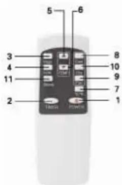
The operation instructions of the buttons of this simple remote control are as follows:
- Power button: press this button to turn on/off the unit;
-
Timer button: upon shutdown, press this button to set timed start; upon start, press this button to set timed shutdown.
-
High button: press this button to allow the unit to operate in the high fan speed state (except in the dry and sleep modes);
-
Low button: press this button to allow this unit to operate in the low fan speed state;
-
Up button: press this button to increase the temperature and timing value;
-
Down button: press this button to decrease the temperature and timing value;
-
°C — F button: press this button to switch between the Celsius degree and Fahrenheit degree;
-
Cool button: press this button to set this unit to operate in the cooling mode;
-
Fan button: press this button to set this unit to operate in the air supply mode;
-
Dehumidifying button: press this button to set this unit to operate in the dry mode;
-
Sleep mode: press this button to set this unit to operate in the sleep mode.
Protection functions:
- Anti-freeze protection function:
In the cooling mode, when the compressors operates continuously for more than 10 minutes, if the pipe temperature Tp is less than or equal to 2°C continuously for 20 seconds, the compressor and water spraying motor turn off, other loads operate and the display shows E4, the unit initiates the anti-frost protection function and the buttons are inactive (except the OFF button). Once the pipe temperature rises to exceed or equal 8°C, the protection is relieved, the original status is restored and the unit meets the requirements for 3-minute delay protection of the compressor.
- Full water protection function:
When the water in the water tray exceeds the alarm level, the unit will alarm automatically and the full water indicator illuminates. In this case, you need to drain the condensate in the unit; otherwise, the unit will shut down automatically after the buzzer gives off 5 beeps. (For more information about the
drain method, refer to the "Drain"). If the unit is not shut down manually, the unit will be restored to the previous operating status automatically once the water is fully drained. Or the power may be turned on again to start the unit.
3. Delay protection function of the compressor:
This unit offers restart protection for the compressor. Except that the compressor may start immediately when the unit is energized for the first time, there is 3-minute delay start protection after the compressor is shut down.
Emptying of the water tank
- The unit has an automatic water evaporation system. Condensed water will be used to cool the condenser. Thus the cooling performance will be increased and the energy will be saved.
- As soon as the water tank is full, the "FL" blinks on the display, the standby mode automatically turns on, it will sound the warning alarm and all the buttons will be locked until the tank is emptied.
- To empty of the water tank you need to remove the rubber stopper on the bottom of the unit and let the water leak into a container.
- Turn off the power and unplug the power cord. Once you reboot the device, it will work normally.
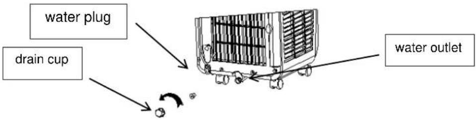
Cleaning
Before starting cleaning or maintenance, turn the power off by pressing the POWER button, wait a few minutes and then unplug the power cord from the outlet.
Surface cleaning
- Unplug the unit.
- Clean the unit using a damp cloth, and then wipe it using a dry cloth. Do not use chemical solvents (such as gasoline, alcohol).
- Do not use the water for the cleaning of the unit
Air filter cleaning
Clean the air filter regularly (every 2 weeks). If the air filter is clogged with dust, the efficiency of the device could be reduced.
Pull out the air filter frame and condenser filter frame in the direction as shown in figure 15. Now you can then remove the air filter and condenser filter as shown on figure 16.
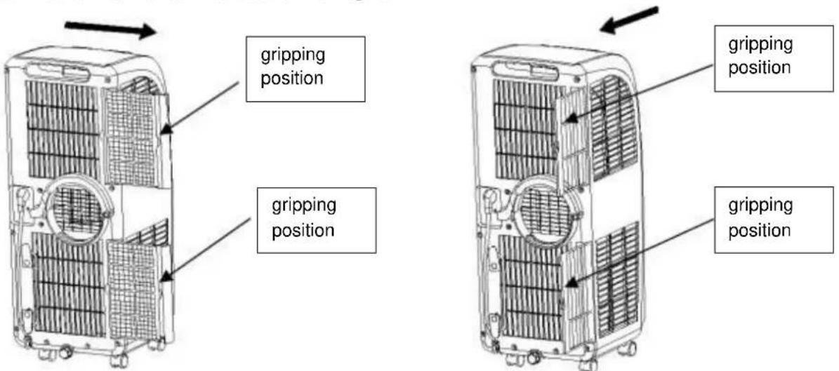
Wash the air filter by submersion into warm water (about 40° C) with neutral detergent, rinse it under running water and dry it with a soft cloth.
Note: Please make sure not to damage frames during the cleaning,
Storage
- Pull the power plug and empty the water tank. Then set the device into the operating mode. Press the fan button and hold it for a. 5 seconds until the device switches to low fan speed. Let the unit run in this mode for half a day until the inner construction has dried. Thus, it will not become mouldy.
- Turn off the unit and unplug the power cord.
- Coil the cord and attach it to the holder.
- Disconnect the exhaust tubing from the device and keep it safe.
- Put the unit into a box and bring it to a dry place.
- Remove the batteries from the remote control and keep them safe as well.
Troubleshooting
Don't repair or disassemble the unit by yourself, unsuitable repair may make the quality-protected card in vain, and even cause damage to the user or his/her possession.
| Problems | Cause | Solution |
| The unit does not work. | Power cord is not plugged. | Insert the plug into the socket and turn on the unit. |
| Water full indicator lamp blinks. | Empty the water tank. | |
| Ambient temperature too low. | Please operate the unit only by the ambient temperature of 10-35°C | |
| The room temperature is lower than the set temperature in the cooling mode. | Please change the set temperature. | |
| Bad cooling or heating effects | There is direct sunlight | Draw the curtain on. |
| The doors and windows are open, the room is crowded or there are other heat sources in the cooling mode. | Close the door and window and add new air-conditioners. | |
| Filter mesh is dirty. | Clean or replace the filter mesh | |
| Air inlet or air outlet are clogged. | Remove the obstruction. | |
| Large noise | Air-conditioner not put on a flat surface | Put the air-conditioner in a flat and firm place (may reduce noise) |
| The compressor does not work | Initiation of overheat protection. | Wait 3 minutes until the temperature decreases and then turn on the unit |
| The remote control does not work | Too long a distance | Bring the remote control close to the air-conditioner and ensure that the remote control points toward the receiving head of the remote control. |
| The remote control does not point toward the receiving head of the remote control | ||
| The batteries have no electricity | Replace the batteries | |
| Display E1 | Pipe temperature sensor failure | Check the pipe temperature sensor and related circuits |
| Display E2 | Room temperature sensor failure | Check the room temperature sensor and related circuits |
| Display E4 | Anti-freeze protection | Restore the functions automatically once defrozen. |
| Full water indicator illuminates | The water in the baseplate of the unit reaches the full water level | Drain the water in the baseplate. |
Spare parts and accessories supply (fast convenient supply)
You can obtain spare parts and accessories for your SUMMIT unit from your local dealer. And at our website
www.suntec-wellness.de
you will find further information on individual accessory products as well as information on obtaining our spare parts quickly and conveniently. You will also find other information (e.g. FAQ, lists of spare parts, document download, etc) about your SUMMIT unit.
| NameEAN | Description | Drawing |
| Air-Block Klima-Sail4250058312099 | Sail which can be used for all types of windows and doors. As for an external fly screen, it is fixed with Velcro and operated via a zip. The window or door can be closed at any time. |  |
| Air-Extension-Kit4250058312105 | A World First with which you can air-condition almost every corner of your house, and it doesn't matter where the local air conditioner is located. You can extend the extract air hose by 5 meters via a special propeller. For SUMMIT this also applies for the air supply and extraction. |  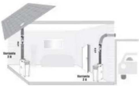 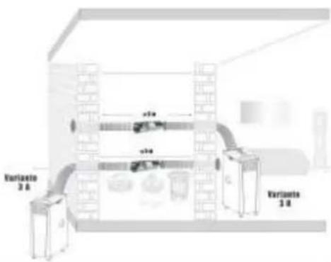 |
| SUMMIT Wall-Kit4250058312471 | Clean closing of a wall or wall boring from inside and outside with connection element for the air hose. | 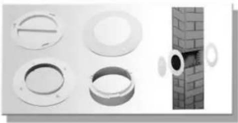 |
| Window-Kit4250058312016 | Sliding seal of window and connection adapter for air hose, especially for sliding windows. |  |
In the case of complaints
• Would you like to complain about the device, you can do it within 24 months from the date of purchase (receipt).
- A free replacement or repair will be excluded from the prior improper product manipulation.
- Defects on parts and consumables, as well as cleaning, maintenance or replacement of said parts are therefore chargeable.
- If you want to make a claim, so please bring the whole unit in its original packaging and with proof of purchase to your dealer. For a timely and convenient service register, visit our website also www.suntec-wellness.de and learn more.
- No proof of purchase will generally not free repair or replacement.
- In the event that the complaint case is analogous to our terms of service, all defects of the device or its accessories due to material or manufacturing faults by repair or, at our option, by replacement of the device.
- The damage of accessories does not automatically lead to a free replacement of the entire unit. In these cases, please contact your dealer. Glass breakage, or breakage of plastic parts is always a charge.
- The dealer or repair after the warranty service can carry out repairs with costs.
EC-Declaration of Conformity
The unit complies with the essential health and safety requirements of the European Union. The EC declaration of conformity is the basis for the CE marking of this unit.
With the publication of this manual, all previous are not valid. SUNTEC, SUNTEC Wellness, KLIAMTRONIC and the Sun logo are registered trademarks. © 2016/01 SUNTEC WELLNESS GMBH
ERP regulation
This high-quality single-channel portable air conditioning unit is in accordance with the rules and regulations of the European Union, in particular the new ERP Regulation 626/2011 to a "local air conditioner."
Refrigerant
(CE) N 842/2006: This local air conditioner contains the refrigerant R410A. The amount of refrigerant is less than 1kg, and is in a closed cooling circuit. The coolant does have zero ozone depletion potential, but is a so-called greenhouse gases under the Kyoto Protocol and may thus contribute to global warming, if it is released to the atmosphere. Therefore only trained technicians with refrigerant certificate make a filling or emptying. Suntec your local air conditioner does not have to use if used properly and undamaged coolant circuit can be refilled with refrigerant.
GWP: R410A (R32/125: 50:50): 2087,5
Note concerning protection of environment
This product must not be disposed of via normal household waste after its service life, but must be taken to a collection station for the recycling of electrical and electronic devices. The symbol on the product, the operating instructions or the packaging indicate such disposal procedures. The materials are recyclable in accordance with their respective symbols. By means of re-use, material recycling or any other form of recycling old appliances you are making an important contribution to the protection of our environment. Please ask your local council where your nearest disposal station is located.
© 2016 KLIMATRONIC® SUMMIT plus
SUNTEC WELLNESS GMBH / HOLZSTRASSE 2 / 40221 DÜSSELDORF / GERMANY
Dib. 1
Dib.2
Dib. 3
Dib. 4
Muy importante!
![graph TD A["Device 1"] --> B["Processing Unit"] C["23"] --> B D["24"] --> B](/content/2026/02/397001/images/7d65e35df5aaa37eaa99601906cc8275c52e8eaef9b9272289b75dde7988f356.jpg)
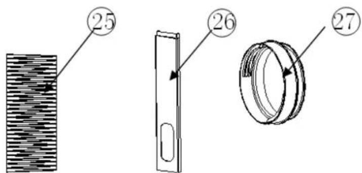
Figura 1
Figura 7
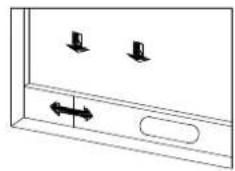
Figura 8
EC-Declaration of Conformity
The unit complies with the essential health and safety requirements of the European Union. The EC declaration of conformity is the basis for the CE marking of this unit.
With the publication of this manual, all previous are not valid. SUNTEC, SUNTEC Wellness, KLIAMTRONIC and the Sun logo are registered trademarks. © 2016/01 SUNTEC WELLNESS GMBH
ERP Regulation
This high-quality single-channel portable air conditioning unit is in accordance with the rules and regulations of the European Union, in particular the new ERP Regulation 626/2011 to a "local air conditioner."
Refrigerant
(CE) N 842/2006: This air conditioner contains the refrigerant R410A. The amount of refrigerant is less than 1kg, and is in a closed cooling circuit. The coolant does have zero ozone depletion potential, but is a so-called greenhouse gases under the Kyoto Protocol and may thus contribute to global warming, if it is released to the atmosphere. Therefore only trained technicians with refrigerant certificate make a filling or emptying. Suntec your air conditioner does not have to use if used properly and undamaged coolant circuit can be refilled with refrigerant.
GWP: R410A (R32/125: 50:50): 2087,5
© 2016 KLIMATRONIC® SUMMIT plus
SUNTEC WELLNESS GMBH / HOLZSTRASSE 2 / 40 221 DÜSSELDORF / DEUTSCHLAND
Fig. 1 Fig.2
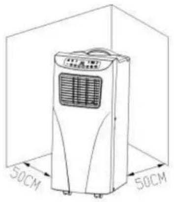
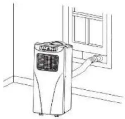
Fig. 3 Fig. 4
TRÈS IMPORTANT!
![graph TD A["Device 1"] --> B["Process Unit 1"] B --> C["Process Unit 2"] C --> D["Output Step 24"] style A fill:#f9f,stroke:#333 style D fill:#bbf,stroke:#333](/content/2026/02/397001/images/e6172c668f049984c7cbc5f883eaa6a7b89f315ea712710a32b7cf5d403f40ec.jpg)

Fig. 1
Fig. 1 Fig. 2
Fig. 7 Fig. 8
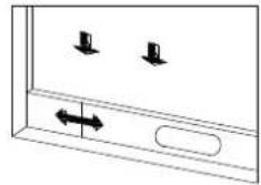
Fig. 9
© 2016 KLIMATRONIC® SUMMIT plus
SUNTEC WELLNESS GMBH / HOLZSTRASSE 2 / 40 221 DÜSSELDORF / DEUTSCHLAND

![graph TD A["Device 1"] --> B["Processing Unit"] C["Step 23"] --> B D["Step 24"] --> B](/content/2026/02/397001/images/8c437e82b0d9bbf7755ad66be38ed5432c5f521391aaea529255c096f1a18bba.jpg)
Afb. 1 Afb. 2
Afb. 7
Afb. 8
Positioneren van de airconditioning
Afb. 9
© 2016 KLIMATRONIC® SUMMIT plus
SUNTEC WELLNESS GMBH / HOLZSTRASSE 2 / 40 221 DÜSSELDORF / DUITSLAND
MOLTO IMPORTANTE!
![graph TD A["Device"] --> B["Processing Unit"] B --> C["Step 23: Input Device"] B --> D["Step 24: Output Unit"]](/content/2026/02/397001/images/2ae5c7595a74d18a7cf8923819f16a709d0a90595ad758b2d825c532bc4427b4.jpg)
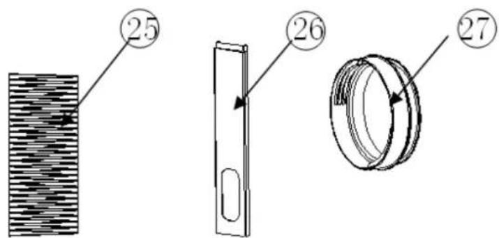
Fig. 1
Fig. 1 Fig. 2
Fig. 7 Fig. 8
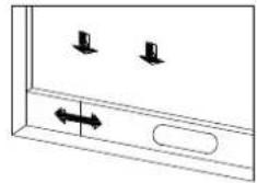
Fig. 9
Fig. 10
© 2016 KLIMATRONIC® SUMMIT plus
SUNTEC WELLNESS GMBH / HOLZSTRASSE 2 / 40 221 DÜSSELDORF / DEUTSCHLAND
Slika 1 Slika 2
Slika 3 Slika 4
VAŽNO UPOZORENJE!
Nemojte instalirati ili koristiti svoj mobilni klima-uredaj prije no što pažljivo pročitate ove upute za rukovanje. Upute sačuvajte zbog eventualnog jamstva, ali i kao izvor informacija o proizvodu.
Upozorenje!
![graph TD A["Device 1"] --> B["Processing Unit"] C["Device 2"] --> B D["Device 3"] --> B](/content/2026/02/397001/images/f3d07d8ae5125ac02c95e1a0bfb96c607aa00d18ff8d84fe2161f9962c478b71.jpg)
slika 1
Upozorenje: Prije no što počnete koristiti uređaj, morate ga ostaviti da stoji uspravno najmanje 24 sata. Uređaj možete bez problema premještati iz prostorije u prostoriju, ali pridržavajte se pri tome sljedećih uputa:
slika 1 slika 2
slika 7 slika 8
Smještanja uređaja za klimatizaciju
Uređaj mora stajati na podu udaljen 50 cm od ostalih predmeta, jer oni mogu jako utjecati na učinkovitost rada samog uređaja. Osim toga preporučujemo da instalirate cijev za otpadni zrak prije no što uređaj za klimatizaciju stavite u željeni položaj (slika 9).
slika 9
© 2016 KLIMATRONIC® SUMMIT plus
SUNTEC WELLNESS GMBH / HOLZSTRASSE 2 / 40 221 DÜSSELDORF / DEUTSCHLAND
Sl. 1 Sl.2

Sl. 3 Sl. 4
VAŽNO UPOZORENJE!
Nemojte instalirati ili koristiti svoj mobilni klima-uređaj prije nego što pažljivo pročitate ovo uputstvo za rukovanje. Uputstvo sačuvajte zbog eventualne garancije, ali i kao izvor informacija o proizvodu.
Upozorenje!

![graph TD A["Device 1"] --> B["Processing Unit"] C["Device 2"] --> D["Processing Unit"] B --> E["Output Unit"] D --> E](/content/2026/02/397001/images/173376c8fd00c6dc289eca4b71299fdc3390d053995ad6269e57149d1e781945.jpg)
slika 1
Upozorenje: Prije no što počnete da upotrebljavate aparat, morate ga ostaviti da stoji uspravno najmanje 24 sata.
Aparat možete bez problema premještati iz prostorije u prostoriju, ali pridržavajte se pri tome sljedećih uputstava:
slika 1 slika 2
slika 7 slika 8
Postavljanje aparata za klimatizaciju
Aparat mora stajati na podu udaljen 50 cm od ostalih predmeta, jer oni mogu jako utjecati na učinkovitost rada samog aparata. Osim toga preporučujemo da instalirate cijev za otpadni zrak prije no što aparat za klimatizaciju stavite u željeni položaj (slika 9).
slika 9
© 2016 KLIMATRONIC® SUMMIT plus
SUNTEC WELLNESS GMBH / HOLZSTRASSE 2 / 40 221 DÜSSELDORF / DEUTSCHLAND
Slika 1 Slika 2
Slika 3 Slika 4
ZELO POMEMBNO!
![graph TD A["Device 1"] --> B["Processing Unit"] C["Device 2"] --> D["Processing Unit"] style A fill:#f9f,stroke:#333 style C fill:#bbf,stroke:#333 style B fill:#dfd,stroke:#333 style D fill:#dfd,stroke:#333](/content/2026/02/397001/images/3d7a7890c5603056e9b319ae93cbe12015a984bbafaa97949e9d427409a6b113.jpg)
Pozor: Naprava mora pred uporabo najmanj 24 ur stati pokonci.
slika 1 slika 2
- V vsako roko primite po en del in vezni del ene polovice vstavite v vezni del druge polovice. Nato jih previdno stisnite, da se zatakneta (slika 1A).
- Raztegnite majhen del enega konca cevi za odvod zraka. Sedaj lahko ta konec cevi privijete na nastavek v nasprotni smeri urinega kazalca (slika 2A).
- Tudi drugi konec odvodne cevi rahlo raztegnite. Nanj v nasprotni smeri urinega kazalca privijete zožitev cevi (slika 1).
- Na sliki 2 je prikazana končna cev za odvod zraka z zožitvijo in nastavkom.
slika 7
slika 8
Pozicioniranje klimatske naprave
slika 9
Cev za odvod zraka na nastavek za okno montirate z zožitvijo cevi (slika 9 in slika 10).
© 2016 KLIMATRONIC® SUMMIT plus
SUNTEC WELLNESS GMBH / HOLZSTRASSE 2 / 40 221 DÜSSELDORF / DEUTSCHLAND
Obr. 1
Obr. 2
Obr. 3
Obr. 4
VEL'MI DÔLEŽITÉ!
![graph TD A["Device 1"] --> B["Processing Unit"] C["Device 2"] --> D["Processing Unit"] style A fill:#f9f,stroke:#333 style C fill:#bbf,stroke:#333 style B fill:#dfd,stroke:#333 style D fill:#dfd,stroke:#333](/content/2026/02/397001/images/352e87c3004fc4ce28dc7ecf5c1549dedd3d10f0a098214d664ddac754fdf182.jpg)
Obr. 1
Obr. 1 Obr. 2
Obr. 7
Obr. 8
Obr. 9
© 2016 KLIMATRONIC® SUMMIT plus
SUNTEC WELLNESS GMBH / HOLZSTRASSE 2 / 40 221 DÜSSELDORF / DEUTSCHLAND
VELMI DÙLEŽITÉ!
![graph TD A["Device 1"] --> B["Processing Unit"] C["Device 2"] --> D["Processing Unit"] style A fill:#f9f,stroke:#333 style C fill:#bbf,stroke:#333 style B fill:#dfd,stroke:#333 style D fill:#dfd,stroke:#333](/content/2026/02/397001/images/8b1df90fd28834744fd8d8c2877e0ef0d0666b056c0fb24335b51f63c1cbd978.jpg)
Obr. 1 Obr. 2
Obr. 7
Obr. 8
Obr. 9
Obr. 11
© 2016 KLIMATRONIC® SUMMIT plus
SUNTEC WELLNESS GMBH / HOLZSTRASSE 2 / 40 221 DÜSSELDORF / DEUTSCHLAND
Rysunek 1 Rysunek 2
Rysunek 3 Rysunek 4
BARDZO WAŻNE!
![graph TD A["Device"] --> B["Processing Unit"] B --> C["Step 23: Input Device"] B --> D["Step 24: Output Unit"]](/content/2026/02/397001/images/cfba03c4ab9ba6321c4f6a927927f1ec2b422b4da8d625c2293e760e2135dd42.jpg)
Rys. 1
Rys. 1 Rys. 2
Rys. 7
Rys. 8
Rys. 9
Rys. 10
© 2016 KLIMATRONIC® SUMMIT plus
SUNTEC WELLNESS GMBH / HOLZSTRASSE 2 / 40 221 DÜSSELDORF / NIEMCY
Figura 1 Figura 2
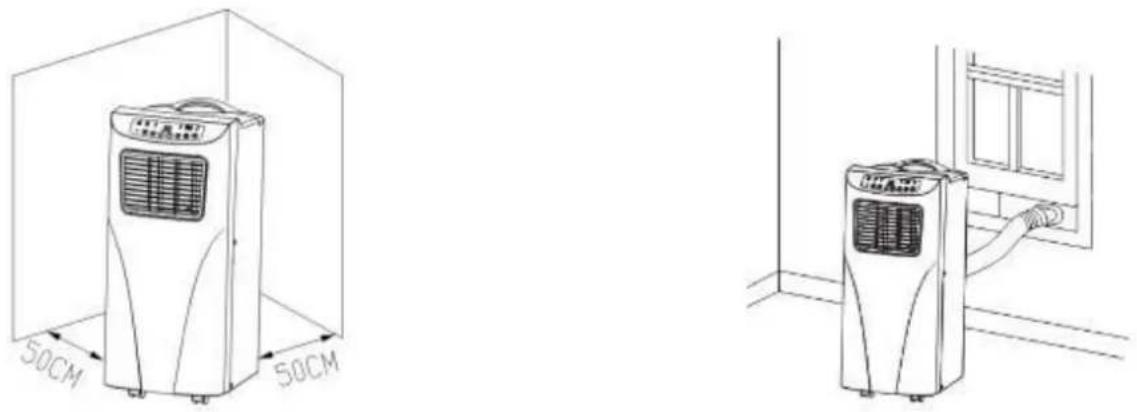
Figura 3 Figura 4
![graph TD A["Device"] --> B["Step 2"] B --> C["Step 3"] C --> D["Step 4"]](/content/2026/02/397001/images/0eab993fc3d1c3838ae0b00a5e3703e808a3b0bdd2ad1811b76bece0c0417192.jpg)
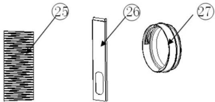
Fig. 1
Fig. 1A
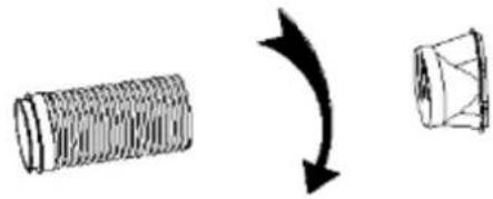
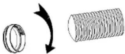
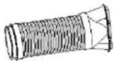
Fig. 1
Fig. 2
Fig. 7
Fig. 8
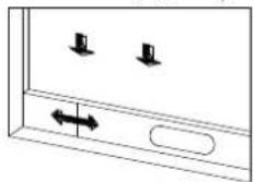
Fig. 9
Fig. 10
Fig. 11
© 2016 KLIMATRONIC® SUMMIT plus
SUNTEC WELLNESS GMBH / HOLZSTRASSE 2 / 40 221 DÜSSELDORF / DEUTSCHLAND
Bild 1
Bild 2
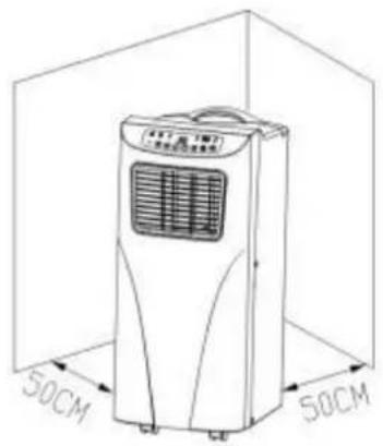
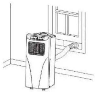
Bild 3
Bild 4
MYCKET VIKTIGT!
![graph TD A["Device 1"] --> B["Processing Unit"] C["Step 23"] --> B D["Step 24"] --> B](/content/2026/02/397001/images/c72aa257e31df182795b23af896587068cf1111f48b0128fde12e070603dbe38.jpg)
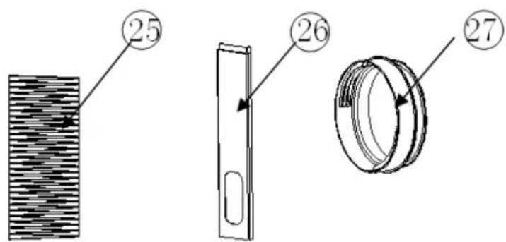
Bild. 1
Bild 7
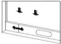
Bild. 8
Bild 9
In the case of complaints
• Would you like to complain about the device, you can do it within 24 months from the date of purchase (receipt).
- A free replacement or repair will be excluded from the prior improper product manipulation.
- Defects on parts and consumables, as well as cleaning, maintenance or replacement of said parts are therefore chargeable.
- If you want to make a claim, so please bring the whole unit in its original packaging and with proof of purchase to your dealer. For a timely and convenient service register, visit our website also www.suntec-wellness.de and learn more.
- No proof of purchase will generally not free repair or replacement.
- In the event that the complaint case is analogous to our terms of service, all defects of the device or its accessories due to material or manufacturing faults by repair or, at our option, by replacement of the device.
- The damage of accessories does not automatically lead to a free replacement of the entire unit. In these cases, please contact your dealer. Glass breakage, or breakage of plastic parts is always a charge.
- The dealer or repair after the warranty service can carry out repairs with costs.
EC-Declaration of Conformity
The unit complies with the essential health and safety requirements of the European Union. The EC declaration of conformity is the basis for the CE marking of this unit.
With the publication of this manual, all previous are not valid. SUNTEC, SUNTEC Wellness, KLIAMTRONIC and the Sun logo are registered trademarks. © 2016/01 SUNTEC WELLNESS GMBH
ERP Regulation
This high-quality single-channel portable air conditioning unit is in accordance with the rules and regulations of the European Union, in particular the new ERP Regulation 626/2011 to a "local air conditioner."
Refrigerant
(CE) N 842/2006: This air conditioner contains the refrigerant R410A. The amount of refrigerant is less than 1kg, and is in a closed cooling circuit. The coolant does have zero ozone depletion potential, but is a so-called greenhouse gases under the Kyoto Protocol and may thus contribute to global warming, if it is released to the atmosphere. Therefore only trained technicians with refrigerant certificate make a filling or emptying. Suntec your air conditioner does not have to use if used properly and undamaged coolant circuit can be refilled with refrigerant.
GWP: R410A (R32/125: 50:50): 2087,5
Miljöskddsanvisningar
© 2016 KLIMATRONIC® SUMMIT plus
SUNTEC WELLNESS GMBH / HOLZSTRASSE 2 / 40 221 DÜSSELDORF / TYSKLAND
- ábra
- ábra
- ábra
- ábra
NAGYON FONTOS!
![graph TD A["Device"] --> B["Diagram 1"] B --> C["Diagram 2"] C --> D["Diagram 3"]](/content/2026/02/397001/images/ce868eb664baa1dbda74337b22fea3761b8862ccebd3275af2f5708a815bfa01.jpg)
1. ábra 2. ábra
- ábra
- ábra
- ábra
- ábra

This high-quality single-channel portable air conditioning unit is in accordance with the rules and regulations of the European Union, in particular the new ERP Regulation 626/2011 to a "local air conditioner."
Hütöközeg
© 2016 KLIMATRONIC® SUMMIT plus
SUNTEC WELLNESS GMBH / HOLZSTRASSE 2 / 40 221 DÜSSELDORF / DEUTSCHLAND
Joonis 1
Joonis 2
Joonis 3
Joonis 4
^
VÄGA TÄHTIS!
![graph TD A["Device"] --> B["Processing Unit"] B --> C["Step 23: Input Device"] B --> D["Step 24: Output Unit"]](/content/2026/02/397001/images/93744a52e2116b796483ce977b4a89585ac96b0cff658a5fbfc59579955dcd3e.jpg)
Joonis 7
Joonis 8
Joonis 9
This high-quality single-channel portable air conditioning unit is in accordance with the rules and regulations of the European Union, in particular the new ERP Regulation 626/2011 to a "local air conditioner."
REFRIGERANT
(CE) N 842/2006: This air conditioner contains the refrigerant R410A. The amount of refrigerant is less than 1kg, and is in a closed cooling circuit. The coolant does have zero ozone depletion potential, but is a so-called greenhouse gases under the Kyoto Protocol and may thus contribute to global warming, if it is released to the atmosphere. Therefore only trained technicians with refrigerant certificate make a filling or emptying. Suntec your air conditioner does not have to use if used properly and undamaged coolant circuit can be refilled with refrigerant.
GWP: R410A (R32/125: 50:50): 2087,5
© 2016 KLIMATRONIC® SUMMIT plus
SUNTEC WELLNESS GMBH / HOLZSTRASSE 2 / 40 221 DÜSSELDORF / DEUTSCHLAND

- SEHR WICHTIG
- VERY IMPORTANT
- SAFETY INSTRUCTION
- COMPONENTS
- INSTALLATION
- INSTALLATION OF THE C-SHAPED BUCKLE OF THE HEAT EXHAUST HOSE AND UNIT
- INSTALLATION OF THE HEAT EXHAUST HOSE ASSEMBLY AND UNIT (FIG. 5 AND FIG. 6)
- INSTALLATION OF THE WINDOW SEALING BOARD ASSEMBLY
- INSTALLATION OF THE UNIT
- IMPORTANT NOTES
- CONTROL PANEL
- REMOTE CONTROL
- PROTECTION FUNCTIONS
- DELAY PROTECTION FUNCTION OF THE COMPRESSOR
- EMPTYING OF THE WATER TANK
- CLEANING
- SURFACE CLEANING
- AIR FILTER CLEANING
- STORAGE
- TROUBLESHOOTING
- SPARE PARTS AND ACCESSORIES SUPPLY (FAST CONVENIENT SUPPLY)
- IN THE CASE OF COMPLAINTS
- EC-DECLARATION OF CONFORMITY
- ERP REGULATION
- REFRIGERANT
- NOTE CONCERNING PROTECTION OF ENVIRONMENT
- MUY IMPORTANTE
- TRÈS IMPORTANT
- POSITIONEREN VAN DE AIRCONDITIONING
- MOLTO IMPORTANTE
- VAŽNO UPOZORENJE
- UPOZORENJE
- SMJEŠTANJA UREĐAJA ZA KLIMATIZACIJU
- POSTAVLJANJE APARATA ZA KLIMATIZACIJU
- ZELO POMEMBNO
- POZICIONIRANJE KLIMATSKE NAPRAVE
- VEL'MI DÔLEŽITÉ
- VELMI DÙLEŽITÉ
- BARDZO WAŻNE
- MYCKET VIKTIGT
- MILJÖSKDDSANVISNINGAR
- NAGYON FONTOS
- ÁBRA 2. ÁBRA
- HÜTÖKÖZEG
- VÄGA TÄHTIS
Brand : SUNTEC
Model : Summit 27+
Category : Air Conditioning