RAS16SKVPND - Air-conditioner TOSHIBA - Free user manual and instructions
Find the device manual for free RAS16SKVPND TOSHIBA in PDF.
| Product type | Split air conditioner, reverse cycle (heat pump) |
| Brand | Toshiba |
| Model | RAS16SKVPND (indoor unit) / RAS16SAVPND (outdoor unit) |
| Power supply | 220–240 V ~ 50 Hz |
| Cooling capacity | 4.5 kW |
| Heating capacity | 5.5 kW |
| Indoor unit dimensions (W × H × D) | 790 × 250 × 208 mm |
| Outdoor unit dimensions (W × H × D) | 780 × 550 × 290 mm |
| Indoor unit weight | 9 kg |
| Outdoor unit weight | 38 kg |
| Cooling current | 0.15 A (indoor) / 6.18–5.65 A (outdoor) |
| Heating current | 0.15 A (indoor) / 6.83–6.25 A (outdoor) |
| Cooling power | 30 W (indoor) / 1,320 W (outdoor) |
| Heating power | 30 W (indoor) / 1,460 W (outdoor) |
| Operating modes | Auto (A), Cooling, Heating, Dehumidification, Fan, 8°C Mode, Hi POWER, Sleep |
| Special functions | Air purification (Plasma pur filter), Timer (ON/OFF, combined, daily), Memory (MEMO), Auto restart |
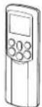
| Remote control | Infrared, with wall holder, AAA batteries (2) |
| Filters | Air filter (clean every 15 days), Plasma pur filter (clean every 6 months or after 1,000 hours of PURE mode) |
| Maintenance | Clean indoor and outdoor units, remote control, filters. Safety instructions for cleaning. |
| Safety | 3-minute protection, automatic stop in case of anomaly, professional installation required, mandatory grounding |
| Operating temperature range (cooling) | Indoor: 21–32 °C; Outdoor: -10–46 °C |
| Operating temperature range (heating) | Outdoor: -15–24 °C |
| Supplied accessories | Remote control, remote control holder, batteries (2 × AAA), Plasma pur filter (pre-installed) |
Frequently Asked Questions - RAS16SKVPND TOSHIBA
User questions about RAS16SKVPND TOSHIBA
0 question about this device. Answer the ones you know or ask your own.
Ask a new question about this device
Download the instructions for your Air-conditioner in PDF format for free! Find your manual RAS16SKVPND - TOSHIBA and take your electronic device back in hand. On this page are published all the documents necessary for the use of your device. RAS16SKVPND by TOSHIBA.
USER MANUAL RAS16SKVPND TOSHIBA
LUFTKONDITIONERING (SPLITTYP)
KLIMAANLEGG (DELT TYPE)
For general public use
natural_image
Line drawing of a wall-mounted air conditioner with a remote control unit emitting sound waves (no text or symbols)| Indoor Unit Outdoor UnitUnité intérieure Unité extérieureInnenraumgerät AußengerätInomhusenhet UtomhusenhetВнутренний блокSisäyksikköIndendørs enhedInnendørsenhet | Наружный блокUlkoyksikköUdendørs enhedUtendørsenhet |
| RAS-10SKVP-NDRAS-13SKVP-NDRAS-16SKVP-ND | RAS-10SAVP-NDRAS-13SAVP-NDRAS-16SAVP-ND |
Thank you for purchasing this TOSHIBA Air Conditioner. Please read this owner's manual carefully before using your Air Conditioner.
SAFETY PRECAUTIONS....1
NAMES OF PARTS....3
NAMES AND FUNCTIONS OF INDICATORS AND CONTROLS
ON INDOOR UNIT....3
REMOTE CONTROLLER AND ITS FUNCTIONS....4
NAMES AND FUNCTIONS OF INDICATORS ON REMOTE
CONTROLLER....5
PREPARATION AND CHECK BEFORE USE 5
USING THE REMOTE CONTROLLER 7
ADJUSTING AIR FLOW DIRECTION....16
HOW THE AIR CONDITIONER WORKS ....18
TEMPORARY OPERATION 19
CLEANING OPERATION.... 19
USUAL MAINTENANCE....20
TROUBLESHOOTING....25
SPECIFICATIONS 27
TROUBLESHOOTING (Remote Controller) 28
FRANÇAIS
ACCESSOIRES....1
MESURES DE SECURITE....1
NOM DES PIECES.... 3
MINUTERIE D'ARRET (OFF) 1, 3, 5, 9H....12
MODE MINUTERIE....13
MODE MEMOIRE/CONFORT 15
REGLAGE DU SENS DU FLUX D'AIR....16
FONCTION DE REDEMARRAGE AUTOMATIQUE....17
COMMENT LE CLIMATISEUR FONCTIONNE .... 18
FONCTIONNEMENT TEMPORAIRE 19
OPERATION DE NETTOYAGE....19
ENTRETIEN REGULIER ....20
ENTRETIEN SPECIAL....22
FONCTIONNEMENT ET PERFORMANCES DU
CLIMATISEUR 24
DEPISTAGE DES PANNES 25
CARACTERISTIQUES TECHNIQUES 27
MINNE/KOMFORT-DRIFT....15
ANDRING AV LUFTFLODETS RIKTNING.... 16
AUTOMATISK ÅTERSTART 17
SÄ HÄR FUNGERAR LUFTKONDITIONERINGEN 18
TILLFÄLLIG DRIFT 19
RENGÖRING....19
VANLIGT UNDERHÅLL....20
SPECIELLT UNDERHÄLL 22
LUFTKONDITIONERINGENS DRIFT OCH PRESTANDA...... 24
FELSÖKNING 25
SPECIFICATIONER....27
KAUKOSÄÄDIN JA SEN TOIMINNOT....4
KAUKOSÄÄTIMEN OSOITTIMIEN NIMET JA TOIMINNOT...... 5
KÄYTTÖÄ EDELTÄVÄ VALMISTELU JA TARKASTUS....5
KAUKOSÄÄTIMEN KÄYTTÖ 7
AUTOMAATTIKÄYTTÖ 8
AUTOMAATTIKÄYTTÖ (AUTOMAATTIVAIHTO) 8
JÄÄHDYTYS JA LÄMMITYS....9
KUIVAUS....9
8 °C:n TOIMINTA 10
ILMANPUHDISTUS....11
SUURTEHOTOIMINTA....12
1, 3, 5, 9 TUNNIN POIS-AJASTIN.... 12
AJASTIMEN KÄYTTÖ....13
MUISTI- JA OMAT ASETUKSET -TOIMINTA 15
ILMAVIRRAN SUUNNAN SÄÄTÄMINEN....16
AUTOMAATTINEN UUDELLEENKÄYNNISTYS.... 17
ILMASTOINTILAITTEEN TOIMINTA 18
VÄLIAIKAINEN KÄYTTÖ 19
PUHDISTUS 19
TAVANOMAINEN KUNNOSSAPITO 20
MUU KUNNOSSAPITO 22
ILMASTOINTILAITTEEN TOIMINTA JA SUORITUSKYKY....24
VIANMÄÄRITYS 25
TEKNISET TIEDOT 27
VIANMÄÄRITYS (kaukosäädin)....28
DANSK
TILBEH∅R....1
SIKKERHEDSFORSKRIFTER 1
DELENES NAVN....3
NAVNE OG FUNKTIONER PÅ DEN INDEND∅RS ENHEDS
INDIKATORER OG BETJENINGER.... 3
FJERNBETJENINGEN OG DENS FUNKTIONER.... 4
NAVNE OG FUNKTIONER PÅ FJERNBETJENINGENS
INDIKATORER....5
FORBEREDELSE OG KONTROL INDEN ANVENDELSE ...... 5
ANVENDELSE AF FJERNBETJENINGEN 7
AUTOMATISK DRIFT....8
AUTOMATISK DRIFT (AUTOMATISK OMSKIFTNING)...... 8
AFKÖLING/OPVARMNING 9
T∅RRING 9
8°C-FUNKTION 10
LUFTRENSNING....11
H∅J EFFEKT 12
1,3,5,9T STOPTIMER 12
TIMERFUNKTION....13
HUKOMMELSE/KOMFORT....15
JUSTERING AF LUFTSTRÖMMENS RETNING....16
AUTOMATISK GENSTART 17
HVORDAN AIRCONDITIONANLÆGGET FUNGERER 18
MIDLERTIDIG BETJENING....19
RENG∅RINGSFUNKTION 19
ALMINDELIG VEDLIGEHOLDELSE....20
SÆRLIG VEDLIGEHOLDELSE 22
AIRCONDITIONANLÆGGETS DRIFT OG YDEEVNE ...... 24
FEJLFINDING 25
SPECIFICATIONER....27
FEJLFINDING (fjernbetjening) 28
NORSK
TILBEH∅R....1
SIKKERHETSANVISNINGER 1
NAVN PÅ DELER....3
NAVN PÅ INDIKATORER OG KONTROLLER PÅ
INNEND∅RSENHETEN, OG DERES FUNKSJONER.... 3
FJERNKONTROLLEN OG DENS FUNKSJONER.... 4
NAVN PÅ INDIKATORENE PÅ FJERNKONTROLLEN, OG
DERES FUNKSJONER 5
KLARGJ∅RING OG KONTROLL F∅R BRUK 5
BRUKE FJERNKONTROLLEN 7
AUTOMATISK DRIFT....8
AUTOMATISK DRIFT (AUTOMATISK OMKOBLING) 8
KJÖLEDRIFT/OPPVARMINGSDRIFT 9
T∅RR DRIFT....9
8°C DRIFT 10
LUFTRENSEDRIFT....11
Hi POWER-DRIFT 12
1-, 3-, 5-, 9-TIMERS TIMER AV.... 12
TIMERDRIFT 13
MINNE/MIN KOMFORT-DRIFT 15
JUSTERE RETNINGEN AV LUFTSTRÖMMEN.... 16
AUTOMATISK OMSTARTFUNKSJON (AUTOOMSTART)....17
KLIMAANLEGGETS VIRKEMÅTE....18
MIDLERTIDIG DRIFT 19
RENSESYKLUS....19
VANLIG VEDLIKEHOLD....20
SPESIALVEDLIKEHOLD 22
KLIMAANLEGGDRIFT OG -YTELSE 24
FEILS∅KING....25
SPESIFIKASJONER 27
FEILSOKING (fjemkontroll) 28


RASseries_OwnersManual_BCV.fm Page 1 Wednesday, January 10, 2007 10:40 AM


natural_image
Pure geometric lines and crosshair symbol without any text or labels
ACCESSORIES
Remote controller Remote controller holder Batteries (two)

SAFETY PRECAUTIONS
DANGER
- DO NOT ATTEMPT TO INSTALL THIS UNIT BY YOURSELF. THIS UNIT REQUIRES A QUALIFIED INSTALLER.
- DO NOT ATTEMPT TO REPAIR THE UNIT BY YOURSELF. THIS UNIT SHOULD BE PROFESSIONALLY REPAIRED.
• OPENING OR REMOVING THE COVER WILL EXPOSE YOU TO DANGEROUS VOLTAGES.
• TURNING OFF THE POWER SUPPLY WILL NOT PREVENT POTENTIAL ELECTRIC SHOCK.
WARNING
INSTALLATION WARNINGS
- Be sure to ask a dealer or a store specialized in electric work to install the air conditioner.
- If the air conditioner is improperly installed by yourself, it can cause some problems such as water leaks, electric shock, fire, and so on.
- Be sure to always ground the air conditioner.
- Do not connect the ground wire to gas pipes, water pipes, lightning rods or ground wires of telephones. If the air conditioner is improperly grounded, it can cause an electric shock.
CAUTION
TO DISCONNECT THE APPLIANCE FROM THE MAIN POWER SUPPLY A switch or circuit breaker that can disconnect all poles must be included in the fixed wiring. Be sure to use an approved circuit breaker or switch.
OPERATION WARNINGS
- Avoid cooling the room too strongly or exposing yourself to cool wind for a long time because it can be detrimental to your health.
- Never insert fingers or sticks into the air outlet and air inlet to avoid getting injured and damaging the machine because there are fans running at a high speed inside both the air inlet and air outlet.
- When you notice something unusual with the air conditioner (such as a burning smell or weak cooling power), immediately turn off the main switch and the circuit breaker from the main power supply to stop the air conditioner, and contact the dealer.
- If the air conditioner is operated continuously when something is wrong, it can cause machine failure, electric shock, fire, and so on.
- Do not spill water or other liquid on the indoor unit. If the unit is wet, it can cause an electric shock.
MOVEMENT AND REPAIR WARNINGS
- Do not attempt to move or repair the unit by yourself.
- Do not disassemble the unit. As there is high voltage inside the unit, you may receive an electric shock.
- Always ask the dealer to move the air conditioner for re-installing it in another place. If it is improperly installed, it can cause electric shock or fire.
- Whenever the air conditioner needs repairs, request repairs from the dealer. If the air conditioner is repaired improperly it can cause an electric shock or fire.
natural_image
Illustration of two people on a ladder, one holding a smiling sign and the other standing nearby (no text or symbols present)
natural_image
Cartoon illustration of two children reacting to a large screen showing a broken object (no text or symbols present)
CAUTION
INSTALLATION CAUTIONS
- Securely lay the drain hose for the best draining results.
- Incorrect drainage can cause flooding in the house and furniture to get wet.
- Be sure to connect the air conditioner to a dedicated power supply having the rated voltage. Otherwise, the unit can break down or cause a fire.
- Do not install the unit in a place where inflammable gas can leak. A fire can result if inflammable gas accumulates around the unit.
- The indoor unit shall be installed so that the top of the indoor unit is at least 2 m in height. Also, avoid putting anything on the top of the indoor unit.
OPERATION CAUTIONS
- Carefully read this manual before starting the air conditioner. The manual includes a lot of important information for daily operation.
- Do not use this air conditioner for other purposes such as preserving food, precision instruments, art objects, breeding animals, or growing potted plants.
- Do not install this air conditioner in a special-purpose room such as a ship or any kind of vehicle. Doing so could harm machine performance.
- Avoid exposing potted plants and animals to wind from the air conditioner because it harms their health and growth.
- When the air conditioner is operated in close proximity to a combustion device, pay careful attention to ventilation and let fresh air into the room. Poor ventilation can cause an oxygen shortage.
- When the air conditioner is used in a closed room, pay careful attention to the ventilation of the room. Poor ventilation can cause an oxygen shortage.
- Do not touch the operation buttons with wet hands. Doing so could cause an electric shock.
- Do not place any combustion device in a place where it is directly exposed to wind from the air conditioner. Doing so could cause incomplete combustion.
- When the air conditioner is not to be used for an extended period of time, turn off the main switch or the circuit breaker for added safety. Disconnecting from the power supply protects the unit from lightning and power surges.
- Do not put a container with water such as a vase on the unit because water can enter into the unit and cause an electric shock due to deterioration in the electric insulation.
- Check the concrete blocks underneath the outdoor unit occasionally. If the base is left damaged or deteriorated, the unit can topple over and could possibly cause an injury.
- Do not wash the unit with water. This could cause an electric shock.
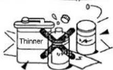
- Do not use alcohol, benzene, thinner, glass cleaner, polishing powder or other solvent for cleaning the unit because they can deteriorate and damage the air conditioner.
- Before cleaning the unit, be sure to turn off the main switch or circuit breaker to prevent injuries from the electric fan running inside.
- For details of the cleaning method, refer to "USUAL MAINTENANCE" and "SPECIAL MAINTENANCE" on pages 20 to 23.
- Do not put anything on or step on the indoor unit and outdoor unit. If you do so, it can topple over and cause an injury.
- To allow the air conditioner to operate at maximum performance, operate within the operating temperature range specified in the instructions. Failure to do so can cause a malfunction, break down, or water to leak from the unit.
- It is recommended that maintenance be performed by a specialist when the unit has been operated for a long time.

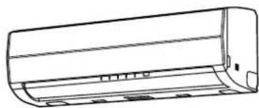
NAMES OF PARTS
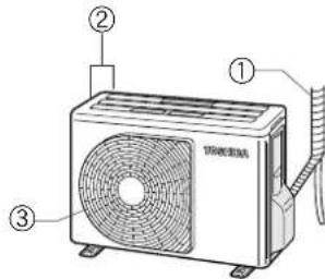
Outdoor unit
①Refrigerant connecting pipe and electric wires
②Air inlet (Side and rear)
③Air outlet
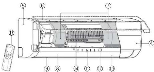
Indoor unit
④Room temperature sensor
⑤Front panel
⑥Air inlet grille
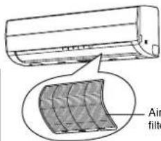
⑦Air filter
⑧Air outlet
⑨Horizontal air flow louver
Located at the back of the vertical air flow louver.
⑩Vertical air flow louver
⑪Display panel
⑫Infrared signal receiver
⑬Remote controller
⑭Plasma pure filter
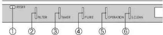
NAMES AND FUNCTIONS OF INDICATORS AND CONTROLS ON INDOOR UNIT
Display panel
The operating states are shown below.
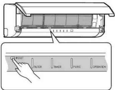
①RESET button
②FILTER indicator (Orange)
③TIMER indicator (Yellow)
④PURE indicator (Blue)
⑤OPERATION indicator (Green)
The operation indicators flash rapidly (5 times per second) when a safety protection feature is activated.
⑥S.CLEAN indicator (Green)
When the unit shuts down after having operated for 10 or more minutes in the cooling or dry mode, the cleaning operation is started automatically, and the S.CLEAN indicator turns on.
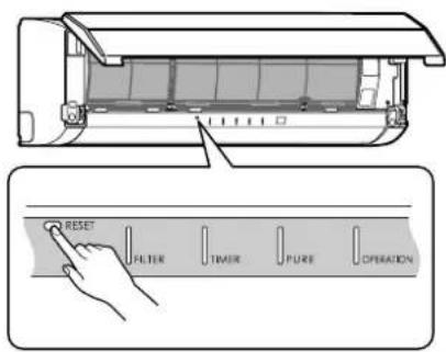
RESET button
The RESET button has the following two functions.
- Reset function
Use when the FILTER indicator (orange) is on. (see page 21.)
• Temporary operation function
Use when you misplace or lose the remote controller, or when its batteries are used up. (see page 19.)
flowchart
graph LR
    A["RESET"] --> B["FILTER"]
    B --> C["TIMER"]
    C --> D["PURE"]
    D --> E["OPERATION"]
    E --> F["S.CLEAN"]
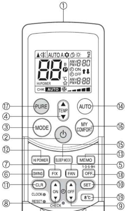
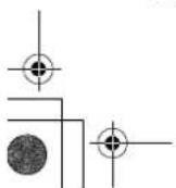
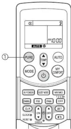
REMOTE CONTROLLER AND ITS FUNCTIONS
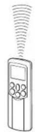
①Infrared signal transmitter
Transmits signals to the indoor unit.
② button
Press the button to start operation. (A receiving beep is heard.) Press the button again to stop operation. (A receiving beep is heard.) If no receiving sound is heard from the indoor unit, press the button again.
③Mode select button (MODE)
Press this button to select a mode. Each time you press the button, the modes cycle in order from A: Auto changeover control, COOL, DRY, HEAT and back to A. (A receiving beep is heard.)
④Temperature button ( )
▲ .. The temperature setting is raised to 30°C.
▼ ... The temperature setting is lowered to 17°C. (A receiving beep is heard.)
⑤Fan speed button (FAN)
Press this button to select the fan speed. When you select AUTO, the fan speed is automatically adjusted according to the room temperature. You can also manually select the desired fan speed from five available settings.
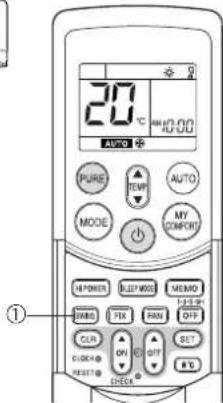
⑥Auto louver button (SWING)
Press this button to swing the louver. (A receiving beep is heard.) Press the button again to stop the louver from swinging. (A receiving beep is heard.) (see page 16.)
⑦Set louver button (FIX)
Press this button to adjust the air flow direction. (A receiving beep is heard.) (see page 16.)
⑧ON timer button (ON)
Use this button to change the clock and ON timer times.
To move up the time, press ▲ of the ON ▼ button.
To move down the time, press ▼ of the ON □ button.
⑨OFF timer button (OFF)
Use this button to change the OFF timer times.
To move up the time, press ▲ of the OFF ▲ button.
To move down the time, press ▼ of the OFF ▼ button.
⑩Reserve button (SET)
Press this button to store the time settings. (A receiving beep is heard.)
⑪ Cancel button (CLR)
Press this button to cancel the ON timer and OFF timer. (A receiving beep is heard.)
⑫High power button (Hi POWER)
Press this button to start high power operation. (see page 18.)
⑬Memory button (MEMO)
Press this button to ready for storing the settings. Hold down the button for 3 seconds or more to store the setting indicated on the remote controller and until the P mark is displayed. (see page 15.)
⑭Automatic operation button (AUTO)
Press this button to operate the air conditioner automatically.
(A receiving beep is heard.) (see page 18.)
⑮SLEEP MODE button
Press this button to start sleep mode. (see page 18.)
⑯MY COMFORT button
Press this button to operate the air conditioner according to the settings stored using the MEMO button. (see page 15.)
⑰PURE button (PURE)
Press this button to start the electrical air purifying operation. Press the button again to stop operation.
⑱Off timer button (OFF)
Press this button to start the OFF timer operation. You can select the OFF timer time from among four settings (1, 3, 5 or 9 hours).
⑲8°C operation button (8°C)
Press this button to start the 8°C set temperature heating operation. (see page 10.)
NAMES AND FUNCTIONS OF INDICATORS ON REMOTE CONTROLLER
Display
All indicators, except for the clock time indicator, are displayed by pressing the button.
①Transmission mark
This transmission mark (▲indicates when the remote controller transmits signals to the indoor unit.
②Mode indicator
Indicates the current operation mode.
(AUTO: Automatic control, A: Auto changeover control, COOL, DRY, ⚙ : HEAT)
③Temperature indicator
Indicates the temperature setting (17°C to 30°C).
④PURE indicator
Shows that the electrical air purifying operation is in progress.
⑤FAN speed indicator
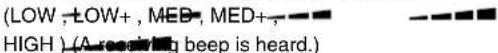
Indicates the selected fan speed. AUTO or one of five fan speed levels (LOW—, LOW+—, MED—■, MED+—■, HIGH—■) can be shown. Indicates AUTO when the operating mode is either AUTO or DRY.
⑥TIMER and clock time indicator
The time setting for timer operation or the clock time is indicated. The current time is always indicated except during TIMER operation.
⑦Hi POWER indicator
Indicates when Hi POWER operation starts. Press the Hi POWER button to start and press it again to stop operation.
⑧ P (MEMORY) indicator
Flashes for 3 seconds when the MEMO button is pressed during operation. The Ⓟ mark is shown when holding down the button for 3 seconds or more while the mark is flashing. Press another button to turn off the mark.
⑨SLEEP MODE indicator
Indicates when the SLEEP MODE is activated. Press the SLEEP MODE button to start and press it again to stop operation.
⑩A. B change indicator remote controller
- When the remote controller switching function is set, "B" appears in the remote controller display. (When the remote controller setting is "A", there is no indication at this position.) Remote controller switching function
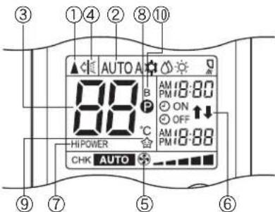
- In the illustration, all indicators are shown for purposes of explanation. During operation, only the relevant indicators are shown on the remote controller.
- If two indoor units are installed in the same room or adjoining rooms, both units may start and stop at the same time when the remote controller is operated. This can be prevented by setting the switching function so that each indoor unit is operated only by the corresponding remote controller.
• To use the remote controller switching function, contact the air conditioner dealer or the installation company.
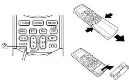
PREPARATION AND CHECK BEFORE USE
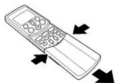
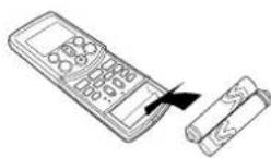
Loading the remote controller batteries
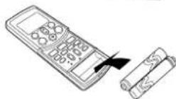
①Remove the cover, and insert the batteries.
②Press the RESET button.
The clock time indicator flashes. Press the RESET button using an object with a narrow tip.
③Reattach the cover.
Batteries
• To replace the batteries, use two new batteries (AAA type).
- The batteries will last about one year under normal usage.
- Replace the batteries if there is no receiving beep from the indoor unit or when the air conditioner cannot be operated using the remote controller.
• To avoid malfunctions due to battery leakage, remove the batteries when not using the remote controller for over one month.
- Slide off the cover while pressing the sides.
- Battery replacement
Be careful not to reverse the (+) position and the (−) position.
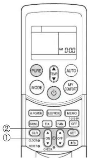
Setting the clock
Before you start operating the air conditioner, set the clock of the remote controller using the procedures given in this section. The clock panel on the remote controller will indicate the time regardless of whether the air conditioner is in use or not.
Initial setting
When batteries are inserted in the remote controller, the clock panel displays AM 0:00 and flashes.
Press the ON button to set the current time.
Each press of the ON button changes the time in one minute increments. Holding down the ON button changes the time in ten minute increments.
②SET SET button
Press the SET button.
The current time is displayed and the clock starts.
Adjusting the clock
①CLOCK button
Press the CLOCK button.
The clock time indicator flashes.

Press the ON button to set the current time.
Each press of the ON button changes the time in one minute increments. Holding down the ON button changes the time in ten minute increments.
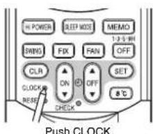
③SET SET button
Press the SET button.
The current time is displayed and the clock starts.
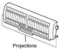
Check that the air filter and the plasma pure filter are correctly installed
- Press the plasma pure filter until the projections on both sides are fully inserted into the holders (tabs). If the installation is not correct, the FILTER indicator (orange) may come on.
- The air conditioner will not operate if curtains, doors or other objects block the signals from the remote controller to the indoor unit.
- Be careful that liquids do not spill onto the remote controller.
- Do not expose the remote controller to direct sunlight or heat. If the infrared signal receiver on the indoor unit is exposed to direct sunlight, the air conditioner may not function properly. Use curtains to prevent sunlight from reaching the receiver.
- Signals may not be properly received, if the room using the air conditioner has fluorescent lighting with electronic starters. If you plan to use fluorescent lamps, consult with your local dealer.
- If other electrical appliances are activated by the remote controller, move these appliances or consult with your local dealer.
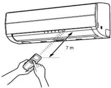
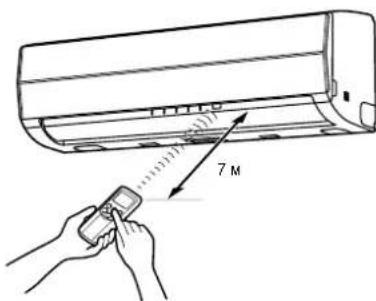
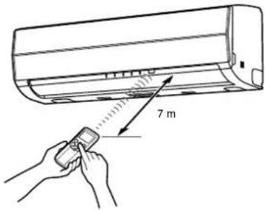
Location of the remote controller
- Keep the remote controller where its signals can reach the receiver of the indoor unit (a distance of up to 7 m is allowed).
- When you select timer operation, the remote controller automatically transmits a signal to the indoor unit at the specified time.
If you keep the remote controller in a location where proper signal transmission is blocked, a time lag of up to 15 minutes may occur.
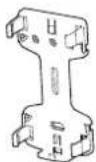
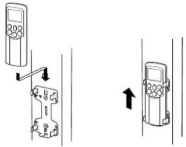
Remote controller holder
Installing the remote controller holder
- Before you actually install the remote controller holder on a wall or pillar, check whether the remote controller signals can be received by the indoor unit.
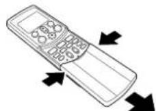
Mounting and removing the remote controller
- To mount the remote controller, hold it parallel to the remote controller holder and push it in fully. To remove the remote controller, slide the remote controller upwards and out from the holder.


natural_image
Line drawing of a cylindrical air conditioner unit (no text or symbols)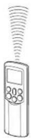
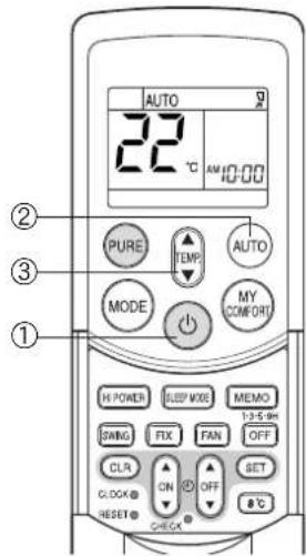
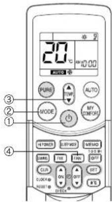
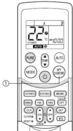
AUTOMATIC OPERATION
When you set the air conditioner to AUTO mode, it automatically selects cooling, heating, or fan only operation depending on the room temperature. (see page 18.)
The fan speed and louver are also automatically controlled.
Start
① button
Press this button to start the air conditioner.
②AUTO button (AUTO)
Press AUTO button.
③Temperature button ( ) TEMP
Set the desired temperature.
- The OPERATION indicator (green) on the display panel of the indoor unit lights. The operating mode is selected according to the room temperature and operation starts after approximately 3 minutes.
- If the AUTO mode is uncomfortable, you can select the desired conditions manually. The fan speed and louver position can be changed, and MODE is also changed from AUTO to A when the fan speed or louver position is changed. The fan speed indicator is also shown.
Stop
button
Press this button again to stop the air conditioner.
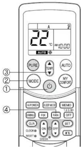
When you set the air conditioner to A mode or switch over from AUTO operation because of a change in settings, the air conditioner automatically selects cooling, heating, or fan only operation depending on the room temperature. (see page 18.)
Start
① button
Press this button to start the air conditioner.
②Mode select button (MODE)
Select A.
③Temperature button ( )
Set the desired temperature.
④Fan speed button (FAN)
Select one of "AUTO" LOW, LOW+, MED-, MED+, HIGH
- The OPERATION indicator (green) on the display panel of the indoor unit lights. The operating mode is selected according to the room temperature and operation starts after approximately 3 minutes.
- The temperature, fan speed and louver position can be changed. You can select the desired conditions manually.
Stop
button
Press this button again to stop the air conditioner.
EN
8

Press this button to start the air conditioner.
②Mode select button (MODE)
Select COOL or HEAT.
③Temperature button ( ) TEMP
Set the desired temperature.
④Fan speed button (FAN)
Select one of "AUTO" LOW—, LOW+—, MED—■, MED+—■■, HIGH—■■.
- The OPERATION indicator (green) on the display panel of the indoor unit turns on. Operation starts after approximately 3 minutes.
Stop
button
Press this button again to stop the air conditioner.
DRY OPERATION
Start
① button
Press this button to start the air conditioner.
②Mode select button (MODE)
Select DRY
③Temperature button ( )
Set the desired temperature.
- The fan speed setting is fixed to AUTO and the AUTO is displayed.
- The OPERATION indicator (green) on the display panel of the indoor unit turns on, and operation starts after approximately 3 minutes.
Stop
button
Press this button again to stop the air conditioner.
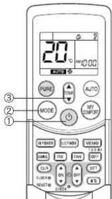
8°C OPERATION
Press this button to start the 8°C set temperature heating operation.
The air conditioner controls the room temperature to about 8°C.
The room temperature may deviate slightly from 8^ C depending on the size of the room and the installation condition of the unit.
Starting the 8°C heating operation while the air conditioner is stopped
Start
①8°C button
Press this button to start the 8°C set temperature heating operation.
- The OPERATION indicator (green) on the display panel of the indoor unit turns on. Operation starts after approximately 3 minutes.
Stop
button
Press this button to stop the air conditioner.
If the 8°C heating operation starts while the air conditioner is stopped, press the 8°C button again to stop the operation.
Starting the 8°C heating operation while the air conditioner is operating
Start
①8°C button
Press this button to change to the 8°C set temperature heating operation.
- If the air conditioner performs a cooling (including automatic cooling) or dry operation, it stops and the 8°C set temperature heating operation starts after approximately 3 minutes. If the air conditioner performs a heating operation, it changes immediately to the 8°C heating operation.
- If the air conditioner performs a PURE operation, it performs both the pure operation and 8^ heating.
Stop
button
Press this button to stop the air conditioner.
If the 8°C heating operation starts while the air conditioner is operating, press the 8°C button again to return to the previous operating condition.
Check the operating condition on the screen of the remote control.
When a heating operation starts from 8°C heating, it can take approximately 5 minutes for the warm air to start blowing.
CAUTION
The heating performance could worsen if the louver direction is too high during 8°C heating operation.
NOTE
- The fan speed at the start of 8^ heating is operated with AUTO.
- If a timer operation is set to before the 8°C heating operation, the timer operation setting is cancelled. Timer operation settings cannot be made during 8°C heating operation.
- Settings for SWING (louver swing), FIX (louver position), FAN (fan speed) and PURE (pure operation) can be changed during 8^ heating operation. Setting changes cannot be made with other buttons.
- The temperature of the blown air is lower than during normal heating operation.
PURE OPERATION
Press this button to start the electrical air purifying operation.
During air conditioner operation
①PURE button
PURE operation starts by pressing this button.
- The PURE indicator (blue) on the display panel of the indoor unit turns on.
- Plasma pure filter is activated.
To stop only PURE operation
PURE button
PURE operation stops by pressing this button.
- The PURE indicator (blue) on the display panel of the indoor unit turns off.
- Plasma pure filter is deactivated.
To stop air conditioner operation at the same time
button
Air conditioner operation and PURE operation stop by pressing this button.
- The OPERATION indicator (green) and PURE indicator (blue) on the display panel of the indoor unit turn off.
CAUTION
- When the ⏻ button is pressed the next time, operation starts with the combined air conditioner and PURE operation.
- During the combined air conditioner and PURE operation, air conditioner operation only cannot be stopped.
When the air conditioner is stopped
①PURE button
PURE operation starts by pressing this button.
- The PURE indicator (blue) on the display panel of the indoor unit turns on.
INFORMATION
- During PURE operation, a small amount of ozone is produced, and you might notice the smell.
- When the air flow is automatic, it changes between LOW and MED+ LOW — operation is performed when the indoor air becomes clean. During operation, the position of the vertical air flow louvers may change if the room temperature is low.
- Opening the air inlet grille during PURE operation sometimes turns on the FILTER indicator (orange). In this case, stop PURE operation (stop the air conditioner if it is also operating), and then close the air inlet grille.
- The FILTER indicator (orange) turns on after PURE operation is performed for about 1000 hours. When the indicator turns on, clean the plasma pure filter. (see page 22.)


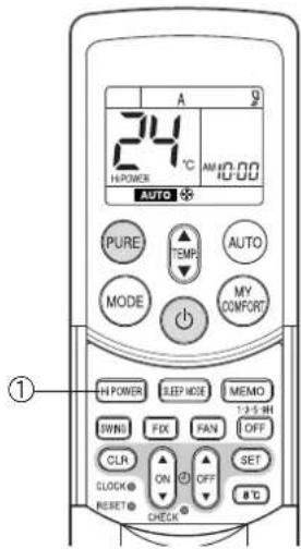
Hi POWER OPERATION
High power (Hi POWER)
- The Hi POWER (high power operation) mode automatically controls room temperature, air flow and the operation mode so that the room is quickly cooled in summer and warmed in winter. ( ^2 see page 18.)
Setting Hi POWER mode
①Hi POWER button
Press the Hi POWER button. The Hi POWER mark on the remote controller is shown.
Canceling Hi POWER mode
①Hi POWER button
Press the Hi POWER button once again. The Hi POWER mark on the remote controller turns off.
CAUTION
The Hi POWER mode cannot be activated during DRY operation.
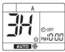
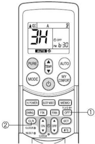
1, 3, 5, 9H OFF TIMER
The air conditioner stops after operating for the set time (1, 3, 5 or 9 hours).
①OFF button
Press the OFF button (during operation).
- There is a short beep and the timer indicator comes on. The time at which the air conditioner will stop is indicated on the remote controller display (1H: about 1 hour after the current time).
- Press the button again while 1H is displayed (about 3 seconds) to change to the 3H indicator, press again to change to the 5H indicator, and press again to change to the 9H indicator.
- After selecting the time you want, do not press this button again. (When the 1H, 3H, etc. indicator goes off the timer is set.)
②CLR button
Press the CLR button to cancel the timer.
- The timer is canceled but the air conditioner continues to operate.
- The 1, 3, 5 or 9H OFF timer operation is also canceled if the OFF button is pressed after making a setting.
INFORMATION
- Cleaning operation starts when the time of the 1, 3, 5 or 9H OFF timer is reached. (Cleaning operation is not performed during heating operation or the PURE operation.)
- When using in combination with the ON timer, first set the 1, 3, 5 or 9H OFF timer and then set the ON timer.
- If the OFF button is pressed while the ON (OFF) timer has been set, the ON (OFF) timer is canceled and only the 1, 3, 5 or 9H OFF timer is set.
EN
12
TIMER OPERATION
ON timer and OFF timer
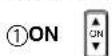
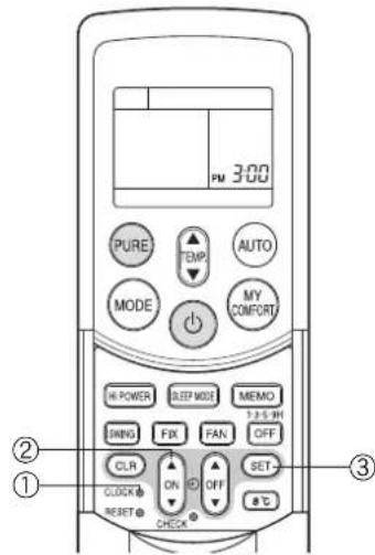
Setting the ON Timer
①ON

button
Press the ON button. Set the timer to the desired time. Each time the ON button is pressed, the time changes in ten minute increments. Holding down the ON button changes the time in one hour increments.
②SET

button
Press the SET button to set the timer. The timer time is displayed, and the timer starts.
③CLR

button
Press the CLR CLR button to cancel the timer setting.
Setting OFF Timer
①OFF

button
Press the OFF button.
Set the timer to the desired time. Each time the OFF button is pressed, the time changes in ten minute increments. Holding down the OFF button changes the time in one hour increments.
②SET

button
Press the SET button to set the timer. The timer time is displayed, and the timer starts.
③CLR

button
Press the CLR CLR button to cancel the timer setting.
CAUTION
- When you select timer operation, the remote controller automatically transmits the timer signal to the indoor unit at the specified time. Therefore, keep the remote controller in a location where it can transmit the signal to the indoor unit properly.
- If you do not press the SET Ⓜ button within 30 seconds after setting the time, the setting will be cancelled.
Once you select timer operation mode, the settings are saved in the remote controller.
Thereafter, the air conditioner will start operating under the same conditions as you pressed the ON or CRT button on the remote controller.
You cannot set the timer when the clock display is flashing.
Follow the instructions in the section "Setting the clock" on page 6 to set the clock, and then set the timer.


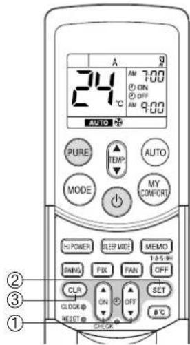
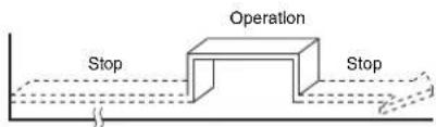
Combined timer (Setting the ON and OFF timers simultaneously)
OFF timer → ON timer
(Operation -> Stop -> Operation)
This feature is useful when you want to stop the air conditioner after you go to sleep, and start it again in the morning when you wake up or you return home.
Example:
To stop the air conditioner and start it again next morning
Setting combined TIMER
(1) Press the OFF button to set the OFF timer.
(2) Press the ON button to set the ON timer.
(3) Press the SET button.

flowchart
graph LR
    A["Operation"] --> B["Stop"]
    B --> C["Operation again"]
ON timer → OFF timer
(Stop → Operation → Stop)
You can use this setting to start the air conditioner when you wake up and stop it when you leave the house.
Example:
To start the air conditioner the next morning and stop it
Setting combined TIMER
(1) Press the ON button to set the ON timer.
(2) Press the OFF button to set the OFF timer.
(3) Press the SET button.
- The ON or OFF timer function that is closer to the current time is activated first.
- If the same time is set for both ON and OFF timers, no timer operation is performed. Also, the air conditioner may stop operating.
CAUTION
Approximately 3 seconds later, the remote controller will transmit the signal to the indoor unit and a receiving beep will sound from the indoor unit after you press the SET button.
Daily combined timer (setting the ON and OFF timers simultaneously and activating every day)
This feature is useful when you want to use the combined timers at the same time every day.
Setting combined TIMER
(1) Press the ON button to set the ON timer.
(2) Press the OFF button to set the OFF timer.
(3) Press the SET button.
(4) After step (3), an arrow mark (or) flashes for about 3 seconds. Press the SET button during this flashing.
- Both arrows (,↑) are shown while the daily timer is activated.
Cancelling timer operation
Press the CLR button.
Clock display
During TIMER operation (ON-OFF, OFF-ON, OFF timer), the clock time indicator is not shown so the setting time can be displayed. To view the current time, press the SET button briefly and the current time will be displayed for about 3 seconds.

EN
14

Use the MEMO button to store a frequently used operation setting for convenience. Start the air conditioner in the operation mode that you want the remote controller to store.
Press the button as shown below while the air conditioner is operating.
①MEMO button
Press this button briefly to ready for storing the setting.
All the icons currently shown flash, except for the clock time indicator and mode indicator.
②MEMO button
Hold down the MEMO button for 3 seconds or more while the indicator flashes. The mark is shown and the setting is stored.
- If you do not press the MEMO button within 3 seconds or if you press another button, the MEMORY setting is cancelled.
- Operation modes which can be stored with the MEMO button are MODE, Temperature, FAN, TIMER and Hi POWER.

To operate the air conditioner with the setting stored using the MEMO button.
①MY COMFORT button
Press the MY COMFORT button. The setting stored with the MEMO button will be shown and the air conditioner operates based on the setting.
(A): When the MY COMFORT button is pressed while operation is stopped
(B): When the MY COMFORT button is pressed during operation
- The OPERATION indicator (green) on the display panel of the indoor unit turns on, and operation starts after approximately 3 minutes.
- The operation mode changes to the setting stored with the MEMO button.
- Initial setting:
MODE: AUTO
Temperature : 22
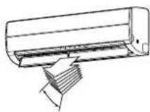
ADJUSTING AIR FLOW DIRECTION
- Adjust the air flow direction properly. Failure to do so could cause discomfort and make an uneven room temperature distribution.
- Adjust the vertical air flow using the remote controller.
- Adjust the horizontal air flow manually.
Adjusting the vertical air flow
The air conditioner automatically adjusts the vertical air flow direction according to the operating conditions when AUTO or A mode is selected.
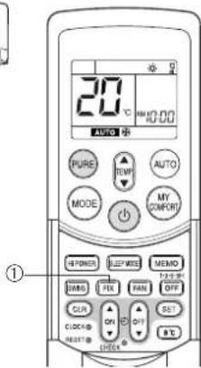
To set a selected air flow direction
Use this function when the air conditioner is operating.
①FIX button
Hold down or briefly press the FIX button on the remote controller to move the louver in the desired direction.
- Change the vertical air flow louver direction within the range indicated.
- In subsequent operations, the vertical air flow is automatically set to the direction that you set the louver using the FIX button.
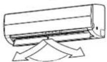
To automatically swing the air flow direction
Perform this function when the air conditioner is operating.
①SWING button
Press the SWING button on the remote controller.
- To stop the function, press the SWING button.
- To change the swing direction, press the FIX button.
CAUTION
- The FIX and SWING buttons will be disabled when the air conditioner is not operating (including when ON TIMER is set).
- Do not operate the air conditioner for an extended period of time with the air flow direction set downward during the cooling or dry operation. Otherwise, condensation may occur on the surface of the vertical air flow louver and cause water dripping.
- Do not move the vertical air flow louver manually. Always use the FIX button. If you move the louver manually, it may malfunction during operation. If the louver malfunctions, stop the air conditioner once, and restart.
- When the air conditioner is started immediately after it was stopped, the vertical air flow louver might not move for about 10 seconds.
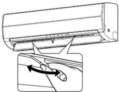
Adjusting the horizontal air flow
Preparation:
- Grasp the lever on the horizontal air flow louver and move them to adjust the air flow direction as required.
- You can adjust the air flow at the left and right locations of the grilles.
natural_image
Diagram showing airflow or fluid flow from a car air conditioner into a vehicle, with an inset illustrating the motion of airflow direction (no text or symbols present)This air conditioner is equipped with an automatic restarting function which allows the air conditioner to resume without the use of the remote controller under the operating settings in the event of a power shutdown. Operation resumes without warning 3 minutes after power is restored.
INFORMATION
The AUTO RESTART OPERATION is not set to work at factory shipment, and so it is necessary to set it to this function if required.
HOW TO SET AUTO RESTART
To set the auto restart function, proceed as follows:
The power supply to the unit must be on. The function will not be set if the power is off.
To enable the auto restart function, hold down the RESET button for 3 seconds.
The air conditioner receives the setting and beeps 3 times. The system now restarts automatically. The auto restart setting is activated.
(1) When the air conditioner is in stand-by (not running).
Hold down the RESET button for 3 seconds or more.
- The air conditioner starts to operate. The green indicator turns on.
• After about 3 seconds, the air conditioner beeps 3 times.
The green indicator flashes for 5 seconds.
• The air conditioner is operating.
If the air conditioner is not required to run at this time, push the RESET button again or use the remote controller to stop the air conditioner.
(2) When the air conditioner is operating.
Hold down the RESET button for 3 seconds or more.
• The air conditioner stops operating. The green indicator turns off.
- 3 seconds after pushing the button, the air conditioner beeps 3 times.
The green indicator flashes for 5 seconds.
• The air conditioner stops.
If you do not need the air conditioner to stop at this time, use the remote controller to restart the air conditioner. During the subsequent operation, the green indicator is turned on.
- The auto restart operation will not accept a command if timer operation with the remote controller is activated.
• After restarting the air conditioner by the AUTO RESTART OPERATION, the louver swing (AUTO) operation resumes.
HOW TO CANCEL AUTO RESTART
To cancel the auto restart operation, proceed as follows:
Repeat the setting procedure. The air conditioner receives the setting and beeps 3 times.
The air conditioner now needs to be manually restarted with the remote controller after the main supply is turned off.
The auto restart setting is cancelled.
(1) When the air conditioner is in stand-by (not running).
Hold down the RESET button for 3 seconds or more.
• The air conditioner starts to operate.
The green indicator will turn on.
• After about 3 seconds, the air conditioner beeps 3 times.
• The air conditioner is operating.
If the air conditioner is not required to run at this time, push the RESET button again or use remote controller to stop the air conditioner.
(2) When the air conditioner is operating.
Hold down the RESET button for 3 seconds or more.
• The air conditioner stops operating.
The green indicator is turned off.
• After about 3 seconds, the air conditioner beeps 3 times.
• The air conditioner stops.
If you do not need the air conditioner to stop at this time, use the remote controller
to restart the air conditioner.
During subsequent operation, the green indicator is turned on.
RESET button
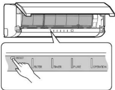
RESET button
HOW THE AIR CONDITIONER WORKS
Automatic Operation
As shown in Figure 1, Automatic Operation mode selects the operation based on the room temperature data (Ta) when operation begins.
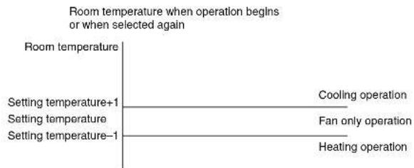
Figure 1
The operation mode is selected again after the compressor has remained stopped for 15 minutes.
Hi POWER operation
When you press the Hi POWER button during cooling, heating or A operation, the air conditioner starts the following operation.
• Cooling operation
The cooling operation is performed at 1°C lower than the temperature setting.
The fan speed is also set to high*.
* The noise level raises, according to the fan speed.
• Heating operation
The heating operation is performed at 2°C higher than the temperature setting.
The fan speed is automatically switched according to the operating condition.
SLEEP MODE operation
The air conditioner automatically controls the room temperature, air flow and noise level, to prevent overcooling in summer and maintain a warm and comfortable room in winter.
INFORMATION
- The power and noise level are reduced during sleep mode, so the room may not be cooled (or heated) sufficiently if the mode is used for a long period of time.
- The sleep mode cannot be used during dry operation or PURE operation (independent operation).
(PURE operation (independent operation) is when the PURE button is pressed while the air conditioner is stopped to perform PURE operation by itself. The air conditioner does not operate at this time.) - If the FAN button is pressed during sleep mode, the sleep mode is canceled.
- Sleep mode is not a timer operation.
Dry operation ( )
The dry mode automatically selects the cooling dry operation based on the difference between the temperature setting and the actual room temperature.
The fan speed indicator shows AUTO, and low speed is used.
EN
18
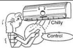
Maintain room temperature at a comfortable level
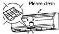
Clean the air filters
Clogged air filters impair the performance of the air conditioner. Clean them every two weeks.
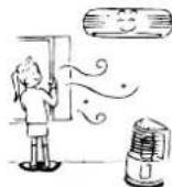
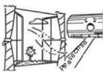
Never open doors and windows more than necessary
To keep cool or warm air in the room, never open doors and windows more than necessary.
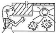
Window curtains
During cooling operation, close the curtains to avoid direct sunlight. During heating operation, close the curtains to keep the heat in.
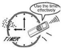
Use the timer effectively
Set the timer for the desired operating time.
Allow uniform circulation of room air
Adjust the air flow direction for even circulation of room air.
Blows upward

Blows downward
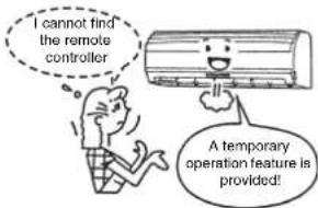
TEMPORARY OPERATION
Temporary operation
This function is used to operate the unit temporarily in case you misplace the remote controller or the batteries are used up.
- Push the RESET button to start the automatic operation (AUTO).
- While the temporary operation is activated, the remote controller operation is disabled.
- Hold down the button for 10 seconds to start the cooling operation.
CLEANING OPERATION
Cleaning operation
This function is used to dry the inside of the air conditioner to reduce the growth of mold, etc. inside the air conditioner.
- When the unit shuts down after having operated for 10 or more minutes in the cooling or dry mode, the cleaning operation is started automatically, and the S.CLEAN indicator on the unit's display panel turns on.
Cleaning operation duration
- The cleaning operation lasts for 4 hours if the unit has been operating in the cooling or dry mode for 10 minutes or more.
About the cleaning operation
- The cleaning operation will not make the room cleaner or remove the mold and dust already inside the air conditioner.
- During operation, a small amount of frost may be visible: this is normal and does not indicate a malfunction.
• The vertical airflow louvers open slightly. - If an ongoing cleaning operation is suspended, the effect of the cleaning will be compromised.
- To forcibly stop the cleaning operation, press the button twice during the cleaning operation.


USUAL MAINTENANCE
WARNING
Before you clean the air conditioner, be sure to turn off the circuit breaker or main power switch.
Cleaning of indoor unit and remote controller
CAUTION
- Use a dry cloth to wipe the indoor unit and remote controller.
- When the air conditioner is extremely dirty, use a cloth dipped in cold water to wipe the indoor unit.
- Never use a damp cloth on the remote controller.
- Do not use a chemical-based duster for wiping or leave such materials on the unit for extended periods of time. Doing so could damage or cause the surface of the unit to fade.
- Do not use benzine, thinner, polishing powder, or other solvents for cleaning. These can cause the plastic surface to crack or deform.
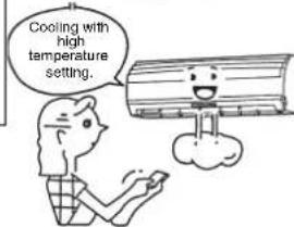
When not using the unit for at least 1 month
(1) Perform fan operation for 3 to 4 hours to dry the inside of the unit.
- If a high temperature setting is used with cooling operation, fan operation is performed.
(2) Stop the air conditioner and turn off the circuit breaker.
(3) Clean the air filters.
(4) Remove the batteries from the remote controller.
Check before operation
CAUTION
- Check that the air filters are installed.
- Check that the air outlet and inlet of the outdoor unit are not blocked.
Cleaning the air filter
Clean the air filters every 2 weeks. The performance of the air conditioner will degrade if the air filters are covered with dust.
Clean the air filters as often as possible.
Preparation:
- Turn off the air conditioner using the remote controller.
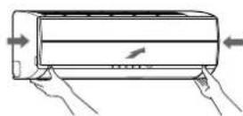
- Open the air inlet grille.
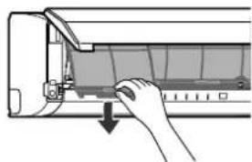
1 Open the air inlet grille. Lift the air inlet grille up to the horizontal position.
2 Grasp the left and right handles of the air filter and lift it up slightly, and then pull it downward to take it out from the filter holder.
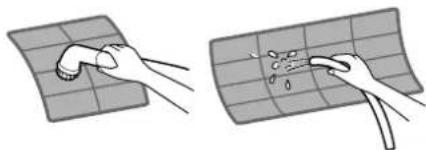
3 Use a vacuum cleaner to remove the dust from the filters or wash them with water. After washing the air filters, dry them in the shade.
natural_image
Two-step illustration showing hands cleaning a grid surface with a tool (no text or symbols)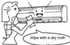

natural_image
Hand inserting a component into an air conditioner unit (no text or symbols visible)EN
20
4 Insert the top section of the air filter so that its right and left edges fit on the indoor unit and it is firmly set.
5 Close the air inlet grille.
* If the FILTER indicator on the indoor unit is shown, press the RESET button on the indoor unit to turn off the indicator.
Cleaning the air inlet grille
Preparation:
- Turn off the air conditioner using the remote controller.
- Open the air inlet grille.
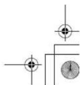
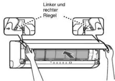
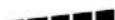
1 Remove the air inlet grille.
Hold the two sides of the air inlet grille and open upwards.
Remove the left (or right) arm by pushing it toward the outside and then pulling it toward you.
2 Wash it with water using a soft sponge or towel.
(Do not use a metallic scrubbing brush or other hard brushes.)
- Use of such hard objects will cause scratches on the surface of the grille and the metal coating to peel off.
- If extremely dirty, clean the air inlet grille with a neutral kitchen detergent and rinse it off with water.
3 Wipe off the water from the air inlet grille and dry it.
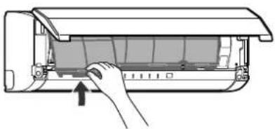
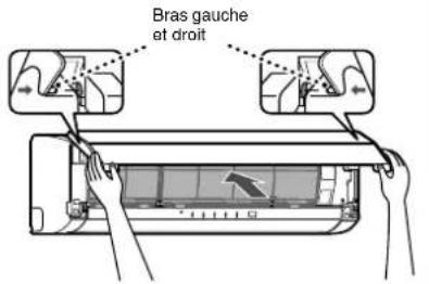
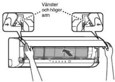
4 Fit the left and right arms of the air inlet grille to the shafts on the two sides of the air conditioner and push them in completely.
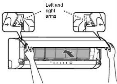
5 Pull the air inlet grille downward.
- Push the arrow locations (four) at the bottom of the air inlet grille to check that the grille is completely closed.
NOTE
Cleaning and maintenance of the indoor/outdoor units are strongly recommended for air conditioning systems which are used regularly.
Failure to clean the indoor/outdoor units regularly will result in poor cooling performance, icing, water leakage and even premature compressor failure.
natural_image
Diagram of a hand inserting a component into an air conditioner unit (no text or symbols visible)
natural_image
Illustration of hands installing or adjusting a wall-mounted air conditioner (no text or symbols present)SPECIAL MAINTENANCE
Cleaning the plasma pure filter
Preparation:
- Turn off the air conditioner using the remote controller.
- Turn off the power supply.
- Clean the plasma pure filter when the FILTER indicator (orange) turns on. (This indicator turns on after PURE operation of about 1000 hours.)
- After cleaning is finished, push the RESET button on the indoor unit.
- Perform cleaning every six months or so.
- Even if the FILTER indicator does not turn on, clean the plasma pure filter whenever the unit makes a humming, clicking, or buzzing sound. If the indicator turns on during the night, the air conditioner can still be used until the morning without a problem, but be sure to perform cleaning as soon as possible.
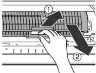
1 Open the air inlet grille.
Lift up the air inlet grille until it clicks into place.
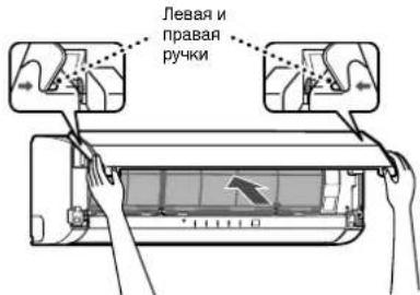
2 Grasp the left and right handles of the air filter and lift up slightly and then pull downward to remove the filter from the filter holder.
3 Take out the plasma pure filter.
- Grasp the handles, and then pull out as shown in ① and ②.
Checks after cleaning the plasma pure filter
- Confirm the FILTER indicator does not turn on by activating PURE operation for one hour or more.
- If the FILTER indicator turns on, recheck the following.
a) Fitting of the plasma pure filter
b) Fitting of the air inlet grille
And, reconfirm the FILTER indicator does not turn on by activating PURE operation for another one hour or more.
- In case the FILTER indicator does turn on, please call a service representative.
EN
22
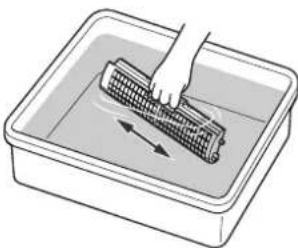
4 Wash and then dry.
(1) Soak in hot water at 40 to 50°C for about 10 to 15 minutes. If the staining is particularly severe, use a washing detergent compound (weak basic or neutral) at 10 to 15 times the standard concentration.
(2) Rub up and down, and rub left and right. Also, rub the surface gently with a sponge.
(3) Rinse with running water.
(4) Shake thoroughly, and allow the unit to drain.
(If oil or smoke strains are particularly hard to remove, repeat steps (1) to (4) 2 or 3 times.)
(5) Dry thoroughly in the shade.
natural_image
Illustration of a hand cleaning a corn cob in a rectangular basin (no text or symbols)CAUTION
- Never use any products marked as "bleach".
- Do not attempt to disassemble the unit.
- Do not rub with a scrubbing brush or similar implement.
- Do not utilize washing devices or equipment.
- Do not dry with a hair dryer or other appliance that uses hot air. (The heat can cause the unit to deform.)
- After cleaning, wait until the unit is completely dried before attaching. The FILTER indicator may turn on if the unit is used while wet.
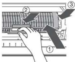
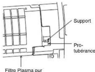
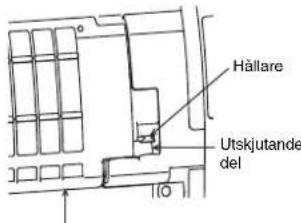
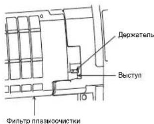
5 Attach the plasma pure filter.
- Grasp the handles, and then insert as shown in ①. Insert into the right and left guide rails, and then press in the direction of ② after it is all the way in.
- Press both ends of the plasma pure filter in the direction of ③ until the protrusions on both sides of the plasma pure filter are completely inserted into the holders.
Press in the plasma pure filter until the protrusions on both sides are completely inserted into the holders. If installation is incomplete, the FILTER indicator (orange) may light.
6 Attach the air filter, and then close the air inlet grille.
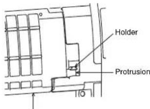
Plasma pure filter
AIR CONDITIONER OPERATION AND PERFORMANCE
Three-minute protection feature
A protection feature is provided that prevents the air conditioner from being activated for approximately 3 minutes when it is restarted immediately after operation or when the power supply switch is set to on. This is used to protect the machine.
Heating characteristics
Preheating operation
The air conditioner does not deliver warm air immediately after it is started.
Warm air flows out after approximately 5 minutes when the indoor heat exchanger has warmed up.
Warm air control
When the room temperature reaches the temperature setting, the fan indoor speed is automatically reduced.
The outdoor unit is stopped at this time.
Defrosting
If frost has formed on the outdoor unit during the heating operation, defrosting is started automatically (for approximately 5 to 10 minutes) to maintain the heating effect.
- The fans in both the indoor and outdoor units stop during the defrost operation.
- During the defrost operation, defrosted water is drained from the bottom plate of the outdoor unit.
Heating capacity
In the heating operation, heat is absorbed from outdoors and released into the room. That is called the heat pump system. When the outdoor temperature is too low, usage of another heating apparatus in combination with the air conditioner is recommended.
Consideration for accumulated snow
Select the position for the outdoor unit where it will not be subjected to snow drifts, accumulation of leaves or other seasonal debris. It is important that the air flow of the outdoor unit is not blocked as this will result in reduced heating or cooling performance. During the heating mode and at sub-zero temperatures, the water drained off the outdoor unit as a result of the automatic defrost may accumulate and freeze. It is important that adequate drainage or a soak-way be provided.
Power failure
Power failure during operation stops the unit completely.
- The OPERATION indicator (green) on the indoor unit starts flashing when power is restored.
- To restart operation, push the button on the remote controller.
- Lightning or a car wireless telephone operating nearby may cause the unit to malfunction. Turn the power supply switch off and then on again. Push the button on the remote controller to restart.
Air conditioner operating conditions
For proper performance, operate the air conditioner under the following temperature conditions.
| Cooling operation Outdoor temperature: | -10°C to 46°C |
| Room temperature: 21°C to 32°C | |
| CAUTIONRoom relative humidity — less than 80%. If the air conditioner operates outside this range, the surface of the air conditioner may attract condensation. | |
| Heating operation Outdoor temperature: | -15°C to 24°C |
| Room temperature: Less than 28°C | |
| Dry operation Outdoor temperature: -10°C to 46°C | |
| Room temperature: 17°C to 32°C | |
If the air conditioner is used in conditions other than above, the safety protection functions may be activated.
TROUBLESHOOTING
CAUTION
If any of the following conditions occur, stop the air conditioner immediately, turn off the main power switch and contact the dealer.
- The indicators flash at short intervals (5 Hz). Reset the circuit breaker 2 to 3 minutes after the power main switch is turned off. Despite the resetting operation, the indicators still continue turning on and off.
- The main power fuse often blows, or the circuit breaker is often activated.
- Foreign matter or water has fallen inside the air conditioner.
- Any other unusual conditions are observed.
Before asking for servicing or repairs, check the following points.
| Recheck | InoperativeThe power main switch is turned off.The circuit breaker is activated to cut off the power supply.The main power fuse has blown.The electric current has stopped.The batteries in the remote controller used up.The ON timer is set.As a protective mechanism for the air conditioner, it does not operate for 3 minutes immediately after restarting operation or turning on the main power. |   |
| Poor cooling or heating performanceThe air inlet or outlet of the outdoor unit is blocked.Doors or windows are opened.The air filter is clogged with dust.The louver is not at the correct position.The fan speed is set to low.The air conditioner is set to the DRY or SLEEP MODE.The temperature setting is too high (during cooling operation).The temperature setting is too low (during heating operation). |  | |
| These are not defects. | Condensation forms on the back of the indoor unit.Condensation on the back of the indoor unit is automatically collected and drained out. |  |
| Indoor unit or outdoor unit makes a strange noise.When the temperature changes sharply, the indoor or outdoor unit may make a strange noise (such as a tit-tack noise or flowing noise) because of the expansion/contraction of parts or change in refrigerant flow.The room air smells.A bad odor comes from the air conditioner.Smells absorbed in the wall, carpet, furniture, clothing, or furs are coming out.During PURE operation, a small amount of ozone is produced, and you might notice the smell. |   |
Before asking for servicing or repairs, check the following points.
The OPERATION indicator turns on and off.
- The indicator turns on and off (1 Hz) when power is restored after a power failure or when the power main switch is set to on. Reset the circuit breaker to ON.
Frost forms on the outdoor unit during heating operation.
Water is drained from the outdoor unit.
- Frost sometimes forms on the outdoor unit during heating operation. In that case, the unit automatically performs defrosting (for 2 to 10 minutes) for improving the heating efficiency.
- In the defrosting operation, the airflow from both the indoor and outdoor units stops.
- A hiss sound is heard when the flow of the refrigerant is changed for defrosting.
- The water resulting from automatic defrosting during the heating operation is drained from the outdoor unit.
The air flow changes even though the FAN button is not set to the AUTO mode.
- When the temperature of the blown air goes down during heating operation, the air conditioner automatically changes or stops the air flow from the indoor unit so that the people in the room do not feel chilly.
A white mist of chilled air or water is generated from the outdoor unit.
- Steam is sometimes generated from the indoor unit during cooling operation or the outdoor unit during defrosting operation.
Automatic operation of vertical air flow louvers
- When the room temperature or outdoor temperature is high during the heating operation, the vertical air flow louvers close once and then set themselves automatically to the original position setting again.
The FILTER indicator turns on.
- This indicator turns on after PURE operation has been performed for approximately 1000 hours.
- The indicator may turn on if the front panel is not firmly closed.
- The indicator may turn on if the plasma pure filter is not securely attached.
Sounds made from the indoor unit
- The plasma pure filter may make a humming, clicking, or buzzing sound when it is dirty.
- When the power is turned on or the air conditioner is stopped, the vertical air louvers may make a rattling sound or shuttling sound.
- Some parts may expand or shrink due to temperature fluctuations, and this can result in a slapping sound.
- When the refrigerant is flowing, a hissing sound or gurgling sound can result.
- A hissing sound can be made when the air conditioner is switched to defrosting operation during heating operation.
Sounds made from the outdoor unit
- A rustling sound can be made when the air conditioner is switched to defrosting operation during heating operation.
natural_image
Illustration of a person blowing a cup into a cylindrical container (no text or symbols)

EN
26

SPECIFICATIONS
| TypeReverse cycle, Split type | ||||||
| Model | Indoor Unit | Outdoor Unit | Indoor Unit | Outdoor Unit | ||
| RAS-10SKVP-ND | RAS-10SAVP-ND | RAS-13SKVP-ND | RAS-13SAVP-ND | |||
| Power supply | 220-240 V ~50 Hz | 220-240 V ~50 Hz | ||||
| Cooling capacity (kW) CAPA. | 2.5 | 3.5 | ||||
| Heating capacity (kW) CAPA. | 3.2 | 4.2 | ||||
| Cooling current (A) AMP. | 0.15 | 2.57-2.34 | 0.15 | 4.00-3.66 | ||
| Cooling power (W) WATT. | 30 | 460 | 30 | 820 | ||
| Heating current (A) AMP. | 0.15 | 3.15-2.87 | 0.15 | 4.40-4.02 | ||
| Heating power (W) WATT. | 30 | 600 | 30 | 920 | ||
| Dimensions | Width (mm) | 790 | 780 | 790 | 780 | |
| Height (mm) | 250 | 550 | 250 | 550 | ||
| Depth (mm) | 208 | 290 | 208 | 290 | ||
| Net weight (kg) | 9 | 38 | 9 | 38 | ||
| Type | Reverse cycle, Split type | |||||
| Model | Indoor Unit | Outdoor Unit | ||||
| RAS-16SKVP-ND | RAS-16SAVP-ND | |||||
| Power supply | 220-240 V ~50 Hz | |||||
| Cooling capacity (kW) CAPA. | 4.5 | |||||
| Heating capacity (kW) CAPA. | 5.5 | |||||
| Cooling current (A) AMP. | 0.15 | 6.18-5.65 | ||||
| Cooling power (W) WATT. | 30 | 1,320 | ||||
| Heating current (A) AMP. | 0.15 | 6.83-6.25 | ||||
| Heating power (W) WATT. | 30 | 1,460 | ||||
| Dimensions | Width (mm) | 790 | 780 | |||
| Height (mm) | 250 | 550 | ||||
| Depth (mm) | 208 | 290 | ||||
| Net weight (kg) | 9 | 38 | ||||
• These specifications are subject to change without notice for the purpose of incorporating technical improvements.
The specified air-conditioning performance is based on the data determined under the following conditions.
For cooling
| Air inlet temperature °C | |||
| Indoor coil assembly | Outdoor coil assembly | ||
| Dry bulb | Wet bulb | Dry bulb | Wet bulb |
| 27 | 19 | 35 | 24 |
For heating
| Air inlet temperature °C | |||
| Indoor coil assembly | Outdoor coil assembly | ||
| Dry bulb | Wet bulb | Dry bulb | Wet bulb |
| 20 | — | 7 | 6 |
INFORMATION
When the outside temperature drops, power is supplied to the de-icing heater of the outdoor unit even if the air conditioner is off. At this time the power consumption is approximately 100 W.
TROUBLESHOOTING (Remote Controller)
Before asking for servicing or repairs, check the following points.
| The remote controller does not operate correctly. | ||
| Symptoms Causes Possible Solution | ||
| The operating mode switches.• Check whether the MODE indicated on the display is AUTO. AUTO | The fan speed and louver direction cannot be changed in AUTO mode. When the SWING, FIX or FAN buttons are pressed in AUTO mode, the mode changes to A mode. | |
| The fan speed cannot be changed. | • Check whether the MODE indicated on the display isDRY. | When dry operation is selected, the air conditioner automatically selects the fan speed. The fan speed can be selected duringSOOL,HEAT, and A. |
| The Display Goes Off | ||
| Symptoms Causes Description | ||
| The indicators on the display are not shown after a short time. | ·Check whether the timer operation is over when the OFF TIMER is shown on the display. | The air conditioner stops since the setting time has elapsed. |
| The TIMER display turns off after a certain period of time. | ·Check whether the timer operation has started when the ON TIMER is shown on the display. | When the time reaches the time setting for the ON timer operation, the air conditioner starts to operate automatically and the ON timer display turns off. |
| The Signal Receiving Tone Does Not Sound | ||
| Symptoms Causes Description | ||
| No receiving tone is made from the indoor unit even when the ⏻ button is pushed. | • Check whether the infrared signal transmitter of the remote controller is properly pointed towards the receiver of the indoor unit when the ⏻ button is pushed. | Point the infrared signal transmitter of the remote controller towards the receiver of the indoor unit, and then press the ⏻ button repeatedly. |
ACCESSOIRES
natural_image
Illustration of two children painting a scroll with a smiling face (no text or symbols)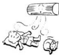
AVERTISSEMENTS CONCERNANT LE FONCTIONNEMENT
natural_image
Cartoon illustration of two children reacting to a large mechanical device, one striking the screen (no text or symbols present)AVERTISSEMENTS CONCERNANT LE DEPLACEMENT ET LES REPARATIONS
NOM ET FONCTION DES TEMOINS ET COMMANDES DE L'UNITE INTERIEURE
Panneau d'affichage
FR
4
NOM ET FONCTION DES INDICATEURS DE LA TELECOMMANDE
Affichage
Piles
③Touche SET SET
FONCTIONNEMENT AUTOMATIQUE
MINUTERIE D'ARRET (OFF) 1, 3, 5, 9H
MODE MEMOIRE/CONFORT
natural_image
Diagram showing airflow direction of a car air conditioner inside a duct (no text or symbols)FONCTION DE REDEMARRAGE AUTOMATIQUE
natural_image
Illustration of a hand pressing down on a partially open air conditioner cover (no text or symbols visible)
natural_image
Two hand-drawn diagrams showing surface cleaning or damage, with no text or symbols present.FR
20


natural_image
Diagram of a hand inserting a component into an air conditioner unit (no text or symbols visible)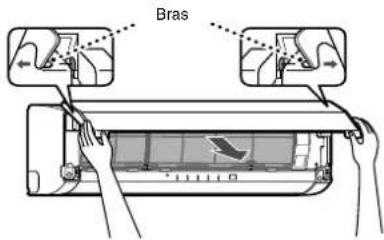
natural_image
Illustration of hands installing or adjusting a wall-mounted air conditioner (no text or symbols present)ENTRETIEN SPECIAL
natural_image
Illustration of a hand cleaning a woven mat in a rectangular basin with directional arrows (no text or symbols)ATTENTION
FONCTIONNEMENT ET PERFORMANCES DU CLIMATISEUR
natural_image
Cartoon illustration showing a man watching TV and a dog watching (no text or symbols)natural_image
Illustration of a person blowing a large cylindrical object with steam, next to another smaller cylindrical object (no text or symbols)natural_image
Illustration of two children on a ladder, one holding a sign with a smiling face (no text or symbols present)WARNUNG
WARNHINWEISE ZUR INSTALLATION
natural_image
Cartoon illustration of two children reacting to a TV screen showing a broken-out film (no text or symbols present)WARNHINWEISE ZUM BEWEGEN UND REPARATUR DES GERÄTS
natural_image
Line drawing of a remote control with directional arrows indicating rotation (no text or symbols)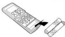
Batterien

natural_image
Line drawing of a rectangular air conditioner unit (no text or symbols)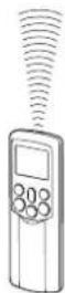
AUTOMATIKBETRIEB
VORSICHT
natural_image
Diagram of a car air conditioner unit with airflow direction arrow (no text or symbols)AUTOMATISCHER NEUSTART
natural_image
Two-step illustration showing hands cleaning a grid surface with a tool (no text or symbols)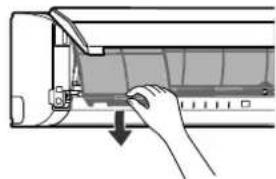
natural_image
Hand inserting a component into an air conditioner unit (no text or symbols visible)natural_image
Illustration of a hand inserting a component into an air conditioner unit (no text or symbols visible)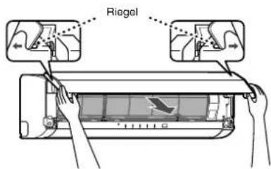
natural_image
Illustration of hands installing or adjusting a wall-mounted air conditioner (no text or symbols visible)SPEZIALWARTUNG
Reinigen des Plasmafilters
Vorbereitung:
natural_image
Illustration of a hand cleaning a corn cob in a rectangular basin with directional arrows (no text or symbols)VORSICHT
natural_image
Illustration of two children on a ladder, one holding a large cylindrical object (no text or symbols present)
natural_image
Cartoon illustration of a child reacting to a TV screen with a broken phone, no text or symbols present
FÖRSIKTIGHET
FÖRSIKTIGHET VID INSTALLATION
Inomhusenhet
NAMN OCH FUNKTIONER FÖR INOMHUSENHETENS INDIKATORER OCH KONTROLLER
Displaypanel

natural_image
Line drawing of a rectangular air conditioner housing (no text or symbols)
AUTOMATISK DRIFT
natural_image
Diagram showing airflow or fluid flow from a car air conditioner into a vehicle, with an inset illustrating the motion of airflow direction (no text or symbols present)AUTOMATISK ÅTERSTART
natural_image
Two-step illustration showing hands cleaning a grid surface with a tool (no text or symbols)
natural_image
Hand inserting a component into an air conditioner unit (no text or symbols visible)natural_image
Diagram of a hand inserting a component into an air conditioner unit (no text or symbols visible)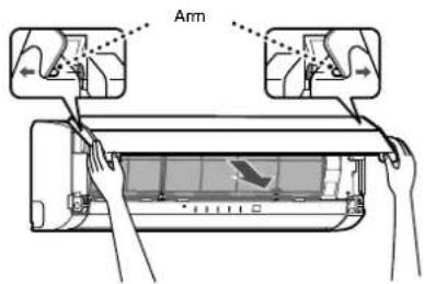
natural_image
Illustration of hands installing or adjusting a wall-mounted air conditioner (no text or symbols present)SPECIELLT UNDERHÅLL
natural_image
Illustration of a hand cleaning a woven mat in a rectangular basin with directional arrows (no text or symbols)FÖRSIKTIGHET
Plasmareningsfilter
LUFTKONDITIONERINGENS DRIFT OCH PRESTANDA
natural_image
Cartoon illustration of a man holding a remote, watching TV, and a dog reacting with surprise (no text or symbols)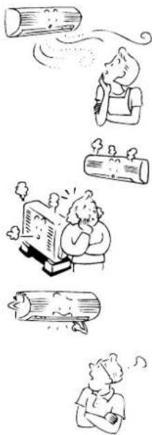
natural_image
Illustration of four different scenes: a person blowing a log, a person sleeping with steam, a person reading a book, and a person looking up with steam (no text or symbols present)SPECIFICATIONER
natural_image
Illustration of two children playing with a large book and a smiling face, one on a ladder and the other standing (no text or symbols)ПРЕДОСТРЕЖЕНИЕ

natural_image
Cartoon illustration of two children reacting to a large box on a TV (no text or symbols present)natural_image
Illustration of various household and outdoor activities including a computer, washing machine, cooking pot, and household items (no text or symbols)НАЗВАНИЯ ЧАСТЕЙ
Наружный блок
Батареи
natural_image
Line drawing of a double air conditioner unit (no text or symbols)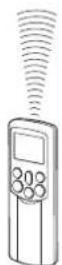
ОПЕРАЦИЯ 8°C
natural_image
Diagram of a car air conditioner unit with airflow direction indicator (no text or symbols)natural_image
Illustration of a hand pressing down on the back panel of an air conditioner (no text or symbols visible)
natural_image
Two-step illustration showing hands cleaning a grid surface with a tool (no text or symbols)RU
20


natural_image
Diagram of a hand inserting a component into an air conditioner unit (no text or symbols visible)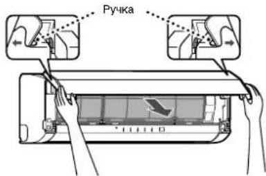
natural_image
Line drawing of hands installing or adjusting a wall-mounted air conditioner (no text or symbols)СПЕЦИАЛЬНЫЙ УХОД
natural_image
Illustration of a hand cleaning a woven bamboo mat in a rectangular basin (no text or symbols)ПРЕДУПРЕЖДЕНИЕ
natural_image
Illustration of a person blowing a cloud of smoke or vapor (no text or symbols)
natural_image
Illustration of two children on a ladder, one holding a smiling sign and the other kneeling (no text or symbols present)VAROITUS
ASENNUSTA KOSKEVIA VAROITUKSIA
natural_image
Cartoon illustration of two children reacting to a TV screen with a large explosion (no text or symbols)SIIRTÄMISTÄ JA KORJAAMISTA KOSKEVIA VAROITUKSIA
OSIEN NIMET
Ulkoyksikkö
Sisäyksikkö
SISÄYKSIKÖN OSOITTIMIEN JA SÄÄTIMIEN NIMET JA TOIMINNOT
Näyttöpaneeli
KAUKOSÄÄDIN JA SEN TOIMINNOT
Paristot
FI
6


natural_image
Line drawing of a cylindrical air conditioner unit (no text or symbols)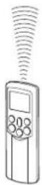
AUTOMAATTIKÄYTTÖ
AUTOMAATTIKÄYTTÖ (AUTOMAATTIVAIHTO)
KESKINOPEA + tai NOPEA .

JÄÄHDYTYS JA LÄMMITYS
Käynnistys
①-päinike
8 °C:n TOIMINTA
natural_image
Diagram showing airflow or fluid flow from a car air conditioner into a vehicle (no text or symbols)AUTOMAATTINEN UUDELLEENKÄYNNISTYS
natural_image
Hand inserting a component into an air conditioner unit (no text or symbols visible)Valmistelu:
natural_image
Two hand-drawn diagrams showing a pipe being cleaned on a grid surface, with no text or symbols present.FI
20


natural_image
Diagram of a hand inserting a component into an air conditioner unit (no text or symbols visible)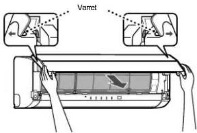

natural_image
Illustration of hands installing or adjusting a wall-mounted air conditioner (no text or symbols present)MUU KUNNOSSAPITO
natural_image
Illustration of a hand cleaning a woven mat in a rectangular basin with directional arrows (no text or symbols)HUOMIO
natural_image
Cartoon illustration of a person blowing a cup into a cylindrical container (no text or symbols)
natural_image
Illustration of two children on a ladder, one holding a smiling sign (no text or symbols present)ADVARSEL
INSTALLATIONSADVARSLER
natural_image
Cartoon illustration of two people reacting to a large screen showing a ringing phone (no text or symbols present)ADVARSLER VEDR∅RENDE FLYTNING OG REPARATION
DELENES NAVN
Udendørs enhed
Indendørs enhed
NAVNE OG FUNKTIONER PÅ DEN INDEND∅RS ENHEDS INDIKATORER OG BETJENINGER
Displaypanel
FORBEREDELSE OG KONTROL INDEN ANVENDELSE
DANSK
DN
Batterier
DN
6

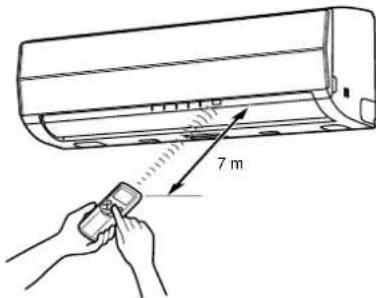
natural_image
Line drawing of a rectangular air conditioner unit (no text or symbols)
AUTOMATISK DRIFT
natural_image
Diagram showing airflow or fluid flow from a car air conditioner into a vehicle (no text or symbols)AUTOMATISK GENSTART
GODE RÅD TIL ∅KONOMISK DRIFT
natural_image
Hand inserting a component into an air conditioner unit (no text or symbols visible)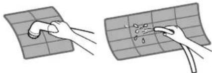
natural_image
Two-step illustration showing hands cleaning a grid surface with a tool (no text or symbols)DN
20

natural_image
Diagram of a hand inserting a component into an air conditioner unit (no text or symbols visible)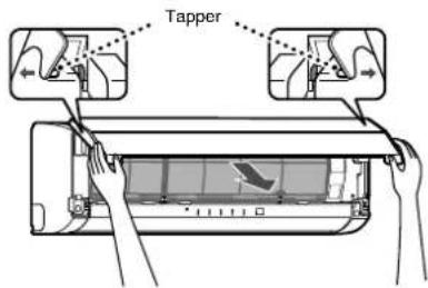
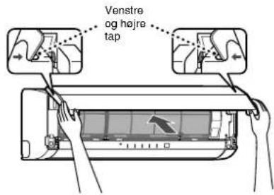
natural_image
Illustration of hands installing or adjusting a wall-mounted air conditioner (no text or symbols present)SÆRLIG VEDLIGEHOLDELSE
natural_image
Illustration of a hand using a tool to clean or wash a woven mat inside a rectangular basin (no text or symbols)FORSIGTIG
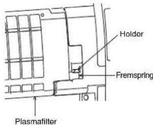
AIRCONDITIONANLÆGGETS DRIFT OG YDEEVNE
natural_image
Cartoon illustration showing a man watching a TV while a dog is sitting nearby (no text or symbols)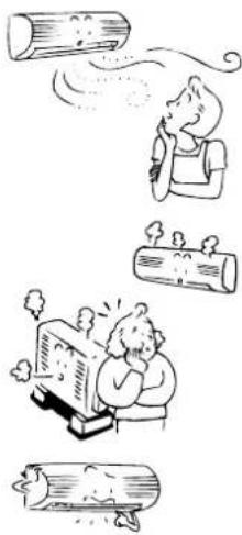
natural_image
Illustration of a person relaxing with steam from logs, another person smiling while holding a train, and two others looking up (no text or symbols)
SPECIFICATIONER
natural_image
Illustration of two children on a ladder, one holding a smiling sign and the other kneeling (no text or symbols present)ADVARSEL
INSTALLASJONSADVARSLER
- Husk å be en forhandler eller en elektroinstallatør om å installere klimaanlegget.
- Hvis klimaanlegget installeres på feil måte av deg selv, kan det forårsake visse problemer, som f.eks. vannlekkasjer, elektrisk støt, brann osv.
- Pass på at klimaanlegget alltid er jordet.
- Ikke koble jordledningen til gassrør, vannrør, lynavledere eller jordledninger for telefoner. Hvis klimaanlegget ikke er ordentlig jordet, kan det gi elektrisk støt.
FORSIKTIG
KOBLE APPARATET FRA STRÖMNETTET
natural_image
Cartoon illustration of a child reacting to a large screen showing a broken object, with another child observing (no text or symbols present)ADVARSLER SOM GJELDER FLYTTING OG REPARASJON
NAVN PÅ DELER
Utendørsenhet
Innendørsenhet
④Romtemperaturføler
⑤Frontpanel
⑥Luftinntaksgitter
⑦Luftfilter
⑧Luftutløp
⑨Lameller for horizontal luftstrøm
Plassert på baksiden av lamellen for den vertikale luftstrømmen.
⑩Lameller for vertikal luftstrøm
⑪Kontrollpanel
⑫Infrarød signalmottaker
⑬Fjernkontroll
⑭Plasmarensefilter
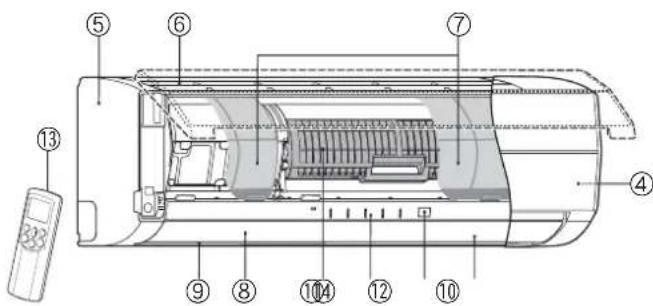
NAVN PÅ INDIKATORER OG KONTROLLER PÅ INNEND∅RSENHETEN, OG DERES FUNKSJONER
Kontrollpanel
Driftsmodusene er vist nedenfor.
①RESET-knapp
②FILTER-indikator (oransje)
③TIMER-indikator (gul)
④PURE-indikator (blå)
⑤OPERATION-indikator (driftsindikator) (grønn)
Driftsindikatorene blinker hurtig (5 ganger i sekundet) når en sikkerhetsfunksjon er aktivert.
⑥S.CLEAN-indikator (grønn)
⑤Viftehastighetsknapp (FAN)
⑨Timer AV-knapp (OFF)
⑱Timer AV-knapp (OFF)
⑧-indikator (minneindikator)
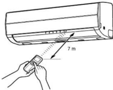

natural_image
Line drawing of a rectangular air conditioner housing (no text or symbols)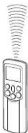
AUTOMATISK DRIFT
④Viftehastighetsknapp (FAN)
Velg en av innstillingene "AUTO" LAV-, LAV+, MED,
MED+ HOY
- - - - -
- OPERATION-indikatoren (grønn) på kontrollpanelet på innendørsenheten.
Driftsmodusen velges i samsvar med romtemperaturen, og driften starter etter ca. 3 minutter. - Temperaturen, viftehastigheten og lamellstillingen kan endres. Du kan velge de ønskede forholdene manuelt.
Stopp
-knappen
KJ∅LEDRIFT/OPPVARMINGSDRIFT
Start
①-kdappen
④Viftehastighetsknapp (FAN)
Velg en av innstillingene "AUTO" LAV-, LAV+, MED,
MED+ HOY

(Drift → Stopp → Drift)
MINNE/MIN KOMFORT-DRIFT
natural_image
Diagram showing airflow or cooling process of a car air conditioner with a magnified inset illustrating the motion direction (no text or symbols)NO
16


AUTOMATISK OMSTARTFUNKSJON (AUTOOMSTART)
natural_image
Cross-sectional diagram of a car air conditioner unit showing internal compartments and housing (no text or labels)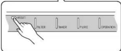
RESET-knapp
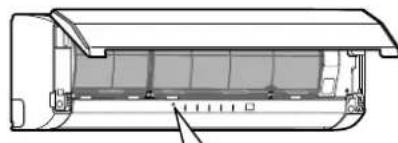
natural_image
Cross-sectional diagram of a mechanical component with internal layered structure (no text or symbols)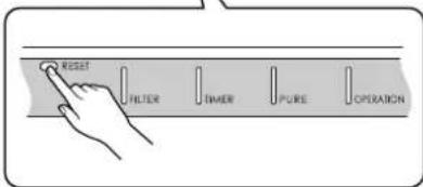
RESET-knapp
KLIMAANLEGGETS VIRKEMÅTE
Automatisk drift
Som vist på figur 1 velger Automatisk driftsmodus driftsmåten ut fra data om romtemperaturen (Ta) när anlegget startes.
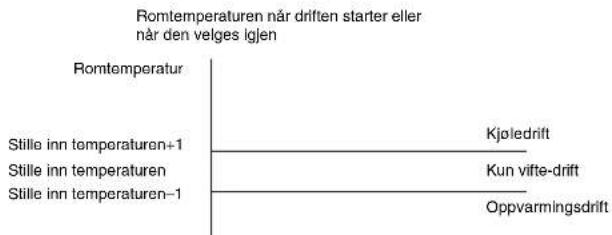
line
Romtemperaturen når driften starter eller når den velges igjen | Category | Value | | :--- | :--- | | Romtemperatur | | | Stille inn temperaturen+1 | Kjøledrift | | Stille inn temperaturen | Kun vifte-drift | | Stille inn temperaturen-1 | Oppvarmingsdrift |Figur 1
natural_image
Hand inserting a component into an air conditioner unit (no text or symbols visible)Forberedelser:
natural_image
Two hand-drawn diagrams showing a pipe being cleaned on a grid surface, with no text or symbols present.NO
20

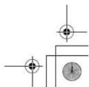
natural_image
Diagram of a hand inserting a component into an air conditioner unit (no text or symbols visible)
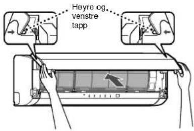
natural_image
Illustration of hands installing or adjusting a wall-mounted air conditioner (no text or symbols present)SPESIALVEDLIKEHOLD
natural_image
Illustration of a hand cleaning a woven mat in a rectangular basin with directional arrows (no text or symbols)FORSIKTIG
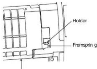
Plasmarensefilter
KLIMAANLEGGDRIFT OG -YTELSE
natural_image
Cartoon illustration of a person blowing a cup into a cylindrical container (no text or symbols)
RASseries_OwnersManual_BCV.fm Page 1 Wednesday, January 10, 2007 10:40 AM