RTIE3 - Thermostat STIEBEL ELTRON - Free user manual and instructions
Find the device manual for free RTIE3 STIEBEL ELTRON in PDF.

| Product type | Discharge regulator for storage heaters |
| Model | RTI-E3 (Stiebel Eltron) |
| Power supply | 230 V ~ 50 Hz, single-phase |
| Switching power | 10 A (max. 2300 VA) |
| Control function | Electronic 2-position (on/off) |
| Ambient temperature range | 5 to 35 °C (continuous adjustment via button R2) |
| Setpoint temperature in middle position | Approximately 20 °C |
| Temperature reduction (via external timer) | Approximately 4 K |
| Ambient temperature sensor | Integrated (B2), to be mounted on the back of the device |
| On/off switch | Present (S2), on control panel |
| Dimensions (approximate) | 80 × 80 × 30 mm (control module) |
| Weight (approximate) | 0.2 kg |
| Protection rating | IP20 (installation inside the heater) |
| Mounting | Inside the storage heater, by a qualified installer |
| Maintenance | Clean the exterior with a dry cloth; no user-serviceable parts |
| Safety | Comply with VDE 0100 standard; disconnect power before servicing |
| Spare parts | Potentiometer, switch, temperature sensor available from the manufacturer |
| Repairability | By a qualified installer; refer to the manual |
| Warranty | Valid in the country of purchase; contact the Stiebel Eltron subsidiary |
| Environment and recycling | Dispose of packaging according to national regulations; appliance recyclable |
Frequently Asked Questions - RTIE3 STIEBEL ELTRON
User questions about RTIE3 STIEBEL ELTRON
0 question about this device. Answer the ones you know or ask your own.
Ask a new question about this device
Download the instructions for your Thermostat in PDF format for free! Find your manual RTIE3 - STIEBEL ELTRON and take your electronic device back in hand. On this page are published all the documents necessary for the use of your device. RTIE3 by STIEBEL ELTRON.
USER MANUAL RTIE3 STIEBEL ELTRON
Discharge Control Module for Storage Heaters Operating and Installation Instructions
Français
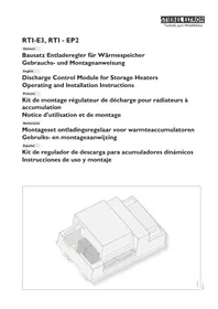
natural_image
Isometric technical drawing of a mechanical housing or enclosure with internal compartments and mounting brackets (no text or symbols)7975.01
240352
Inhaltsverzeichnis
Deutsch Seite
- Operating instructions 8
1.1 Mode of operation
- Installation instructions 8
2.1 Packing unit
2.2 Installation
2.3 Function test
2.4 Handover
-
Environment and recycling 10
-
Guarantee 10
Table des matières
Français page 11 - 13

1. Operating instructions for the user and the professional
RTI-E3
The RTI-E3 is an electronic 2-point control unit; i.e. the blower of the storage heater is switched on by the RTI-E3, operated at a constant speed, and then switched off again.
RTI-EP2
The RTI-EP2 is an electronic proportional control unit; i.e. the speed of the storage heater blower motor is steplessly adjusted by the RTI-EP2 to suit the heat requirement.
In this situation, the speed regulation of the blower motor is effected as a function of the difference between the room temperature (the actual temperature) and the temperature which has been set at the selector button R2 (the reference temperature). The smaller this difference, the lower the speed of the blower motor.
However, if the storage heater is being operated with a supplementary heating system, then the RTI-EP2 automatically switches over to a 2-point control arrangement; i.e. if heat is being given off, then the blower motors only run at full capacity. If the supplementary heating is switched off by means of the switch on the operating panel, then the RTI-EP2 again operates as a proportional control unit.
1.1 Mode of operation
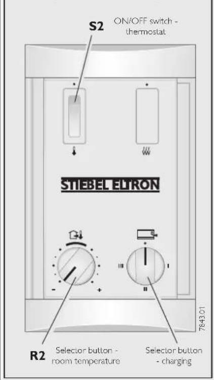
The discharge control unit is switched on and off by means of the S2 switch on the control panel of the storage heater (ON = "0").
The room temperature desired can be steplessly adjusted between about 5 to 35 °C by means of the R2 selector button on the operating panel. If the selector button is in the central position, the room temperature will be kept to a constant temperature of about 20 °C. If the room temperature drops below the preset value, the discharge control unit automatically switches on the storage heater blower motors, so that the stored heat is blown into the room.
After adjusting the temperature it may last y few minutes before the blower will start due to technical reasons.
On very cold days, it is recommended that the discharge control unit be switched on if no-one is going to be present for several days, in order to keep the room temperature at about 10 °C, for example, so as to prevent the building or the room from becoming too cold (to protect against freezing).
Night-time heating reduction
By utilising an external switch or timeclock, a temperature reduction of approx. 4 K can be achieved.
Briefly the most important

2. Installation instructions for the professional
The discharge control unit must be installed by an approved qualified installer, following these Operating and Installation Instructions as well as the instructions for the storage heater.
All electrical connection and installation work is to be carried out in accordance with VDE 0100 provisions, the regulations of the electricity supply utility companies concerned, and the corresponding national and regional regulations.
When connecting the storage heater to an automatic charging control device, it is possible, even with the fuses removed, that voltage will still be present at the terminals A1/Z1 - A2/Z2.
If several storage heaters are being set up next to one another, care is to be taken to ensure that the discharge control unit is installed in the right-hand outer device. This guarantees that the room temperature can be detected without any problem.
2.2.1 Installation sequence
→ Remove the air outlet and inlet grilles, the front wall, and the right side wall, as described in the installation instructions for the storage heater.
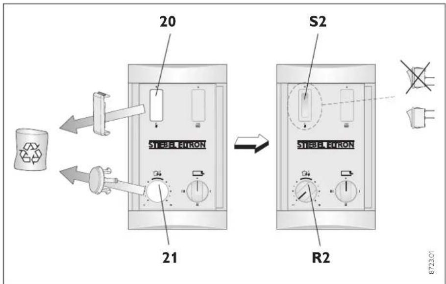
→ Push the blind cap for the switch (20) and temperature selector button (21) out of the operating panel from the switchbox side, using a mechanical aid.
⇒ Push the ON/OFF switch (S2) with the „flat plug upwards" into the operating panel from the front.
2.1 Packing unit
1 discharge control unit with
- connection lead for charge and discharge control unit
- 6-pin plug connector with cable harness
1 ON/OFF switch
1 adjuster (potentiometer) with connection lead
1 temperature selector button
1 set of operating and installation instructions
1 room temperature sensor with 2 screws
2 separate switch leads for switches
2.2 Installation
Before starting installation work, isolate the storage heater from the electricity supply.
flowchart
graph LR
    A["20"] --> B["STEEL-TRON"]
    B --> C["S2"]
    C --> D["R2"]
    D --> E["8723.0"]
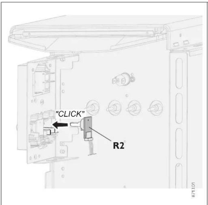
⇒ Push the temperature selector button (R2) into the operating panel and turn it as far as the left-hand stop.
Rotate the shaft of the potentiometer as far as the left-hand stop.
Engage the potentiometer into the operating panel from the switchbox side (check that the potentiometer shaft is properly located).
Lay the 3-pole connection lead of the potentiometer along behind the angle plate to the plug-in location of the discharge control unit (in this situation, fix the connection lead to the operating panel and the angle plate by means of the cable holder).
Pivot the angle plate located in the switchbox forwards in order to accommodate the mains connection terminals, after releasing (not unscrewing) the screw located in the rear wall.
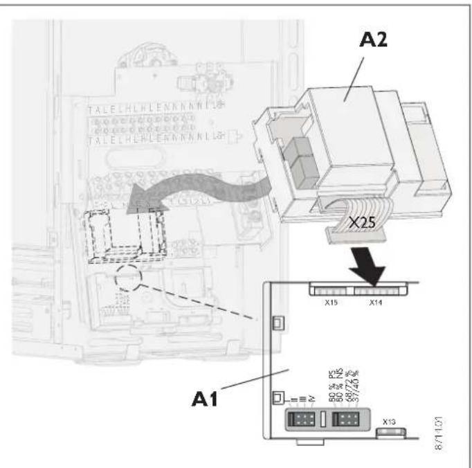
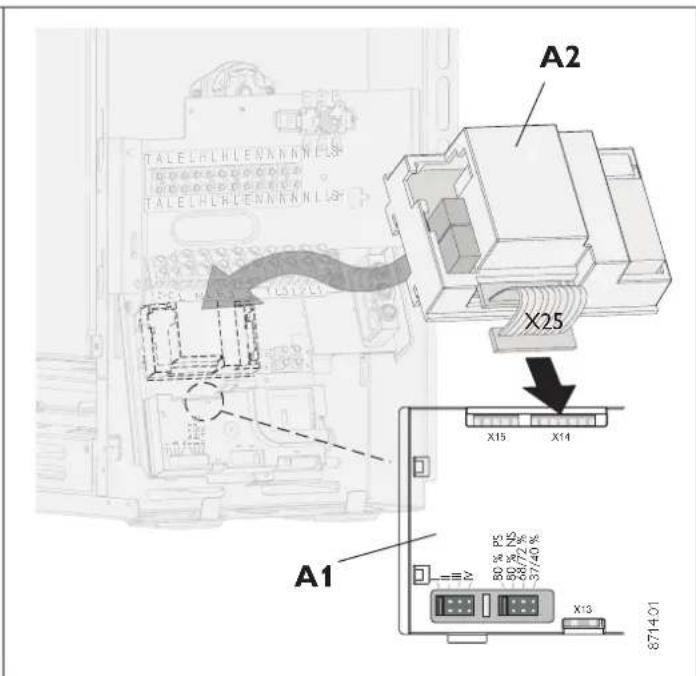
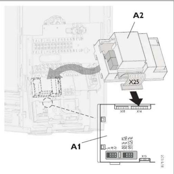
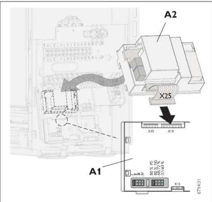
⇒ Plug the connection lead (X25) on the discharge control unit (A2) onto the charge control unit (A1).
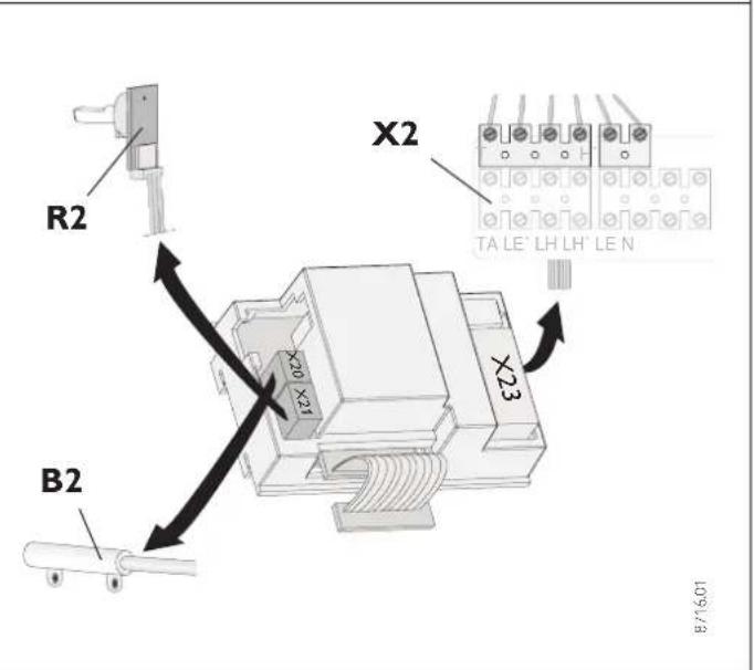
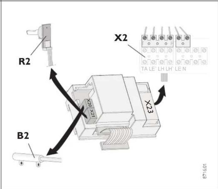
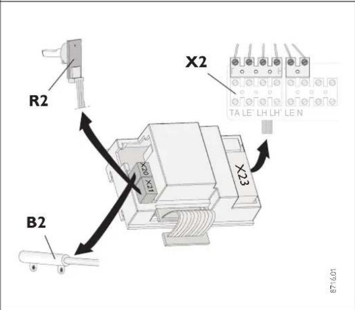
→ Guide the 6-pin plug connector of the discharge control unit along behind the angle plate and upwards, insert it form above into the plug-in locations „TA“ to „N“ of the connection terminal X2, and screw it tight (push the cable harness into the cable holder provided).
→ Plug the discharge control unit into the longitudinal holes located above the charge control unit and engage it in position.
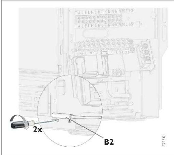
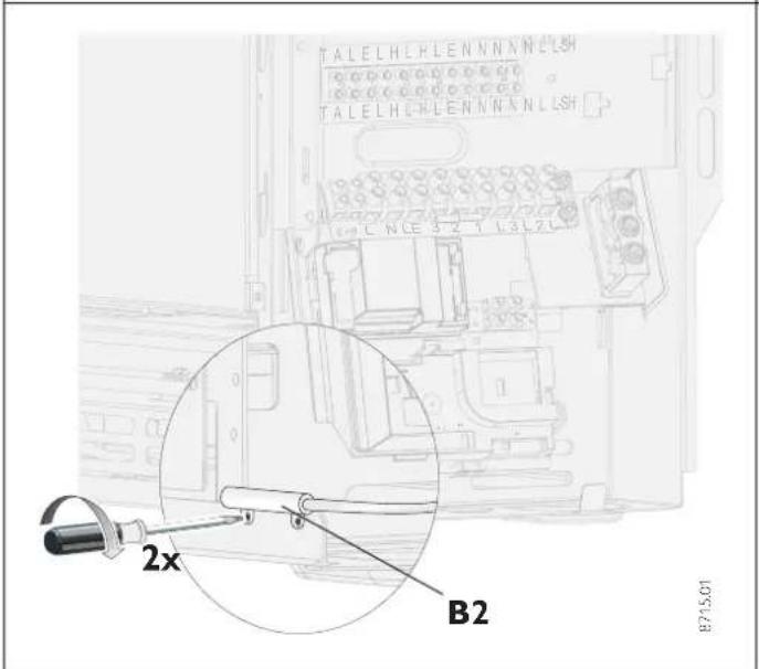
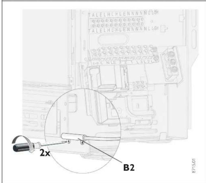
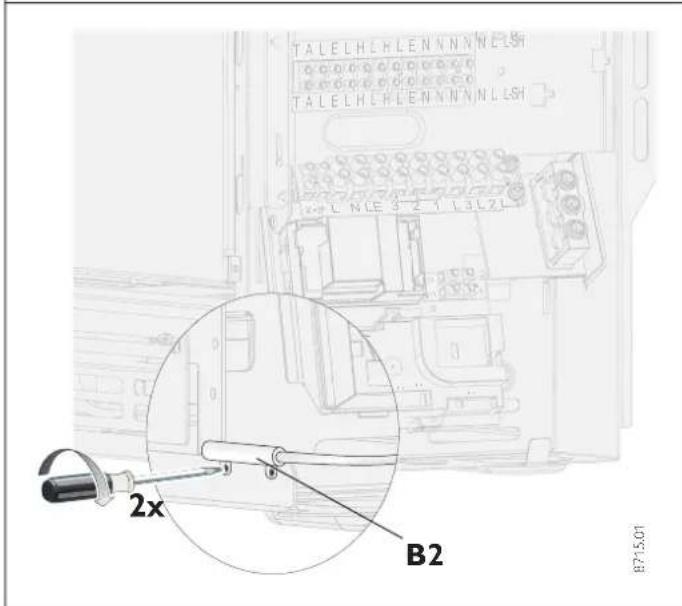
⇒ Screw the room temperature sensor (B2) with two screws (2.9 x 6.5) to the front inclined edge of the baseplate. Plug the connection cable into the plug-in location X20 of the discharge control unit.
⇒ Plug the connection lead of the potentiometer into the plug-in location X21 of the discharge control unit.
→ Guide the separate leads provided along behind the angle plate and connect them as shown in the following table (to the terminals X1 and X2 from below):
| Designation | Laying | |
| from | ||
| Lead (black) | L (X1) | S2 (top plug-in location) |
| Lead (brown) | LE'(X2) | S2 (bottom plug-in location) |
The leads must not come in contact with the operating panel conductor plate or simply insulated leads for safety extra-low voltage (SELV). Incorporate the leads to the S2 switch into the existing cable harness (drillers can be opened and then closed again).
⇒ Pivot the angle plate back to the rear again and screw it tight.
⇒ Secure the side wall, front wall, and air outlet and inlet grilles to the appliance once again (respect the installation sequence).
The toothed disks must be inserted beneath the securing screws of the side wall and the front wall (protective conductor connection).
The connection leads from the operating panel to the discharge control unit is to be laid and secured in the same way as the existing leads to the operating panel. They must not come in contact with the intermediate wall or the heating element connections.
2.2.2 Circuit diagram designations
X1 Mains connection terminal
X2 Connection terminal
Discharge control unit
A2 Electronic discharge control
B2 Room temperature sensor - discharge
R2 Adjuster - discharge
S2 ON/OFF switch, discharge control unit
X25 Internal connection strip A1-A2
2.2.3 Night time heating reduction - connection of an external time-clock
After installation, a switch or timeclock should be wired to terminals L and TA on terminal block X2. A temperature reduction of approximately 4 K can then be achieved.
The wiring for this modification must be provided by the installer; they are not included in the kit.
2.3 Function test
Set the ON/OFF switch to the position "0". Now rotate the temperature selector button until the blower of the storage heater switches on. If the blower does not switch on, the operating and fault displays on the charge and discharge control units are to be observed.
2.3.1 Operating and fault display on the electronic charging regulator
LED lights "green" ⇒ No fault
The charge control unit is working perfectly.
LED lights "red" ⇒ Fault
a) The selector button for charging (R1) and/or the core sensor (B1) is defective or not connected.
b) The plug bridge for reducing the degree of charge at the discharge control unit is missing.
No charging is taking place.
LED lights "orange" ⇒ Fault at the discharge control unit
a) Discharge control unit is defective.
b) Potentiometer for setting the discharge is defective and/or not connected.
The room temperature will be regulated to about 22 °C.
c) Room temperature sensor defective and/or not connected.
No discharge is taking place.
2.4 Handover
These Operating and Installation Instructions belong to the unit and are to be kept in a safe place by the owner: In the event of change of ownership, they are to be handed over to the new owner. In the event of any maintenance or repair work being necessary, the qualified installer is to be provided with the Operating and Installation Instructions in order to consult them.

3. Environment and recycling
Please help us to protect the environment by disposing of the packaging in accordance with the national regulations for waste processing.

4. Garantie
For guarantee please refer to the respective terms and conditions of supply for your country.

The installation, electrical connection and first operation of this appliance d be carried out by a qualified installer.
The company does not accept liability for failure of any goods supplied which are not installed in accordance with the manufacturer's instructions.


© 2-511 16111 Fax 2-35512122
E-Mail info@stiebel-eltron.cz
Internet www.stiebel-eltron.cz
France
Stiebel Eltron S.A.S.
469 Building 77, Bond Street
Tambon Bangpood
Ampur Pakkred
© 02-960 1602-4
Nonthaburi 11120
Fax 02-960 1605
Internet
stiebel@loxinfo.co.th
www.stiebeleltronasia.com
USA
Stiebel Eltron Inc.
242 Suffolk Street
©0413-538-7850
Holyoke MA 01040
Fax 0413-538-8555
Internet
info@stiebel-eltron-usa.com
www.stiebel-eltron-usa.com