
FEK - Thermostat STIEBEL ELTRON - Free user manual and instructions
Find the device manual for free FEK STIEBEL ELTRON in PDF.

| Product Type | Control module for weather-compensated heating/cooling systems |
| Brand | Stiebel Eltron |
| Model | FEK |
| Dimensions | 147 x 97 x 33 mm |
| Power Consumption | ~25 mA |
| Supply Voltage | 12 V DC ± 15% |
| Protection Class | II (EN 60730) |
| Ingress Protection | IP 40 (EN 60529) |
| Clock Backup | >10 hours |
| Operating Temperature | 0 to 50 °C |
| Storage Temperature | -20 to 60 °C |
| Room Temperature Sensor | NTC 5 kΩ, tolerance ±1% at 25 °C |
| Temperature Tolerance | ±0.2 K at 25 °C |
| Communication | BUS connection to WPMi control unit |
| Display | 12-digit plain text display |
| Controls | Rotary selector, Away key, Operating mode key, Help key, +, -, PRG, Reset |
| Adjustable Parameters | Room temperature, heating program, heating curve, system temperatures |
| Installation | Wall mounting on internal wall, avoid direct sunlight and drafts |
| Languages | Multiple languages selectable via menu |
| Access Level | User levels 1-2, contractor level 3 (code 1000) |
| Intended Use | For use with Stiebel Eltron WPMi for weather-compensated control |
Frequently Asked Questions - FEK STIEBEL ELTRON
User questions about FEK STIEBEL ELTRON
0 question about this device. Answer the ones you know or ask your own.
Ask a new question about this device
Download the instructions for your Thermostat in PDF format for free! Find your manual FEK - STIEBEL ELTRON and take your electronic device back in hand. On this page are published all the documents necessary for the use of your device. FEK by STIEBEL ELTRON.
USER MANUAL FEK STIEBEL ELTRON
Operating and installation instructions
natural_image
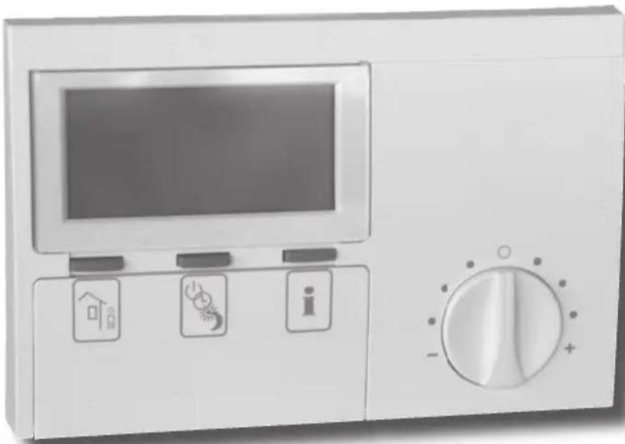
Illustration of a kitchen appliance with a digital display and three control buttons (home, alarm, info) on the front panel, with a rotary dial on the side (no text or symbols visible)26_03_01_0106
Index
1. Operating instructions 2
for users and contractors
1.1 Equipment description 2
1.2 Equipment overview 2
1.3 Important information 2
1.4 Operation 3
1.5 Settings 3
2. Installation instructions 12
for contractors
2.1 Standard delivery 12
2.2 General 12
2.3 Installation 12
2.4 Specification 13
2.5 Commissioning 13
1.1 Equipment description
The FEK control module only works in conjunction with the weather-compensated WPMi control unit. It enables the convenient entry and display of system parameters, e.g. outside temperature, relative humidity and heating circuit parameters (e.g. heating times and required room temperature) for the heating system from the user's living room. This allows the constant monitoring and optimising of the heating system, both in heating and in cooling mode. In addition, hooking up a room temperature enables the correction of the weather-compensated WPMi control unit.
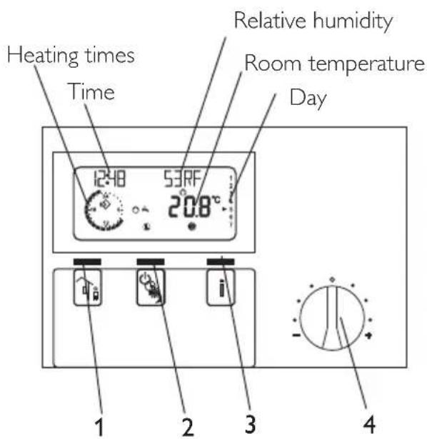
1.2 Equipment overview
1.2.1 With closed control flap and standard display
C26_21_01_0010
1 Away key
2 Operating mode key
3 Help key
4 Rotary selector for changing the set room temperature ± 5 K
1.2.2 With the control flap open and with all indicator elements on display
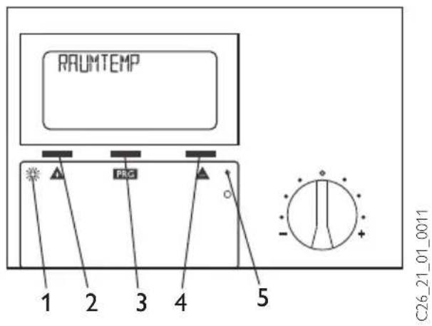
1 Programming indicator
2 + key
3 PRG key
4 - key
5 Reset
1.3 Important information

The control module must only be installed and maintained by qualified contractors.
1.4 Operation
The operation is split over three control levels. Control levels 1 and 2 are accessible to users and contractors alike. Control level 3 is only designed for qualified contractors:
Control level 1 (control flap closed)
This enables the adjustment of operating modes, such as standby mode, programmed operation, constant day or setback mode (for this, see section 1.5.1).
Control level 2 (control flap open)
This enables parameters, such as room temperature, heating programs, etc. to be adjusted (for this, see section 1.5.5).
Control level 3 (for contractors only) This level is protected by a code and should only be used by contractors. At this level, heat pump and system-specific details are determined (for this, see section 2.5).
Vital facts in brief
Settings
All adjustments follow the same pattern:
Opening the control flap toggles the FEK to control level 2. The display shows the parameter "room temp.".
Pressing ▲enables you to adjust the parameter you want to change.
Press PRG change the value of the parameter. You can change the currently displayed value with ▲ or ▼ when the red indicator is illuminated. Press PRG gain, the indicator then extinguishes and the new set value has been saved. You can modify further values for this parameter by pressing
▲ or ▼, if the red indicator has not been extinguished after saving.
The programming step can only be terminated when the red indicator has extinguished.
Terminating programming
You can terminate the programming process after entering and saving the required parameter changes by closing the control flap. However, if you want to make further changes, press one of the keys until the display shows BACK, then press PRG. This will return you to the previous level. Closing the control flap with illuminated indicator returns the FEK into its original position. The modified value will then not be saved.
1.5 Adjustments (control level 1)
With the flap closed, the display shows the operating mode, time and day, as well as the current room temperature and relative humidity.
1.5.1 Operating mode key

When connecting a FEK, only the operating modes for the pre-selected heating circuit are adopted by the WPMi.
You can select the required operating mode by pressing this key several times with the flap closed. The selected operating mode is indicated by a symbol in the display. It becomes effective if the setting was not changed for five seconds.
Standby mode
Frost protection for the heating operation is active. The standby symbol flashes, when the heat pump manager is in standby mode, and the operating mode cannot be adjusted.
Application: During holidays.
Automatic mode
eating according to time switch program.
Changeover between day temperature and setback temperature. With this operating mode, an additional symbol (sun or moon) indicates in the display, whether the heating circuit is currently in day or in setback mode.
constant day mode
The heating circuit is held at constant day temperature.
Application: In low energy houses without setback mode.
Constant setback mode
The heating circuit is held at constant setback temperature.
Application: During weekends away.
1.5.2 Away key

This key activates the eco mode (away).
Press twice: The heating circuit switches to setback mode for one hour. The selected heating interruption is briefly displayed in hours.
Press this key several times: the heating circuit switches for the respective number of hours to setback mode. If no key is then pressed for approx. three seconds, the display returns to the standard display and the active heating interruption is displayed by the flashing moon symbol.
You can scan the selected heating interruption by pressing the "Away" key once at any time. Pressing the operating mode key deactivates the "Away" period and the moon symbol will extinguish.
1.5.3 Help key

Pressing this key allows you to scan sensor temperatures of the heat pump or heat pump system, such as outside temperature, actual DHW temperature, actual return temperature, actual room temperature and the relative humidity.
After you press this key, the first display is the outside temperature. Continuing to press displays, in sequence, the actual DHW temperature, the actual return temperature, the maximum and minimum room temperatures and the maximum and minimum relative humidity. The standard display returns after five seconds.
The MIN/MAX values for room temperature and relative humidity are constantly updated and stored.
If you hold down the key for four seconds, the top of the display shows DELETE VALUES. All MIN/MAX values will then be deleted.
Any fault in the heat pump causes an arrow above the help key and the attention symbol to flash. Pressing the help key displays that fault. Three seconds later, the fault display extinguishes and the standard display returns again.
1.5.4 Room temperature
You can adjust the room temperature by +/- 5K with the rotary selector. This set value adjustment applies to the then current heating time, not to the setback time.
Display (including all elements)
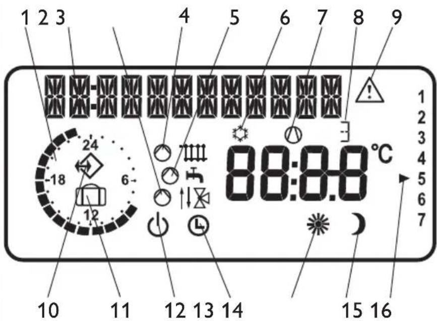
1 Heating times for central heating and DHW (black)
2 12-digit plain text display
3 Mixer mode
4 Heating mode
5 DHW mode
6 Cooling mode
7 Compressor runs
8 Booster in operation
Stage 1, 2 or 3
9 Fault message (flashing)
10 'BUS connection to the WPMi established
11 WPMI in away mode
12 Standby mode
13 Automatic mode
14 Constant day mode
15 Constant setback mode
16 Day
1.5.5 Overview of system parameter (control level 2)
Select the required parameter with the rotary selector.
For adjustments to parameters, turn to page 6.
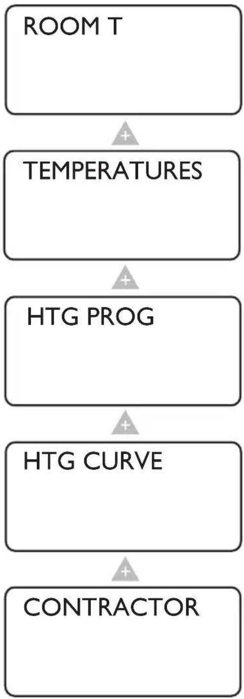
flowchart
graph TD
    A["ROOM T"] --> B["TEMPERATURES"]
    B --> C["HTG PROG"]
    C --> D["HTG CURVE"]
    D --> E["CONTRACTOR"]
With the Room temp. parameter you can adjust the set room temperature of the heating circuit for the day and setback mode.
The Temperatures parameter enables you to scan the sensor temperatures of the heat pump or heat pump system, comparing the actual with the set temperatures, the relative humidity, etc.
In the Heating program parameter, you can adjust the heating program.
In the Heating curve parameter, you can adjust the heating curve. The room temperature will only remain constant, irrespective of the outside temperature, if the correct heating curve has been selected for the relevant type of building. Selecting the correct heating curve is therefore vitally important.
During commissioning, you need to not only determine the settings of control level 2, but also the system-specific parameters. These parameters are adjusted at control level 3 by your heating contractor, access to which is protected by code.
Adjustments at control level 2 for users and contractors
The heating curve, room temperature and heating program parameters are not shown at the WPMi heat pump manager, if the FEK is pre-selected for a specific heating circuit.
Room temperature
With the Room temp. parameters you can adjust the set room temperature for the day and setback mode. Changing these parameters results in a parallel offset of the heating curve.
Open the control flap
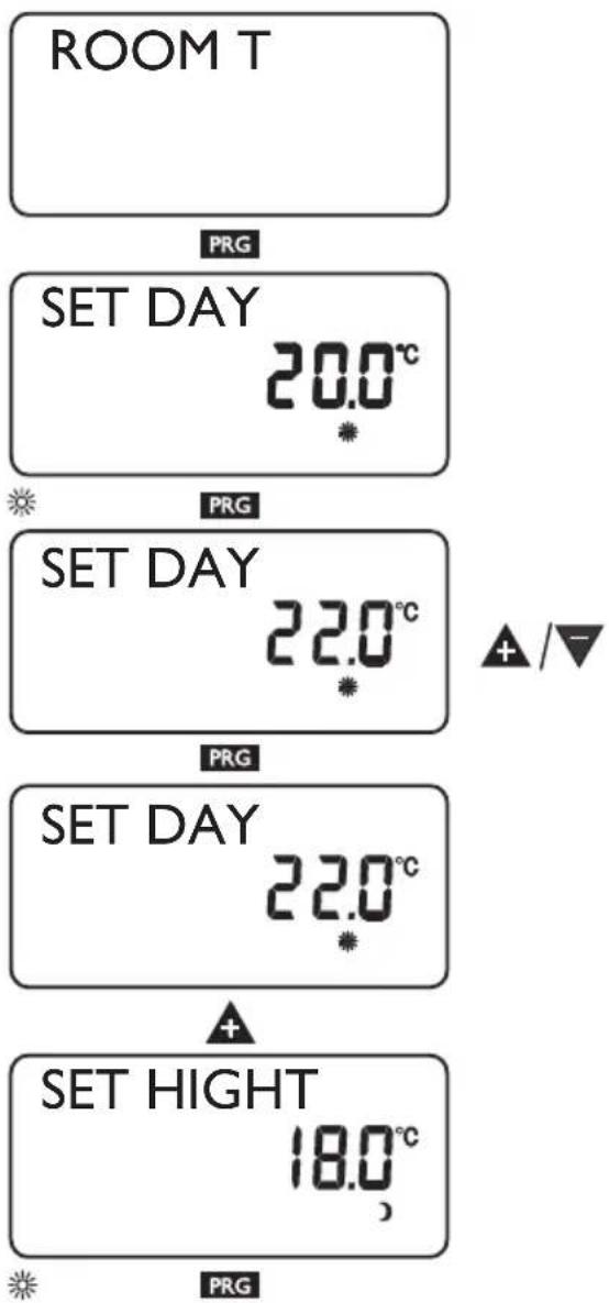
flowchart
graph TD
    A["SET HIGHT 20.0°C"] --> B["PRG"]
    B --> C["SET HIGHT 20.0°C"]
    C --> D["+"]
    D --> E["ROOM T 20.3°C"]
    E --> F["+"]
    F --> G["BACK"]
    G --> H["PRG"]
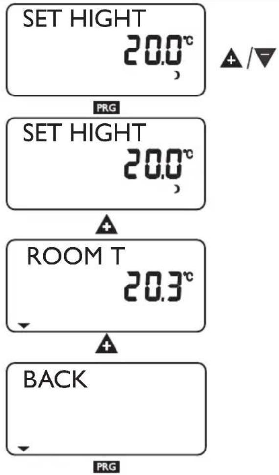
Temperatures
The Temperatures parameter enables you to scan the following sensor temperatures of the heat pump or heat pump system, comparing the actual with the set temperatures, the relative humidity, etc.
- Outside temperature
- Actual room temperature
- Set room temperature
- Relative humidity
- Actual DHW temperature
- Set DHW temperature
– Actual heat pump return temperature - System frost protection temperature
Note
No display, if the corresponding temperature sensor is not connected.
Open the control flap
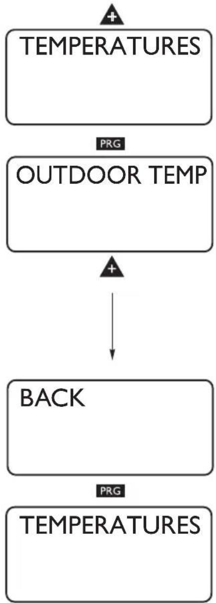
flowchart
graph TD
    A["TEMPERATURES"] --> B["OUTDOOR TEMP"]
    B --> C["BACK"]
    C --> D["TEMPERATURES"]
    style A fill:#f9f,stroke:#333
    style B fill:#f9f,stroke:#333
    style C fill:#ccf,stroke:#333
    style D fill:#ccf,stroke:#333
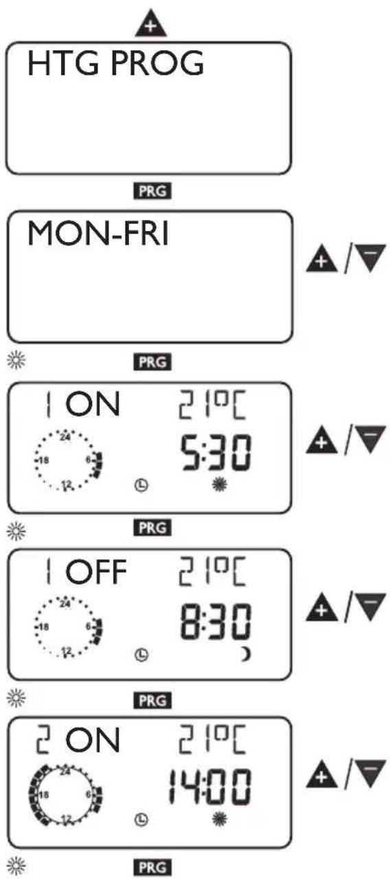
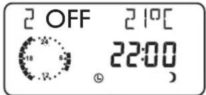
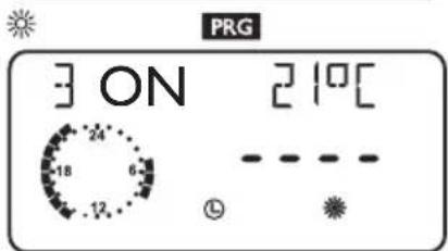
Heating program
Under this parameter you have the option of setting up a heating program, i.e:
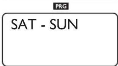
- for every day of the week (Mo, ..., Su)
- Monday to Friday (Mo - Fr)
– Saturday and Sunday (Sa - Su) - the whole week (Mo - Su)
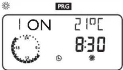
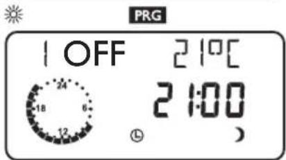
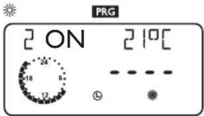
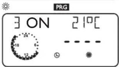
You can adjust three switching time pairs (I, II, III) for each of these options. This determines when and how often the heat pump system should heat in day mode.
At all other times, the heat pump operates in setback mode. You will already have selected the corresponding set values for day and setback mode under the Room temp. parameter.
Example:
Your heating system should operate daily from Monday to Friday at two different times, i.e. from 05:30 h until 08:30 h and from 14:00 h until 22:00 h. For the weekend, your heating system should provide heat from 08:30 h until 21:00 h.
Open the control flap


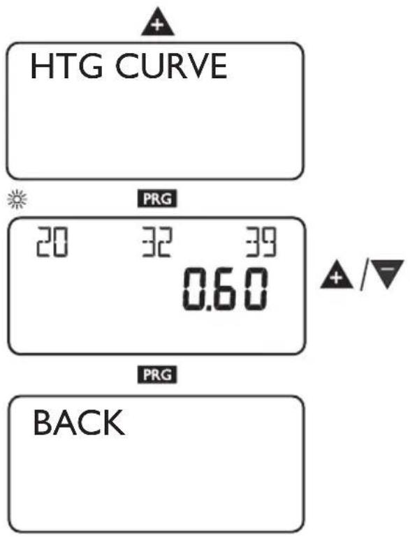
Heating curve
The Heating curve parameter allows you to select a heating curve for heating circuit 1 or 2. Selecting the correct heating curve is vitally important.
Note: Your contractor will have set up a building and system-specific optimum heating curve for the heating circuit. It relates to the heat pump return temperature for heating circuit 1 and to the mixer flow temperature for heating circuit 2.
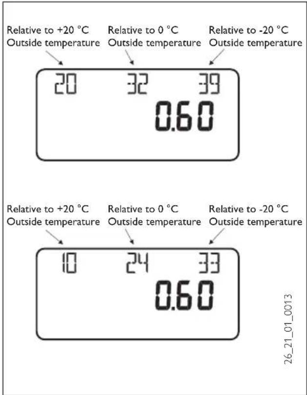
When adjusting the heating curve, the calculated set return or flow temperature, which is subject to the outside temperature and the set room temperature, will be shown at the top of the display.
Open the control flap
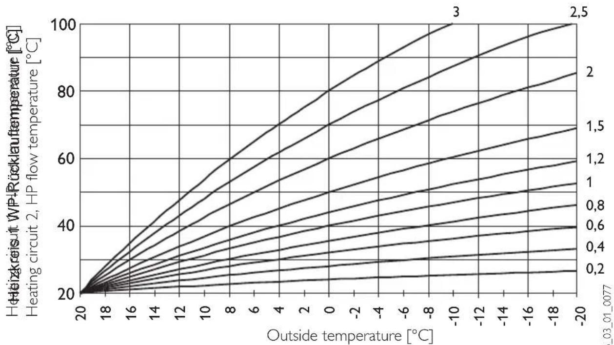
Heating curve diagram
One heating curve respectively can be adjusted for heating circuit 1 and heating circuit 2. At the factory, heating curve 0.6 is set up for heating circuit 1 and heating curve 0.2 for heating circuit 2. These heating curves relate to a set room temperature of 20 °C .
line
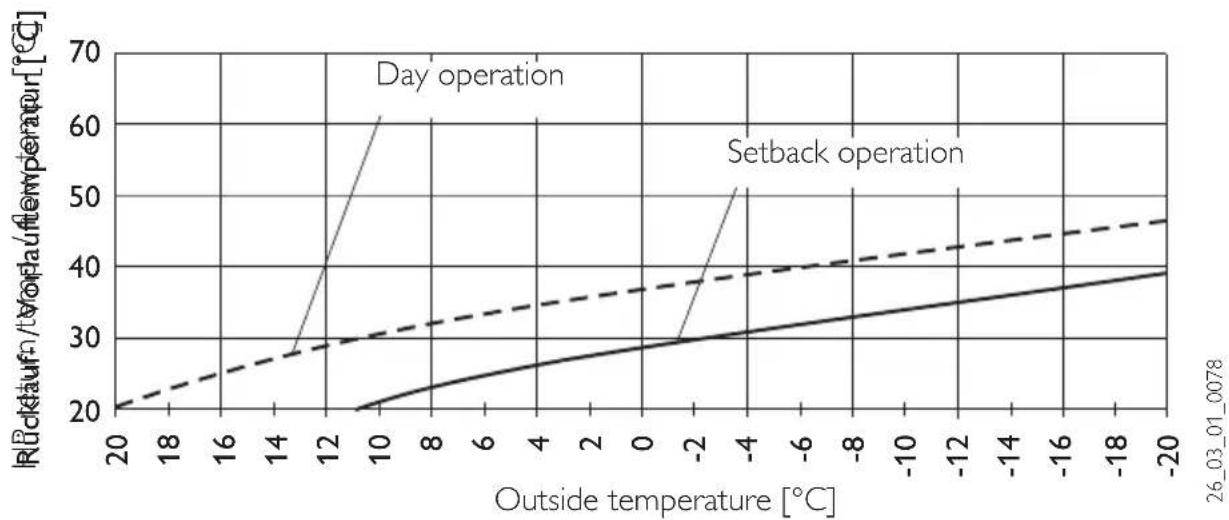
| Outside temperature [°C] | Heizakreisit WP+Rücklau temperature [°C] (1) | Heizakreisit WP+Rücklau temperature [°C] (2) | Heizakreisit WP+Rücklau temperature [°C] (3) | Heating circuit 2, HP flow temperature [°C] (1) | Heating circuit 2, HP flow temperature [°C] (2) | Heating circuit 2, HP flow temperature [°C] (3) | | ------------------------- | --------------------------------------------- | --------------------------------------------- | --------------------------------------------- | -------------------------------------------- | -------------------------------------------- | -------------------------------------------- | | 20 | 20 | 20 | 20 | 20 | 20 | 20 | | 18 | 25 | 26 | 27 | 24 | 25 | 26 | | 16 | 30 | 32 | 34 | 28 | 30 | 32 | | 14 | 35 | 38 | 41 | 32 | 34 | 36 | | 12 | 40 | 44 | 48 | 36 | 38 | 40 | | 10 | 45 | 50 | 55 | 40 | 42 | 44 | | 8 | 50 | 56 | 61 | 44 | 46 | 48 | | 6 | 55 | 62 | 67 | 48 | 50 | 52 | | 4 | 60 | 68 | 73 | 52 | 54 | 56 | | 2 | 65 | 74 | 80 | 56 | 58 | 60 | | 0 | 70 | 80 | 86 | 60 | 62 | 64 | | -2 | 75 | 86 | 92 | 64 | 66 | 68 | | -4 | 80 | 92 | 98 | 68 | 70 | 72 | | -6 | 85 | 98 | 104 | 72 | 74 | 76 | | -8 | 90 | 104 | 110 | 76 | 78 | 80 | | -10 | 95 | 110 | 116 | 80 | 82 | 84 | | -12 | 100 | 116 | 122 | 84 | 86 | 88 | | -14 | | | | | | | | -16 | | | | | | | | -18 | | | | | | | | -20 | | | | | | | S_03_01_0077Adjustment of programmed changeover between day/setback mode
The figure shows a standard heating curve with a slope of 0.8, relative to a set room temperature for day mode of 20 °C. The lower curve represents the setback curve. For this, a set room temperature for setback mode of 15 °C is used, in other words the heating curve is subjected to a parallel offset.
line
| Outside temperature [°C] | Rückkauf/VOF temperature [°C] (Day operation) | Rückkauf/VOF temperature [°C] (Setback operation) | | ------------------------ | --------------------------------------------- | ------------------------------------------------- | | 20 | 20 | 20 | | 18 | 22 | 22 | | 16 | 24 | 24 | | 14 | 26 | 26 | | 12 | 30 | 28 | | 10 | 40 | 30 | | 8 | 60 | 32 | | 6 | 60 | 34 | | 4 | 60 | 36 | | 2 | 60 | 38 | | 0 | 60 | 40 | | -2 | 60 | 42 | | -4 | 60 | 44 | | -6 | 60 | 46 | | -8 | 60 | 48 | | -10 | 60 | 50 | | -12 | 60 | 52 | | -14 | 60 | 54 | | -16 | 60 | 56 | | -18 | 60 | 58 | | -20 | 60 | 60 |Matching a heating curve to actual conditions
Example: During spring and autumn, the return or flow temperature of a heating system is too low at an outside temperature between 5 and 15 °C, but is OK at outside temperatures of ≤ 0 °C. This problem can be remedied by a parallel offset and a simultaneous reduction of the heating curve. Prior to this adjustment, heating curve 1.0 was adjusted, relative to a set room temperature of 20 °C. The dotted line indicates the modified heating curve at 0.83 and a modified set room temperature at 23.2 °C.
HP return temp. / flow temp. [°C]
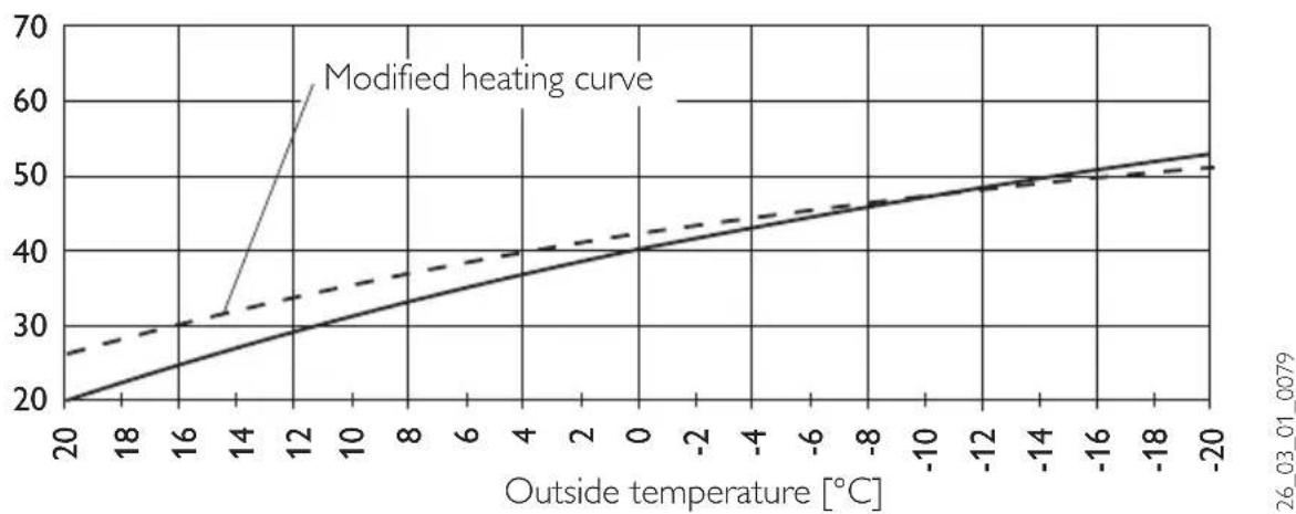
line
| Outside temperature [°C] | Modified heating curve | | ------------------------ | ---------------------- | | 20 | 20 | | 18 | 25 | | 16 | 30 | | 14 | 35 | | 12 | 40 | | 10 | 45 | | 8 | 50 | | 6 | 55 | | 4 | 60 | | 2 | 65 | | 0 | 70 | | -2 | 75 | | -4 | 80 | | -6 | 85 | | -8 | 90 | | -10 | 95 | | -12 | 100 | | -14 | 105 | | -16 | 110 | | -18 | 115 | | -20 | 120 |2 Installation instructions for contractors
2.1 Standard delivery
FEK Part no: 22 01 93
Dimensions: 147 × 97 × 33 (mm)
2.2 General information
The FEK is vitally important for area cooling, e.g. underfloor heating systems, area heating etc. Apart from the room temperature, it also determines the relative humidity to prevent condensation.
2.3 Installation
The correct function of the control module can only be assured if the following are observed:
- Fitting on an internal wall (not in a recess)
- No cover through curtains or similar
- External heat influence is prevented (e.g. sun, heating system, TV set)
– Prevention of direct draughts (next to windows and doors)
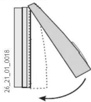
For fitting, remove the top part of the casing by levering a screwdriver above the opening in the bottom part.
Secure the bottom part on the wall and connect the BUS cable.
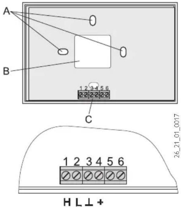
A Fixing holes
B Cable entry (knock-out)
C Terminals
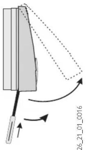
Position the top part of the casing centrally at the upper edge, hook into place and then pivot down onto the base, using only light pressure, and push home.
2.4 Specification
| Supply voltage 12 V DC ± 15 % | |
| Power consumption | ~ 25 mA |
| EN 60529 IP 40 | |
| EN 60730 Protection class II | |
| Clock backup > 10 hours | |
| Permiss. ambient temp. during operation | 0 to 50 °C |
| Permiss. ambient temp. during storage | - 20 to 60 °C |
| Room temperature sensor resistance | Test resistance NTC 5 kΩ |
| Tolerance in Ohm | ± 1 % at 25 °C |
| Temperature tolerance | ± 0.2 K at 25 °C |
2.5 FEK commissioning
Only approved contractors may commission this control module and instruct the owner in its use.
Not only the adjustments at control level 2 but also the system-specific parameters must be determined as part of commissioning the FEK. These parameters are adjusted at control level 3, access to which is protected by code. To reach this point, press▲, until you reach the "Contractor" parameter, then press PR.G neck all parameters in sequence,
Note: Not all adjustments take immediate effect. Some adjustments only become effective in certain situations or after a delay.
Code 1000
Enter the correct four-digit code to change parameters at control level 3.
The factory-set code is 1 0 0 0.
After pressing PKG (Indicator illuminates), by pressing + you can adjust the first digit.
Pressing PRC again confirms the value, then the second digit of the code begins to flash.
Pressing ▲enables the adjustment of the second digit of the code, etc. The display shows CODE OK when all four digits have been entered correctly. This enables access to control level 3. Closing and re-opening the flap requires that the code is entered again. Checking settings does not require the code to be entered.
Language
Press PRG and select the required language with ▲Then confirm your selection by pressing PRG.
Contrast
Press PRG and adjust the contrast with + or ▼
SELECT REM CON
You can predetermine with parameter FE selection, to which heating circuit the remote control applies.
As standard, HC1 is pre-selected. Accordingly, the parameters room temp., heating curve and heating program for heating circuit 1 are not displayed at the WPMi.
FE Correction
This parameter enables the calibration of the actual room temperature.
Room influence for FEK
Standard setting 5; adjustable from ----via "0 to 20" dashes (----) in the display:
When the FEK control module is connected, the room temperature sensor only serves to capture and display the actual room temperature; it has no influence on the actual control. With any setting, you can adjust the set room temperature for the heating circuit at the FEK control module by ±5 K. This set value adjustment applies for the then current heating time, not for the setback time.
At the same time, setting “0 to 20” serves to control the room temperature-dependent night setback. This means, the heating circuit pump is switched OFF at the point of changeover from the heating into the setback phase. It remains OFF, until the actual room temperature first drops below the set room temperature. Afterwards the system regulates in weather-compensated mode.
If you want the room temperature to be taken into account, set the room temperature sensor influence to > 0. The room sensor influence has the same effect as the outside temperature sensor has on the return temperature. Only this effect is 1 to 20 times greater than the set factor.
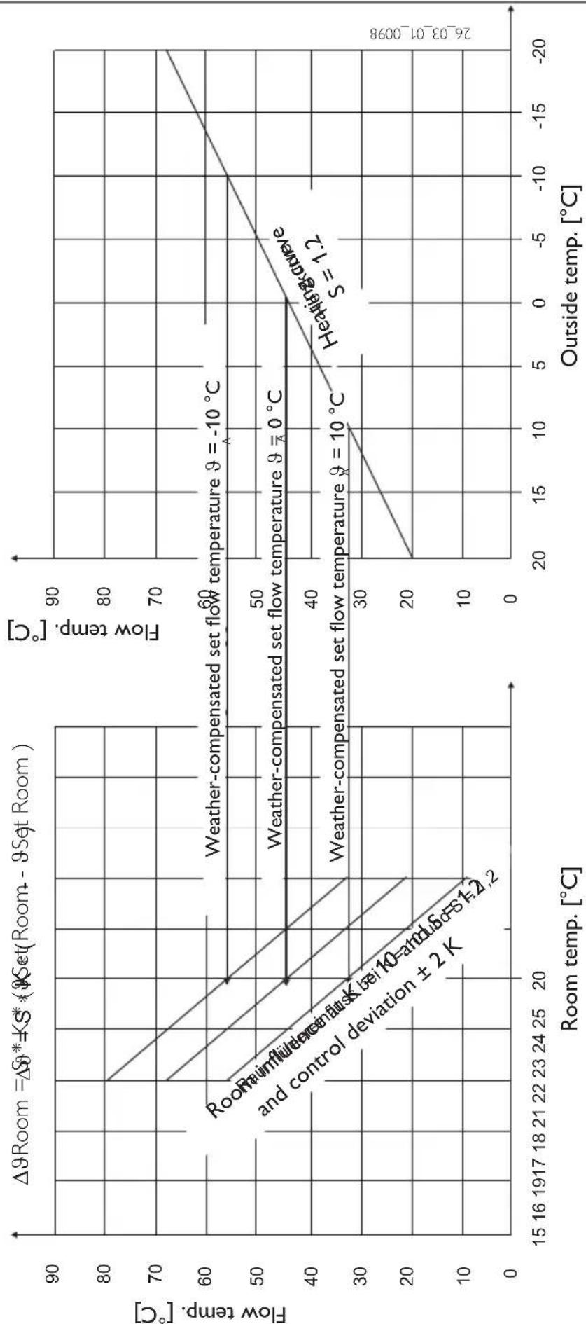
Room temperature-dependent return temperature with weather compensation
With this type of control, a control cascade is formed from weather-compensated and room temperature-dependent return temperature control. In other words, the weather-compensated return temperature control pre-selects the return temperature, which is corrected by the overlaid return temperature control in accordance with the following formula:
$$ \Delta \vartheta_ {R} = (\vartheta_ {R s e t} - \vartheta_ {R a c t u a l}) * S * K $$
Because a substantial proportion of control is already taken care of by the weather-compensated control, the room temperature sensor influence K can be set lower than with a purely room temperature control (K = 20). The figure on page 15 indicates the control method with the set factor K = 10 (room influence) and a heating curve S = 1.2.
Room temperature control with weather-compensation
This type of control offers two substantial benefits:
Incorrectly set heating curves are corrected by the room temperature sensor influence K, whilst the smaller factor K provides more stable control.
However, observe the following for all control units with room temperature sensor influence:
- The room temperature sensor must capture the room temperature accurately.
- Open doors and windows severely influence the control result.
- All radiator valves in the lead room must always be fully open.
- The temperature inside the lead room is decisive for the entire heating circuit.
Set the room temperature sensor influence to > 0, if you want the room temperature to be taken into account.
LCD test
Pressing PPG once initiates a LCD test. All display elements are displayed in sequence.
FEK software
Display of the current software issue.
Room influence
line
| Room temp. [°C] | Flow temp. [°C] | | --------------- | --------------- | | 20 | 45 | | 23 | 55 | | 26 | 60 |www.stiebel-eltron.com
Exclusive Distributor:
Applied Energy Products Ltd.
Morley Way GB-Peterborough PE2 9JJ
① 08709 000420 Fax 01733-319610
E-Mail sales@applied-energy.com
Internet www.applied-energy.com
Magyarország
Stiebel Eltron Kft.
Pacsirtamezó' u. 41 H-1036 Budapest
① 012 50-6055 Fax 013 68-8097
E-Mail info@stiebel-eltron.hu
Internet www.stiebel-eltron.hu
Nederland
17 West Street West Hatfield MA 01088
① 04 13-247-3380 Fax 0413-247-3369
E-Mail info@stiebel-eltron-usa.com
Internet www.stiebel-eltron-usa.com
Irrtum und technische Änderungen vorbehalten · Subject to errors and technical changes! · Sous réserve d'erreurs et de modifications techniques! · Onder voorbehoud van vergissingen en technische wijzigingen! · Salvo error o modificación técnica! · Rätt till misstag och tekniska ändringar förbehålls! · Excepto erro ou alteração técnica · Zastrzeżone zmiany techniczne i ewentualne błędy · Omyly a technické změny jsou vyhrazeny! A muszaki változtatások és tévedések jogát fenntartjuk! Возможность неточностей и технических изменений не исключается


- Operating and installation instructions
- Index
- Operating instructions 2
- Installation instructions 12
- Equipment description
- Equipment overview
- Important information
- Operation
- Control level 1 (control flap closed)
- Control level 2 (control flap open)
- Vital facts in brief
- Settings
- Terminating programming
- Adjustments (control level 1)
- Operating mode key
- Standby mode
- Automatic mode
- constant day mode
- Constant setback mode
- Away key
- Help key
- Room temperature
- Overview of system parameter (control level 2)
- Adjustments at control level 2 for users and contractors
- Room temperature
- Temperatures
- Note
- Heating program
- Example:
- Heating curve
- Heating curve diagram
- Adjustment of programmed changeover between day/setback mode
- Matching a heating curve to actual conditions
- Installation instructions for contractors
- Standard delivery
- General information
- Installation
- Specification
- FEK commissioning
- Code 1000
- Language
- Contrast
- SELECT REM CON
- FE Correction
- Room influence for FEK
- Room temperature-dependent return temperature with weather compensation
- Room temperature control with weather-compensation
- LCD test
- FEK software
- www.stiebel-eltron.com
- Magyarország
- Nederland
Brand : STIEBEL ELTRON
Model : FEK
Category : Thermostat