PRO 900 IX - Basket BORETTI - Free user manual and instructions
Find the device manual for free PRO 900 IX BORETTI in PDF.
| Product type | Kitchen hood |
| Brand | Boretti |
| Model | PRO 900 IX |
| Width | 900 mm |
| Electrical supply | 220-240 V single phase, 50 Hz / 220 V, 60 Hz, Class I |
| Recommended installation height | 65 to 70 cm above the cooking surface |
| Outlet diameter | Conforms to the appliance diameter, do not connect to a ventilation system |
| Motor speeds | 3 speeds + timed intensive speed (10 min) |
| Lighting | On/off control by remote control, standard bulbs (do not exceed the prescribed power) |
| Metal filters | Dishwasher safe, clean every 2 months (normal use) |
| Charcoal filters (recirculation option) | Removable, replace after 200 hours of operation |
| Filter saturation indicator | LED F flashes at 100h for metal, LEDs F+C at 200h for charcoal |
| Extraction mode | Outside or recirculation (configurable by + button) |
| Remote control | Included, alkaline batteries LR03-AAA 1.5V |
| Cleaning the body | Non-abrasive detergent, slightly damp sponge |
| Maintenance of the exhaust duct | Check every 6 months |
| Safety | Minimum distance of 65 cm from cooking surface; do not flambé under the hood; turn off motor before maintenance |
| Standards | IEC 335, low voltage directive 73/23 and EMC 89/336 |
| Warranty | Contractual, does not cover consumables (bulbs, filters) |
| Spare parts | Use exclusively original parts, order with appliance serial number |
| Recycling | Complies with WEEE directive 2002/96/EC, do not dispose with household waste |
Frequently Asked Questions - PRO 900 IX BORETTI
User questions about PRO 900 IX BORETTI
0 question about this device. Answer the ones you know or ask your own.
Ask a new question about this device
Download the instructions for your Basket in PDF format for free! Find your manual PRO 900 IX - BORETTI and take your electronic device back in hand. On this page are published all the documents necessary for the use of your device. PRO 900 IX by BORETTI.
USER MANUAL PRO 900 IX BORETTI
natural_image
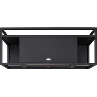
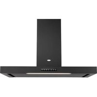
Exterior view of a stainless steel kitchen range hood with ventilation grilles and ventilation duct (no text or symbols visible)PRO 1000 IX & 900IX
NOTICE D'INSTALLATION ET D'UTILISATION INSTRUCTIONS FOR INSTALLATION AND DIRECTIONS FOR USE MONTAGE- UND GEBRAUCHSANWEISUNG LIBRETTO DI ISTRUZIONI INSTRUCCIONES DE INSTALACION E UTILIZACION MONTAGE- EN GEBRUIKSHANDLEIDING
F SOMMAIRE 1
RACCORDEMENT ÉLECTRIQUE
CONSEILS D'INSTALLATIONS
POSE DE L'APPAREIL
FONCTIONNEMENT
CONSEILS D'UTILISATIONS
ENTRETIEN
GARANTIE ET SERVICE APRÈS-VENTE
REMARQUES
GB CONTENTS 5
ELECTRICAL WIRING
INSTALLATION ADVICE
FITTING THE APPLIANCE
OPERATION
USEFUL HINTS
MAINTENANCE
GUARANTEE AND AFTER-SALES-SERVICES
REMARKS
D INHALT 10
NETZANSCHLUSS
MONTAGEHILFEN
MONTAGE DES GERÄTES
BETRIEB DES GERÄTES
NUTZUNG
Thank you for buying a BORETTI product which has been manufactured to the highest quality standards to meet your requirements.
We recommend you carefully read this booklet in which you will find instructions for installation, hints for use and maintenance.
1 ELECTRICAL
- This cooker hood is fitted with a 3-core mains cable with a standard 10/16A earthed plug.
• Alternatively the hood can be connected to the mains supply via a double-pole switch having 3mm minimum contact gap on each pole. - Before connecting to the mains supply ensure that the mains voltage corresponds to the voltage on the rating plate inside the cooker hood.
- Technical Specification: Voltage 220-240, single phase \~50Hz / 220 V - 60 Hz.
2 INSTALLATION ADVICE
- Ensure the cooker hood is fitted in compliance with the recommended fixing heights.
- To ensure the safe operation of this cooker hood, we recommend that the hood should not be fitted below 65cm (for electric) or (70cm for gas) the measurements taken from the surface of the cooking appliance to the underside of the cooker hood.
- It is a possible fire risk if the hood is not sited as recommended.
• To ensure the best results, the cooking fumes should be able to rise naturally towards the inlet grilles on the underside of the cooker hood and the cooker hood should be positioned away from doors and windows, which will create turbulence. - Ducting
- If the room where the hood is to be used contains a fuel-burning appliance such as a central heating boiler then its flue must be of the room sealed or balanced flue type.
- If other types of flue or appliances are fitted ensure that there is an adequate supply of fresh air to the room. Ensure the kitchen is fitted with an airbrick, which should have a cross-sectional measurement equivalent to the diameter of the ducting being fitted, if not larger.
- The ducting system for this cooker hood must not be connected to any existing ventilation system, which is being used for any other purposes or to a mechanically controlled ventilation ducting.
- The ducting used must be made from fire retardant materials and the correct diameter must be used, as incorrect sized ducting will affect the performance of this cooker hood.
- When the cooker hood is used in conjunction with other appliances supplied with energy other than electricity, the negative pressure in the room must not exceed 0.04 mbar to prevent the fumes from combustion being drawn back into the room.
- The appliance is for domestic use only and should not be operated by children or people who are infirm without supervision.
- This appliance must be positioned so that the wall socket is accessible.
3 FITTING
Any permanent electrical installation must comply with the latest regulations concerning this type of installation and a qualified electrician must carry out the work. Non-compliance could cause serious accidents or injury and would deem the manufacturers guarantee null and void.
IMPORTANT - The wires in this mains lead are coloured in accordance with the following code :
green / yellow : earth blue : neutral brown : live
As the colours of the wires in the mains lead of this appliance may not correspond with the coloured markings identifying the terminals in your plug, proceed as follows.
- The wire which is coloured green and yellow must be connected to the terminal in the plug which is marked with the letter E or by the earth symbol 12 or coloured green or green and yellow.
- The wire which is coloured blue must be connected to the terminal which is marked with the letter N or coloured black.
- The wire which is coloured brown must be connected to the terminal which is marked with the letter L or coloured red.
1) Draw a vertical line up the wall from the centre of the cooking appliance below as illustrated in fig. 4 - item 1.
2) Mark a point on the vertical line which corresponds to the lower canopy position (The height H of the splashback item B is 450 mm) and draw a horizontal line parallel to the stove top at a distance of 580 - 18 mm above this point.
3) Mark the 2 hole centres for the canopy fixing cup screws item T at a distance both left and right of the vertical line of 312 mm as illustrated in fig. 4.
4) Place one of the brackets fig. 4, item 2 on the wall 2 mm from the ceiling or from the upper limited of the chimney aligning the notches on the bracket centrally over the vertical line and mark the hole centres
5) Place the second of the brackets item 2 on the wall aligning the notches on the bracket centrally over the vertical line, at a distance X, which is equivalent to the height of the upper chimney section item S, mark the hole centres and then drill the holes using an 8 mm masonry drill and fix the cup screws and the 2 brackets using the plastic rawl plugs provided.
6) Hook the canopy item C onto the cup screws item T as illustrated fig. 2. The canopy should be secured to the wall using the two key hole slots, whose centres are located 61 mm below cup screws. Unhook the canopy, drill the holes using a 6.5 mm masonry bit and insert the rawl plug.
7) Draw a horizontal line through the vertical level with the back edge of the cooking surface. Place the splashback against the wall onto the top of the cooking appliance, it could be fix by rawl plugs and screws on the bottom.
8) Hook the canopy item C onto the cup screws item T as illustrated in fig. 2. The canopy can be adjusted horizontally and vertically ensuring the canopy aligns with the splashback and the cooking appliance, by turning the adjustment screw item V. The canopy can be adjusted so that it aligns with the wall by turning the adjustment screw item V2.
9) Secure the canopy to the wall using the security fixing screw as illustrated in fig. 3.
10) Place the noise-reduction tube item 4 over the round outlet on top of the canopy while pressing down until it snaps into position (Fig. 5), then the non-return backflow flaps item 3 over the noise-reduction tube and duct the canopy to the outside using ducting 150 mm (6 ins) manufactured from fire retardant material, produced to BS.476 or DIN 4102-B1. Before fitting the chimney to the canopy make the electrical connection as described in the section titled "ELECTRICAL WIRING", see as well UK specifications. When the electrical connection has been made, test the lights and the fan motor. Fit the silent pack item 5 as illustrated in fig. 6, operation 1 and 2 by clamping the two plastic rings on either side of the motor diffuser and fitting together noise-reduction casings and plastic rings.
IN THE REMOTE INSTALLATION MODE :
a. Connect the ducting 200 mm (8ins) onto the round outlets on the top of the canopy and onto the round inlet of the motors at a distance and secure the connections with appropriate clamping rings or adhesive tape.
b. Connect the earth connection onto the terminal marked with the earth symbol and clamp the connector onto the motor housing as illustrated Fig. 12.
11) The chimney stack consists of two sections. Fit the upper section item S first by expanding the chimney slightly to allow it to clamp around the brackets item 2. Secure the chimney stack to the brackets using the four self tapping screws provided. Fit the lower chimney section item I by expanding the chimney slightly to allow it to clamp around the upper chimney section item S, and the bracket on top of the canopy item C as illustrated in fig. 5. Secure the chimney stack to the bracket using the two self tapping screws provided.
12) Place the 3 metal grease filters as illustrated in fig. 11.
- RECIRCULATION
1) Fit the recirculation spigot item R over the round outlet on top of the canopy while pressing down on the spigot until it snaps into position as illustrated in fig. 7.
Note : The two recirculation ducts item G must be fitted onto the recirculation spigot R before fitting onto the canopy item C.
2) Remove the metal grease filters and place one charcoal filter at a time over the grilles on either side of the motor housing and turn clockwise into position (A) as illustrated in fig. 8.
3) Fit together noise-reduction casings and charcoal filters without the plastic rings on either side of the motor housing as illustrated in fig. 6, operation 2.
4 OPERATION
text_image
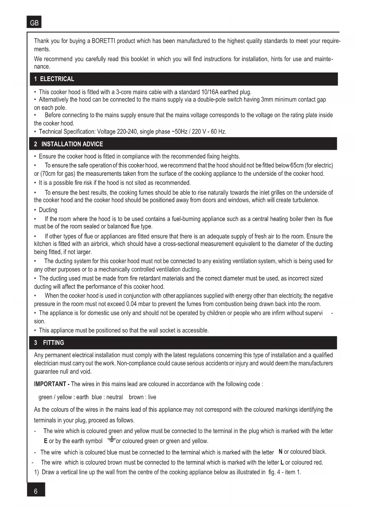
Receiver Remote control On / Off Light Led F On / Off Motor Speed Control Led C Intensive SpeedA - EXTRACTION OR RECYCLING
Your cooker hood is supplied in the extraction mode. To use the cooker hood in the recirculation mode re-programme the hood as follows:
Starting in the recirculation mode
Press the '+' button for 10 seconds (while the motor and lights are switched 'OFF') and the two LED lights will flash twice to indicate confirmation that the cooker hood is in the recycling mode.
Reverting to the extraction mode
Press the '+' button for 10 seconds (while the motor and lights are switched 'OFF') and the two LED lights will flash once to indicate confirmation that the cooker hood is in the extraction mode.
B - BASIC INSTRUCTIONS
Lighting
Press Button 1 to switch 'ON' the lights.
Motor
Press LED button 2 to switch 'ON' the fan motor, the LED F will illuminate to confirm the motor is switched 'ON', and adjust the speed of the fan motor by pressing the Button '+' and '-''. The fan speed will be increased if constant pressure is kept on the (+) button.
Press LED button 5 to obtain the boost position for maximum effect and the LED C will illuminate to confirm fan is switched 'ON'.
C - COMPLEMENTARY INSTRUCTIONS
Automatic pre-set stop for the boost speed after 10 mn.
To obtain the best performance it is advisable to switch 'ON' the cooker hood a few minutes (in the boost setting) before you start cooking and you should leave it running for approximately 10 minutes after finishing.
Press LED button 5 to switch 'OFF' the fan motor immediately.
Indication of saturation of the metal grease filters
After 100 hours use, one quick flash of the LED F will indicate that you must clean the metal grease filters. (See chapter on 'Maintenance').
This indication is not available when the fan motor is switched OFF.
Indication of saturation of the active charcoal filter
After 200 hours use, two quick flash of the LEDS F & C will indicate that you must replace the active charcoal filter and clean
the metal grease filters. (See chapter on 'Maintenance').
To reset the 200-hour timer the motor and lights must be switched 'OFF'.
Push the LED button '+' for 10 seconds.
One flash of the LED lights F and C = function is switched 'OFF'.
Two flashes of the LED lights F and C = function is switched 'ON'.
To reset the 100 hours timer back to zero requires the motor and lights must be switched 'OFF'; then and proceed as follows:
Press the LED button ‘+’ for 3 to 4 seconds and the LED lights F and C will flash to confirm the programme has been reset to zero.
Instructions for replacing the active charcoal filter are given in the chapter on 'Recycling'.
Setup Process
Modification: How to adjust the internal microprocessor data to suit the type of motor fitted to this appliance and the supply frequency of 50 or 60 Hz..
1 - Disconnect the cooker hood from the mains supply.
2 - Push the button 0/1 MOTOR.
3 - Reconnect the mains supply while pushing the button 0/1 MOTOR for at least 2 seconds.
4 - Slacken the button 0/1 MOTOR (the Leds flash for about 3 seconds : capacity's confirmation SETUP PROCESS).
5 - During the flashing time select the motor type used while pushing one of the 5 buttons according to the following board:
BUTTON 0/1 Light : Motor 8/28 & 8/50 220-240 V AC / 50 Hz.
BUTTON 0/1 Motor : Motor 8/28 & 8/50 220-240 V AC / 60 Hz.
BUTTON Speed (-) : Motor PRO 220-240 V AC / 50 Hz.
BUTTON Speed (+) : Motor PRO 220-240 V AC / 60 Hz.
BUTTON Intensive speed : Motor K40 & K50 220-240 V AC / 50 Hz.
REMOTE CONTROL HANDSET
Caution, the remote control must be fitted with standard LR03-AAA size 1.5V zinc-carbon alkaline batteries as illustrated Fig. 9. These batteries should give a long life and constant discharge throughout their life.
These batteries must be disposed of properly and could explode if damaged or exposed to heat. Do not dispose of on fire.
5 USEFUL HINTS
- To obtain the best performance it is advisable to switch 'ON' the cooker hood a few minutes (in the boost setting) before you start cooking and you should leave it running for approximately 15 minutes after finishing.
• IMPORTANT: NEVER DO FLAMBÉ COOKING UNDER THIS COOKER HOOD - Do not leave frying pans unattended during use as over-heated fat and oil might catch fire.
• Do not leave naked flames under this cooker hood. - Switch 'OFF' the electric and gas before removing pots and pans.
- Ensure heating areas on your hotplate are covered with pots and pans when using the hotplate and cooker hood simultaneously.
6 MAINTENANCE
Before carrying out any maintenance or cleaning isolate the cooker hood from the mains supply.
The cooker hood must be kept clean; a build up of fat or grease can be a fire hazard.
Casing
- Wipe the cooker hood frequently with a clean cloth, which has been immersed in warm water containing a mild detergent and wrung out.
- Never use excessive amounts of water when cleaning particularly around the control panel.
- Never use scouring pads or abrasive cleaners.
• Always wear protective gloves when cleaning the cooker hood.
Metal Grease Filters
The metal grease filters absorb grease and dust during cooking to help keep the cooker hood clean inside. The grease filters should be cleaned once a month or more frequently if the hood is used for more than 3 hours per day.
To remove and replace the metal grease filters
- Remove the metal grease filters one at a time by releasing the catches on the filters; the filters can now be removed.
- The metal grease filters should be washed, by hand, in mild soapy water or in a dishwasher.
- Allow to dry before replacing.
Active Charcoal Filter
The charcoal filter cannot be cleaned. The filter should be replaced at least every three months or more frequently if the hood is used for more than three hours per day.
To remove and replace the filter
- Remove the metal grease filters.
- Press against the two retaining clips, which hold the charcoal filter in place and this will allow the filter to drop down and be removed.
- Clean the surrounding area and metal grease filters as directed above.
- Insert the replacement filter and ensure the two retaining clips are correctly located.
- Replace the metal grease filters.
Extraction tube.
Check every 6 months that the dirty air is being extracted correctly. Comply with local rules and regulations with regard to the extraction of ventilated air.
Lighting.
If the lamp fails to function check to ensure it is fitted correctly into the holder. If lamp failure has occurred then it should be replaced with identical replacement.
Do not replace with any other type of lamp and do not fit a lamp with a higher rating.
7 GUARANTEE AND AFTER SALES SERVICE
- In the event of any malfunction or anomaly, notify your fitter who will have to check the appliance and its connection.
- In the event of damage to the mains supply cable, this can only be replaced by at approved repair centre appointed by the manufacturer who have the necessary tools and equipment to carry out any repairs properly. Repairs carried out by other persons will invalidate the guarantee.
• Use only genuine spare parts. Should these warnings fail to be observed it could affect the safety of your cooker hood. - When ordering spare parts quote the model number and serial number written on the rating plate, which is found on the casing behind the grease filters inside the hood.
• Proof of purchase will be required when requesting service. Therefore, please have your receipt available when requesting service as this constitutes the date from which your guarantee commenced.
This Guarantee does not cover :
- Damage or calls resulting from transportation, improper use or neglect, the replacement of any light bulbs or filters or removable parts of glass or plastic. These items are considered to be consumable under the terms of this guarantee.
8 REMARKS
Your appliance comply with harmonised standards CEI 335 and the Europeans' directives (Low voltage) 73/23 and (Electromagnetic compatibility) 89/336.
3 INSTALLATIE VAN HET APPARAAT
text_image
Exploded view diagram of a kitchen range hood with labeled parts including air filters, washers, and accessories1

text_image
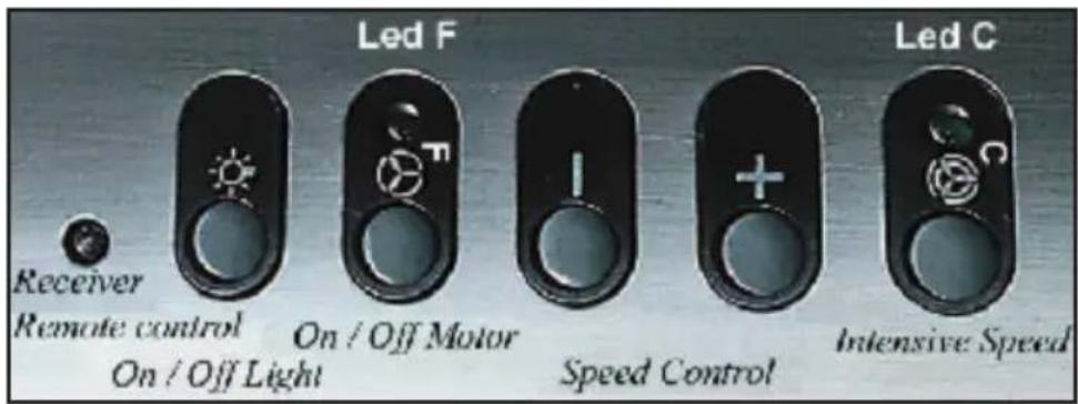
300 260 600 621 40° 540 1250 - 1580 25 580 450 1000 - 900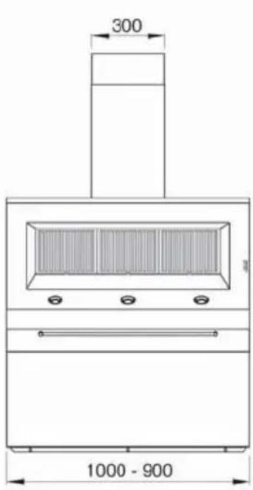
text_image
300 1000 - 900
text_image
Ø 150
text_image
600 260 540 1250 - 1580 580 450 15 621 40° 252

text_image
T V1 V2 T C B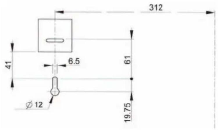
text_image
312 41 6.5 61 Ø 12 19.753

text_image
② ② X 312 312 18 580 d B
text_image
B H = 450 mm5

natural_image
Diagram showing a downward arrow and a cylindrical container with internal structure (no text or symbols)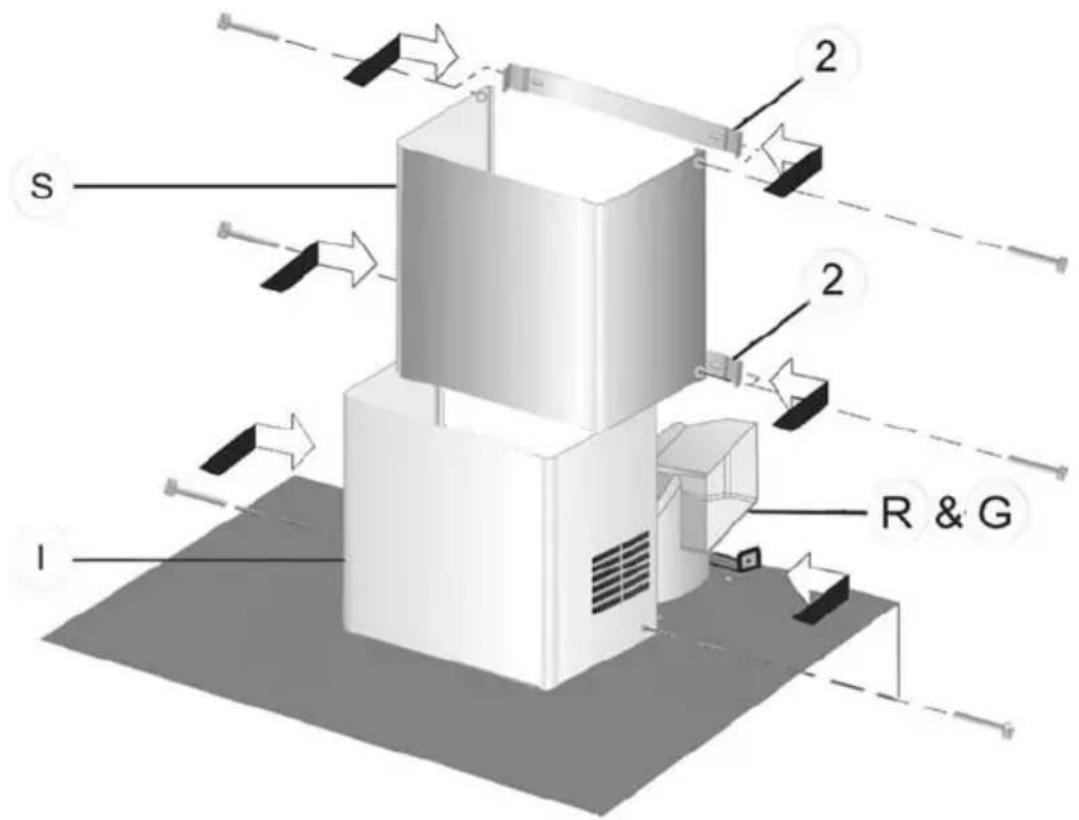
text_image
S I 2 2 R & G6

Avec recyclage
Mit Umluftbetrieb
Con reciclaje
With recirculation
natural_image
Diagram of a mechanical device with two crossed lines and directional arrows, no text or symbols present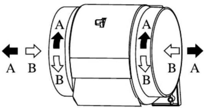
natural_image
Diagram of three mechanical components with arrows indicating assembly or movement, no text or symbols present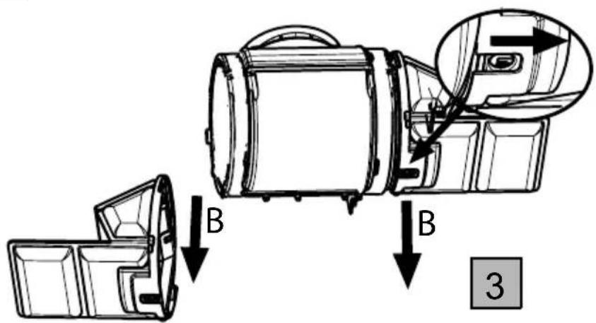
text_image
Technical diagram showing mechanical assembly steps with labeled components and directional arrows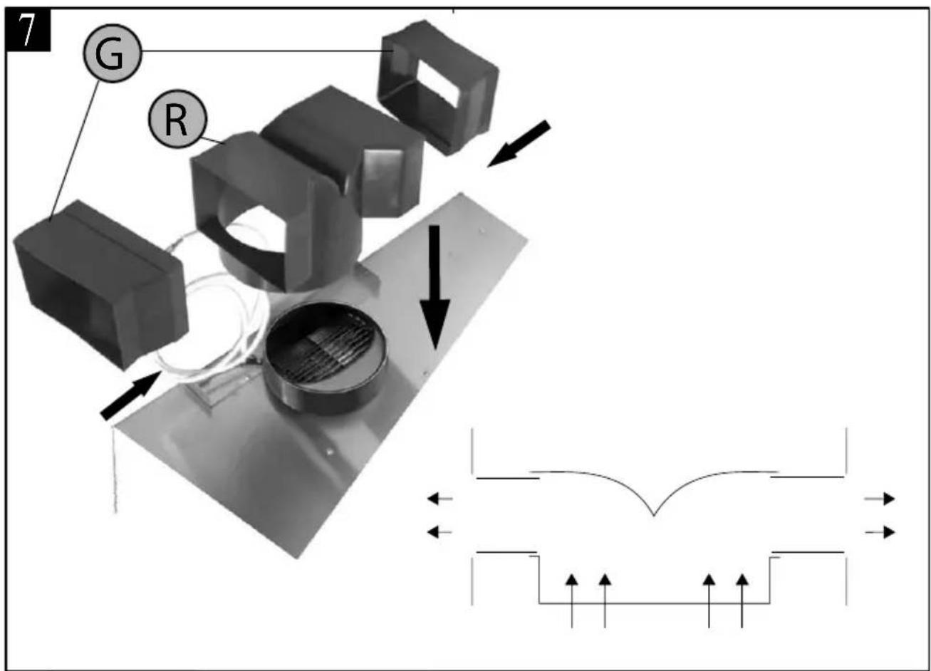
text_image
7 G R
text_image
8 A B A B A B A S15_09
text_image
LR03 / AAA / 1,5V 1 2 9 10 1112

text_image
Ø 200 mm
text_image
HALOGEN BELEUCHTUNG HALOGEN LIGHT 3 x 20 W - 12 V LAMPES HALOGENES TRANSFORMATOR TRANSFORMATEUR TRANSFORMER Blue White Brown Black M L M L F N 6 5 4 3 2 1 Light-Blue Brown Green-Yellow G-Y 10 µF 400 V kcalR Grey White Azur Brown Yellow M 350 W 220 - 240 V 50Hz 220 - 60Hz MOI-FLACH KABEL AMIDE ANXYE FLAT CABLE CONN. RX IR ELEKTRONISCHE STEUERUNG BOITIER COM DRA PUSH BUTTON PANEL GENIEN RECEPTEUR INFRAROUGE REMOTE CONTROL NBE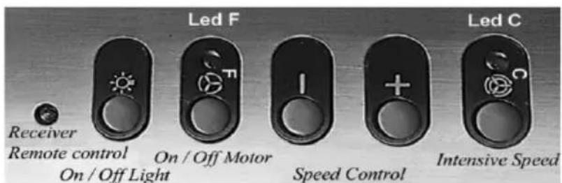
text_image
Receiver Remote control On / Off Light Led F On / Off Motor Speed Control Led C Intensive Speed
PRO 1000 IX
PRO 900 IX
( Wall mounted from )
3S_Pro_M_90_100_IX_V2006-07
MAJ (UPDATE) : 24/07/06
TECHNICAL INFORMATION (UK)

It is dangerous to alter the specifications or attempt to modify this product in any way.
ELECTRICAL SUPPLY
VOLTAGE: (50Hz) 230V
POWER CONSUMPTION: 410W
FAN MOTOR: 350W
LIGHT BULB: 3 x 20W 60W
PERFORMANCE SPEEDS Electronic
CAPACITY m ^3 /h ^* 770-875
CAPACITY m ^3 /h ^** 930-1050
PRESSURE PA 340
NOISE LEVEL dBA***68-39
*IEC 61591 method for cooker hoods in evacuation mode - ** IEC 61591 method with free delivery - ***IEC 60704-2-13 method This appliance conforms to BS.800:1988 and EEC Directive No. 78 308 regarding suppression of radio and television interference.

Note: CE Marking certifies that this appliance complies with the requirements laid down in EEC directive 89:336 (Electromagnetic compatibility) and subsequent modifications and Low Voltage directive 72/23/E.
ELECTRICAL CONNECTION

THIS APPLIANCE MUST BE EARTHED
ELECTRICAL REQUIREMENTS
Any permanent electrical installation must comply with the latest I.E.E. Regulations and local Electricity Board regulations. For your own safety this should be undertaken by a qualified electrician e.g. your local Electricity Board, or a contractor who is on the roll of the National Inspection Council for Electrical Installation Contracting (NICEIC).
ELECTRICAL CONNECTION
Before connecting to the mains supply ensure that the mains voltage corresponds to the voltage on the rating plate inside the cooker hood.
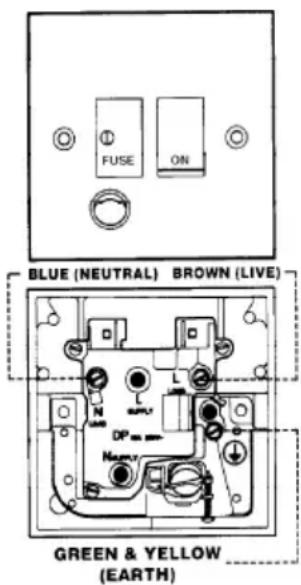
This appliance is fitted with two 3 core mains cable and must be permanently connected to the electricity supply via two double-pole switch having 3 mm minimum contact gap on each pole. Two Switched Fuse connection units to BS.1363 Part 4, fitted with a 3 Amp. fuse are a recommended mains supply connection accessory to ensure compliance with the safety requirements applicable to fixed wiring intructions.
text_image
FUSE ON BLUE (NEUTRAL) BROWN (LIVE) GREEN & YELLOW (EARTH)The wires in this mains lead are coloured in accordance with the following code:-
Green & Yellow Earth
Blue Neutral
Brown Live
As the colours of the wires in the mains lead of this appliance may not correspond with the coloured markings identifying the terminals in your connection unit, proceed as follows:-
The wire which is coloured green and yellow must be connected to the terminal which is marked with the letter 'E' or by the earth symbol of coloured green and yellow.
The wire which is coloured blue must be connected to the terminal which is marked with the letter 'N' or coloured black.
The wire which is coloured brown must be connected to the terminal which is marked with the letter 'L' or coloured red.
natural_image
Symbol of a trash bin crossed with two crossed lines, no text or labels presentGB - Your product is designed and manufactured with high quality materials and components, which can be recycled and reused.
When this crossed-out wheeled bin symbol is attached to a product it means the product is covered by the European directive 2002/96/EC.
Please inform yourself about the local separate collection system for electrical and electronic product.
Please act according to your local rules and do not dispose of your old products with your normal household waste. The correct disposal of your old product will help prevent potential negative consequences for the environment and human health.
This appliance complies with European regulations on low voltages, EEC Directive 73/23 on electrical safety, and with the following European regulations: EEC Directive 89/336 on electromagnetic compatibility and EEC Directive 93/68 on EC marking.
The Netherlands Belgium
T +31(0)20-4363439 T +32(0)3-4508180
F +31(0)20-4361326 F +32(0)3-4586847
E info@boretti.com E info.be@boretti.com
www.boretti.com www.boretti.com
BORETTI s.l.