AL 1 - Exercise bike Christopeit - Free user manual and instructions
Find the device manual for free AL 1 Christopeit in PDF.
User questions about AL 1 Christopeit
0 question about this device. Answer the ones you know or ask your own.
Ask a new question about this device
Download the instructions for your Exercise bike in PDF format for free! Find your manual AL 1 - Christopeit and take your electronic device back in hand. On this page are published all the documents necessary for the use of your device. AL 1 by Christopeit.
USER MANUAL AL 1 Christopeit
natural_image
Exterior view of a white exercise bike with black and silver body, no visible text or symbols
natural_image
Black exercise bike with visible branding and circular head (no text or symbols on body)Assembly and exercise instructions for Order No. 1106(A)/11062
F
text_image
Technical diagram of a mechanical device with numbered components and labeled partsSchritt 2: Montage der Pedalen (22L+22R) an den Pedalarmen (21L+21R).
text_image
Technical diagram of a mechanical device with labeled parts and directional arrows indicating motion or assembly.Schritt 3:
text_image
Technical diagram of a stationary exercise bike with numbered parts for identificationtext_image
Technical diagram of a stationary exercise bike with numbered components for identificationSchritt 6: Kontrolle
natural_image
Line drawing of a stationary exercise bike with adjustable arms and wheels (no text or symbols)Garantiebestimmungen
natural_image
Diagram of a mechanical device with a lever and cable, showing motion direction (no text or symbols)Wichtig:
text_image
CHSSTOCAT 4:32 STOP TIME E F L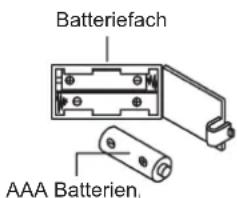
text_image
Batteriefach AAA Batterien₁natural_image
Sequence of four sequential illustrations showing a person performing a stretching or kneeling movement (no text or symbols)- Summary of Parts Page 3
- Important Recommendations and Safety Information Page 13
- Assembly Instructions With Exploded Diagrams Page 14-16
- Mount, Use & Dismount Page 17
- Computer instructions Page 18
- Cleaning, Storage, Checks, Troubleshooting, Page 19 Warm up exercises (Warm Up)
- Training Instructions Page 20
- Parts List Page 21-22
- Exploded view Page 75
Dear customer,
We congratulate you on your purchase of this home training sports unit and hope that we will have a great deal of pleasure with it. Please take heed of the enclosed notes and instructions and follow them closely concerning assembly and use. Please do not hesitate to contact us at any time if you should have any questions.
Read the user manual before use!
Important Recommendations and Safety Instructions
Our products are all tested and therefore represent the highest current safety standards. However, this fact does not make it unnecessary to observe the following principles strictly.
- Assembly the machine exactly as described in the installation instructions and use only the enclosed, specific parts of the machine. Before assembling, verify the completeness of the delivery against the delivery notice and the completeness of the carton against the assembly steps in the installation and operating instructions.
- Before the first use and at regular intervals (approximately every 50 Operating hours) check the tightness of all screws, nuts and other connections and the access shafts and joints with some lubricant so that the safe operating condition of the equipment is ensured. In particular, the adjustment of saddle and handlebar need smooth function and good condition.
- Set up the machine in a dry, level place and protect it from moisture and water. Uneven parts of the floor must be compensated by suitable measures and by the provided adjustable parts of the machine if such are installed. Ensure that no contact occurs with moisture or water.
- Place a suitable base (e.g. rubber mat, wooden board etc.) beneath the machine if the area of the machine must be specially protected against indentations, dirt etc.
- Before beginning training, remove all objects within a radius of 2 metres from the machine.
- Do not use aggressive cleaning agents to clean the machine and employ only the supplied tools or suitable tools of your own to assemble the machine and for any necessary repairs. Remove drops of sweat from the machine immediately after finishing training.
- WARNING! Systems of the heart frequency supervision can be inexact. Excessive training can lead to serious health damage or to the death. Consult a doctor before beginning a planned training programme. He can define the maximum exertion (pulse, Watts, duration of training etc.) to which you may expose yourself and can give you precise information on the correct posture during training, the targets of your training and your diet. Never train after eating large meals.
- Only train on the machine when it is in correct working order. Use original spare parts only for any necessary repairs. WARNING! Replace the worm parts immediately and keep this equipment out of use until repaired.
- When setting the adjustable parts, observe the correct position and the marked, maximum setting positions and ensure that the newly adjusted position is correctly secured.
-
Unless otherwise described in the instructions, the machine must only be used for training by one person at a time. The exercise time should not overtake 60 min./daily.
-
Wear training clothes and shoes which are suitable for fitness training with the machine. Your clothes must be such that they cannot catch during training due to their shape (e.g. length). Your training shoes should be appropriate for the trainer, must support your feet firmly and must have non-slip soles.
- WARNING! If you notice a feeling of dizziness, sickness, chest pain or other abnormal symptoms, stop training and consult a doctor.
- Never forget that sports machines are not toys. They must therefore only be used according to their purpose and by suitably informed and instructed persons.
- People such as children, invalids and handicapped persons should only use the machine in the presence of another person who can give aid and advice. Take suitable measures to ensure that children never use the machine without supervision.
- Ensure that the person conducting training and other people never move or hold any parts of their body into the vicinity of moving parts.
- At the end of its life span this product is not allowed to dispose over the normal household waste, but it must be given to an assembly point for the recycling of electric and electronic components. You may find the symbol on the product, on the instructions or on the packing. The materials are reusable in accordance with their marking. With the reuse, the material utilization or the protection of our environment. Please ask the local administration for the responsible disposal place.
- To protect the environment, do not dispose of the packaging materials, used batteries or parts of the machine as household waste. Put these in the appropriate collection bins or bring them to a suitable collection point.
- This machine is a speed-dependant machine, i.e. the power increases with increasing speed, and the reverse.
- The machine is equipped with 8-speed resistance adjustment. This makes it possible to reduce or increase the braking resistance and thereby the training exertion. Turning the adjusting knob for the resistance setting towards stage 1 reduces the braking resistance and thereby the training exertion. Turning the adjusting knob for the resistance setting towards stage 8 increases the braking resistance and thereby the training exertion.
- The maximum permissible load (=body weight) is specified as 150 kg. This machine has been tested and certified in compliance with EN ISO 20957-1:2013 und EN ISO 20957-5:2016 „H/C“. This item's computer corresponds to the basic demands of the EMV Directive of 2014/30/EU.
- The assembly and operating instructions is part of the product. If selling or passing to another person the documentation must be provided with the product.
Assembly Instructions
Remove all the separate parts from the packaging, lay them on the floor and check roughly that all are there on the base of the assembly steps. Please note that a number of parts have been connected directly to the main frame and preassembled. In addition, there are several other individual parts that have been attached to separate units. This will make it easier and quicker for you to assemble the equipment. Assembly time: 30 - 40 min.
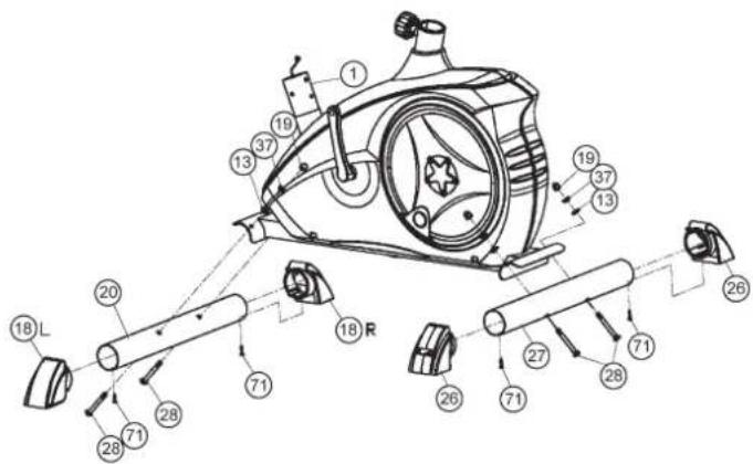
Step 1: Attach the stabilizer (20+27) at main frame (1).
- Put the end caps with transportation roller (18) at the ends of front foot (20) in appropriate position and screw them tightly by using screw (71).
- Attach the short front foot (20) with the preassembled end caps with transportation rollers (18) to the main frame (1). Do this with the two screws (28), washers (13), spring washers (37) and cap nuts (19).
- Put the end caps with height adjustment (26) at the ends of rear foot (27) and screw them tightly by using screw (71).
- Attach the longer rear foot (27) to the main frame (1). Do this with the two screws (28), washers (13), spring washers (37) and cap nuts (19). After assembly has been completed, you can compensate for minor irregularities in the floor by turning the wheel at cap (26). The equipment should be set up that the equipment does not move of its own accord during a training session. If you like to change the position of the home bike, put one foot in front of the front foot (20) and pull at handlebar in front direction until the home bike can move easy on the transportation rollers to another place.
text_image
Technical diagram of a mechanical device with numbered components and labeled partsStep 2: Attach the pedals (22L+22R) at pedal crank (21L+21R).
- Screw the right pedal (22R) into the locator in the right-hand side (as seen in operation) for the pedal crank (21R) (warning! the screw direction is clockwise).
- Screw the left pedal (22L) into the locator in the left-hand side (as seen in operation) for the pedal crank (21L) (Warning! the screw direction is anti-clockwise).
- Then mount the pedal straps left and right on the associated pedals (22). (The pedals are signed with „L“ for Left and „R“ for Right.) (Note: The end with many adjustable holes must be set outwards.)

text_image
Technical diagram of a stationary exercise machine with labeled components and rotation indicatorsStep 3: Attach the front post (12) at main frame (1).
- Slide the handlebar support cover (38) onto the handlebar support (12). Place the screws (14), washers (13) and sprig washers (37) on the floor.
- Hold the handlebar support (12) with the computer cable (3) against the main frame holder. Connect the plug for the computer cable (3) coming out of the bottom of the handlebar support (12) of the computer with the matching plug for the sensor cable (16) coming out of the main frame (1).
(Note: The computer cable harness (3) projecting from the support (3) must not slide into the tube, as it is required for later steps of installation.) - Connect the resistance control (11) to the bracket of lower section cable tension (15) (See figure [1]-[3]). Before this step of the installation, it is advisable to adjust the resistance setting to the highest stage, at which the cable extends furthest from the sheath. Put the lowest part of cable (11) into the small hook (figure 1). Pull it (figure 2) until the small hook get in higher position and then insert the cable (11) onto the bracket (15) (figure 3).
- Place the handlebar support (12) in the locator provided for it in the main frame (1). Ensure that the cable connections made in step 3 are not squashed. When putting the steering tube in place, push the former slowly down into the locator in the main frame. Screw the handlebar support (12) onto the base frame (1) with the screws (14), spring washers (37) and washers (13).
- Push the handlebar support cover (38) into right position to cover up the screw connection point.
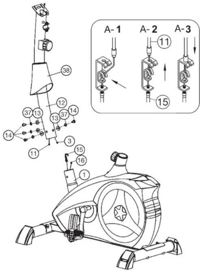
text_image
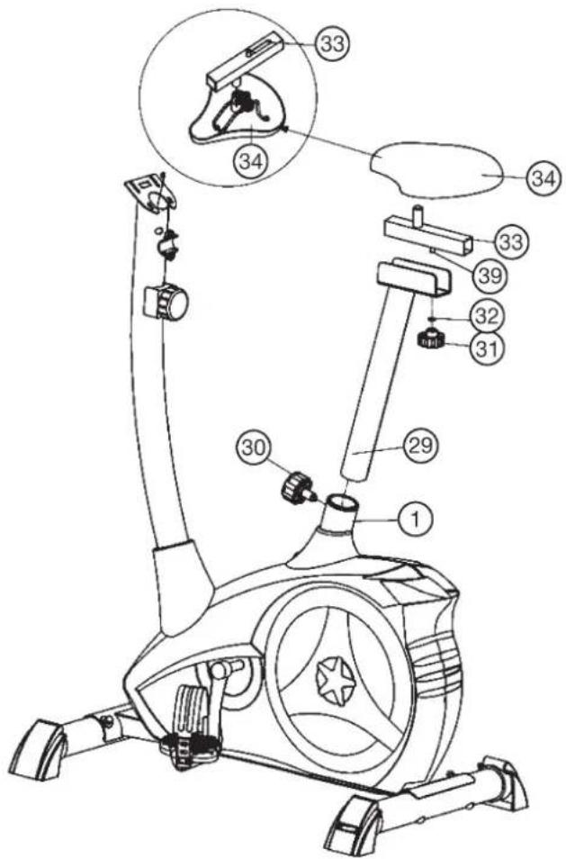
A-1 A-2 A-3 11 15 14 38 37 13 12 14 13 37 11 3 15 16 1Step 4: Attach the saddle (34) and saddle slide (33) at saddle support (29) and the saddle support (29) at main frame (1).
- Push the saddle (34) with saddle bracket into the saddle slide (33) and tight it up in desired position. To do it, both black nuts must be tightened.
- Place the saddle slide (33) into the holder of saddle support (29), set it at the desired horizontally position and screw it onto the saddle support (29) by fixing piece (39) washer (32) and star grip nut (31).
- Push the saddle support tube (29) into the matching locator in the main frame (1), set it at the desired position and lock it by inserting the bolt with the quick release (30) in place and doing it up tight.
(The setting of the saddle support can be adjusted easily as desired later through turning and pulling the quick release (30).) Furthermore, you must ensure when setting this desired position that the seat pillar is not pulled out of the main frame further than the highest setting position, which is marked. Attention: Ensure before every exercising that the saddle is tighten firmly.
text_image
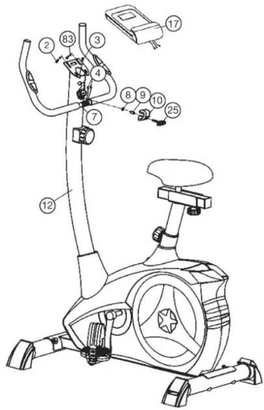
Technical diagram of a stationary exercise bike with numbered parts for identificationStep 5:
Attach the handlebar (7) and computer (17) at handlebar support (12).
- Guide the preassembled handlebar unit (7) through the upper part of the handlebar post (12) and push the pulse cable (4) through the holes at handlebar support into top position and close the bracket of handlebar holder.
- Attach the handlebar cover (10) at the handlebar holder.
- Screw the handlebar (7) in desired position at the handlebar post (12) with spacer (9), washer (8) and handlebar screw (25).
- Push the plugs of the connecting cable (3) and pulse cable (4) projecting from the handlebar support (12) into the associated socket of the computer (17).
- Take the computer (17) that has been supplied out of the packaging and insert the batteries (Type "AAA"-1.5 V pencells) by watching for the right polarity on the back of the computer (17). (Batteries for the computer are not included in this item. Please buy them at your located market.)
- Place the computer (17) on top of the handlebar support (12) and tight firmly by using screw (2) and washers (83).
text_image
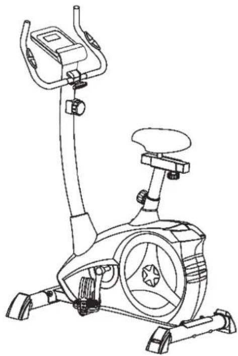
Technical diagram of a stationary exercise bike with numbered components for identificationStep 6:
Checks
- Check the correct installation and function of all screwed and plug connections.
Installation is thereby complete. - When everything is in order, familiarise yourself with the machine at a low resistance setting and make your individual adjustments.
Note:
Please keep the tool set and the instructions in a safe place as these may be required for repairs or spare parts orders becoming necessary later.
natural_image
Line drawing of a stationary exercise bike with adjustable arms and wheels (no text or symbols)Mount, Use & Dismount
Transportation of Equipment:
There are two rollers equipped on the front foot. For moving, you can lift up the rear foot and drive it to where you would like to locate or store it.
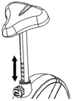
Adjustment – Seat Position
For an effective workout, the seat must be adjusted properly. While your are pedaling, your Knees should be slightly bent when the pedals are in the farthest position. In order to adjust the seat, unscrew the knob few turns and draw it out slightly. Adjust the seat to the right height, then release the knob and tighten it all the way.
natural_image
Diagram of a mechanical device with a vertical rod and two arrows indicating upward motion (no text or symbols)Important:
Make sure to put the knob back into place in the seat post and tighten it completely. Never exceed the maximum height of the seat. Always get off the bicycle before making any adjustment.
A biomechanically optimal seating position ensures optimum power transmission. The aim is that the existing force as large as possible arrives on the pedals and the muscles with optimal effect works. The seat position affects which muscles are in use primarily in essence. The right handlebar position is responsible for keeping the upper body portion. Is the handlebar settings chosen horizontally so you get an athletic posture. With each further step towards the body, you adjust a more relaxed attitude. To adjust the handlebar, simply loosen the screw handlebar until the handlebar can brought into the desired position and tighten them after adjustment again firmly.
To avoid any problems such as back-/ knee pain or numbness in the feet through bad seat position on the bike, the maintenance of a proper adjustment of the saddle and handlebar we strongly recommend.
Mount, Use & Dismount
Mount:
a. After the seat is adjusted to properly position, insert your foot into retaining strap of pedal step on the pedal and hold the handlebar tightly.
b. Try to put whole body weight on your foot and simultaneously cross over the trainer and land your another foot on the other side.
c. Now you are in the position to start your training.
Use:
a. Keep you hands on the handlebar, and both feet are insert into retaining straps of both pedal properly.
b. Pedal your exercise bike by your both feet alternately.
c. Then you can increase the pedaling speed gradually and adjust braking resistance levels to increase the exercise intension.
Dismount:
a. Slow down the pedaling speed until it comes to rest.
b. Keep the left hand grabbing the left handlebar tightly, put your feet cross over the equipment and land on the floor, then land the other one.
This training equipment is a stationary exercise machine used to simulate without causing excessive pressure to the joints, hence decreasing the risk of impact injuries.
Exercise bike offer a non-impact cardiovascular workout that can vary from light to high intensity based on the resistance preference set by the user. It will strengthen your muscles of legs and increase cardio capacity and maintain fitness of your body also.
Computer instructions
The supplied computer allows the most convenient training. Every value relevant to training is displayed in a corresponding window. From the beginning of the training session, the required time, the current speed, the approximate calorie consumption, the travelled distance ad the current pulse rate are displayed. All values are counted from zero upwards. If you wish to see one value displayed constantly during training, select this with the „F“ key. If you wish to see these values in constant alternation, select the „SCAN“ function. The display then changes from one function to the next at intervals of approx. 6 seconds.
The computer is switched on by briefly pressing the F-key or simply by beginning training. The computer begins to register and display all values. To stop the computer, just stop training. The computer stops all measurements and retains the last attained values. The last attained values in the functions TIME, CALORIES and KM are stored for 4 minutes and training can continue with these values when training is resumed. The computer switches of automatically approx. 4 minutes after training is stopped. All values attained until that time are stored and are displayed again when training is resumed. It is then possible to continue training from these values or to reset all functions to zero using the L-key.
Displays:
1. „SPEED“ (KM/H) display:
The current speed is displayed in kilometres per hour. It is not possible to specify a particular value using the „E“ key. The values last attained by this function are not stored. (Limit of the display: 999.9 km/h.)
The currently required time is displayed in minutes and seconds. It is possible to specify a particular value using the „E“ key. If a particular time has been specified, the remaining time is displayed. When the specified value is attained, this is indicated by an acoustic signal. The values last attained by this function are stored. (Limit of the display: 99 minutes.)
3. „DIST (KM)“ display:
The current status of the travelled distance is displayed. It is possible to specify a particular value using the „E“ key. If a particular distance has been specified, the remaining distance is displayed. When the specified value is attained, this is indicated by an acoustic signal. The values last attained by this function are stored. (Limit of the display: 999,9 km.)
4. „CALORY“ (CAL) display:
The current status of the consumed calories is displayed. It is possible to specify a particular value using the „E“ key. If a particular consumption has been specified, the remaining number of calories to be consumed is displayed. When the specified value is attained, this is indicated by an acoustic signal. The values last attained by this function are stored. (Limit of the display: 999,0 calories.)
5. „PULSE“ display:
The current pulse rate is displayed in beats per minute. It is possible to specify a particular value using the „E“ key.
The values last attained by this function are not stored. (Limit of both displays: 40 - 240 pulse beats per minute.)
Note:
For pulse measurement, the two contact surfaces of the pulse measuring handle unit must be gripped simultaneously. The contact surfaces should be located centrally in the palms of the hands.
6. „SCAN“ function:
If this function is selected, the current values of all functions are displayed successively in a constant sequence approx. every 5 seconds.
7. „STOP“ display:
Display of Stopmode. Presets can be set.
Keys:
1. „F“ key (Fuction):
Pressing this key once briefly makes it possible to change from one function to another, i.e. the respective functions can be selected for which entries can be made using the "E" key. The currently selected function is indicated in the window.
2. „E“ key (Enter):
By pressing this key once, it is possible to specify values step by step in the respective functions. For this, the desired function must firstly be selected using the „F“ key.
Holding the key pressed activates faster running. When training begins, the specified values are then counted down to zero.
3. „L“-key = (Delete):
When this key is pressed briefly, the values chosen with the „F“ key are reset to zero. If the key is held longer (approx. 3 seconds), all last attained values are deleted.

text_image
CHIRITOSET 4:32 STOP TIME E F LBattery compartment
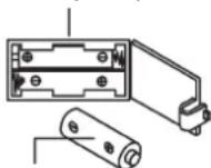
AAA batteries
Replacing the batteries:
- Open the battery compartment cover and then remove the used Batteries. (If the batteries should leak remove them under increased considering that the battery acid is not into contact with skin come and clean the battery compartment thoroughly.)
- Insert the new batteries (type (AAA) 1.5 V in the correct order and taking into account the polarity in the battery compartment and close the battery cover so that it clicks into place.
- If the computer does not pick up immediately, the function should Batteries are removed for 10 seconds and re-inserted.
- The empty batteries properly in accordance with the disposal regulations disposed of and do not give residual waste.
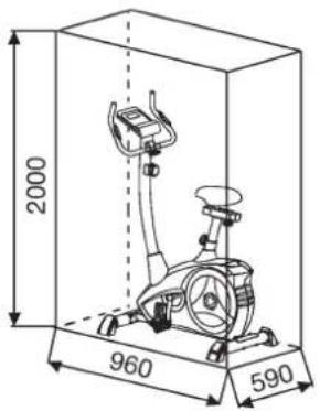
Training area in mm (for home trainer and user)
Free area in mm (Training area and security area (rotating 60cm))
text_image
2000 960 590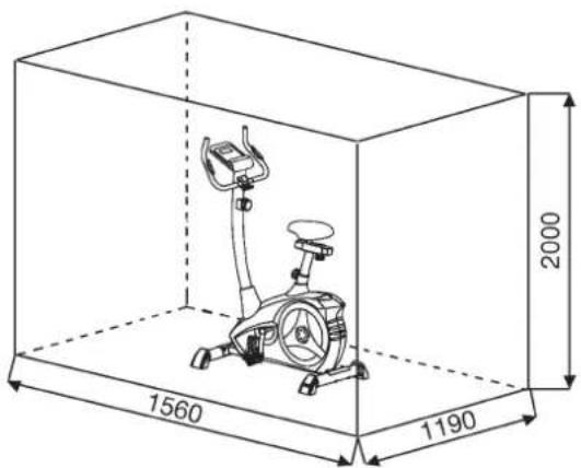
text_image
1560 1190 2000Cleaning, Checks and Storage of the home bike:
1. Cleaning
Use only a less wet cloth for cleaning.
Caution: Never use benzene, thinner or other aggressive cleaning agents for surface cleaning as this damage caused.
The device is only for private home use and for use suitable indoors. Keep the unit clean and moisture from the device.
2. Storage
Remove the batteries from the computer while intending the unit for more than 4 weeks not to use. Push the saddle slide toward the handlebar and the seat support tube as deeply as possible into the frame. Choose a dry storage in-house and put some spray oil to the pedal bearings left and right, to the thread of the handlebar bolt, and on the thread of the quick release for saddle support.
Cover the bike to protect it from being discolor by any sunlight and dirty through dust.
3. Checks
We recommend every 50 hours to review the screw connections for tightness, which were prepared in the assembly. Every 100 operating hours, you should put some spray oil at the pedal bearings left and right, to the thread of the handlebar bolt and to the thread of quick release for saddle support.
Troubleshooting
If you cannot solve the problem with the following information, please contact the authorized service center.
| Problem Possible Cause Solution | ||
| Computer has no value at Display if you press any key. | No Batteries insert or batteries empty | Check the position of batteries at battery compartment or replace batteries. |
| Computer is not counting data and do not switch on after start cycling. | Sensor impulse missing base on not well plugged connection | Check the plug connections at computer and inside of handle-bar support. |
| Computer is not counting data and do not switch on after start cycling. | Sensor impulse missing base on not correct position of sensor. | Take off the cover and check the distance between magnet and Sensor. The magnet at turning belt wheel should have only less than < 5mm distance against the sensor position. |
| No pulse value | Pulse cable is not plugged in. | Check the separately pulse cable is well connected with computer. |
| No pulse value | Pulse sensors not well connected | Screw out the screw for pulse measurement and check if plugs are well connected and no damage at pulse cable. |
| Resistance don't change | Connection of resistance not well | Check the resistance connection inside of handlebar support as manual mention. |
General training instructions
You must consider the following factors in determining the amount of training effort required in order to attain tangible physical and health benefits.
INTENSITY
The level of physical exertion during training must exceed the point of normal exertion, without going beyond the point of breathlessness and/or exhaustion. A suitable reference value can be the pulse. With each training session, the condition increases and therefore the training requirements should be adjusted. This is possible by extending the duration of the training, increasing the level of difficulty or changing the typ training.
TRAINING HEART RATE
To determine the training heart rate, you can proceed as follows. Please note that these are guide values. If you have health problems or are unsure, consult a doctor or fitness trainer.
01 Maximum heart rate calculation
The maximum pulse value can be determined in many different ways, since the maximum pulse depends on many factors. You can use the main-formula for the calculation (maximum heart rate = 220 - age). This formula is very general. It is used in many home sport products to determine the maximum heart rate. We recommend the Sally-Edwards-formula. This formula calculates the maximum heart rate more precisely and takes gender, age and body weight into account.
Sally-Edwards-formula:
Men:
Maximum heart rate = 214 - (0.5 x age) - (0.11 x body weight)
Women:
Maximum heart rate = 210 - (0.5 x age) - (0.11 x body weight)
02 Training heart rate calculation
The optimal training heart rate is determined by the goal of the training. Training zones were defined for this.
Health - Zone: Regeneration and Compensation
Suitable for: Beginners
Type of training: very light cardio training
Goal: recovery and health promotion. Building the basic condition.
Training heart rate = 50 to 60% of the maximum heart rate
Fat-Metabolism - Zone: Basics endurance training 1
Suitable for: beginners and advanced users
Type of training: light cardio training
Goal: activation of fat metabolism (calorie burning). improvement in endurance performance.
Training heart rate = 60 to 70% of the maximum heart rate
Aerobic - Zone: Basics endurance training 1 to 2
Suitable for: beginners and advanced
Type of training: moderate cardio training.
Goal: Activation of the fat metabolism (calorie burning), improving aerobic performance, Increase in endurance performance.
Training heart rate = 70 to 80% of the maximum heart rate
Anaerobic - Zone: Basics endurance training 2
Suitable for: advanced and competitive athletes
Type of training: moderate endurance training or interval training
Goal: improvement of lactate tolerance, maximum increase in performance.
Training heart rate = 80 to 90% of the maximum heart rate
Competition - Zone: Performance / Competition Training
Suitable for: athletes and high-performance athletes
Type of training: intensive interval training and competition training /
Goal: improvement of maximum speed and power.
Attention! Training in this area can lead to overloading of the cardiovascular system and damage to health.
Training heart rate = 90 to 100% of the maximum heart rate
Sample calculation
Male, 30 years old and weighs 80 kg. I am a beginner and would like to lose some weight and increase my endurance.
01: Maximum pulse - calculation
Maximum heart rate = 214 - (0.5 x age) - (0.11 x body weight)
Maximum heart rate = 214 - (0.5 x 30) - (0.11 x 80)
Maximum pulse = approx. 190 beats/min
02: Training heart rate calculation
Due to my goals and training level, the fat metabolism zone suits me best.
Training heart rate = 60 to 70% of the maximum heart rate
Training heart rate = 190 x 0.6 [60%]
Training heart rate = approx. 114 beats/min
After you have set your training heart rate for your training condition once you have identified goals, you can start training. Most of our endurance training equipment have heart rate sensors or are heart rate belt compatible. So you can check your heart rate on the monitor during the workouts. If the pulse rate is not shown on the computer display or you want to be on the safe side and want to check your pulse rate, which could be incorrectly displayed due to possible application errors or similar, you can use the following tools:
a. Pulse measurement in the conventional way (sensing the pulse beat, e.g. on the wrist and counting the beats within a minute).
b. Heart rate measurement with suitable and calibrated heart rate measuring devices (available from medical supply stores).
c. Heart rate measurement with other products such as heart rate monitors, smartphones....
FREQUENCY
Most experts recommend the combination of a health-conscious diet, which must be adjusted according to the training goal, and physical exercise three to five times a week. A normal adult needs twice a week exercise to maintain its current condition. To improve his condition and change his body weight, he needs at least three training sessions per week. Ideal of course is a frequency of five training sessions per week.
TRAINING PLAN
Each training session should consist of three training phases: „warmup phase“, „training phase“ and „cool-down phase“. In the „warm-up phase“ the body temperature and the oxygen supply should be increased slowly. This is possible through gymnastic exercises over a period of five to ten minutes. After that you start with actual training “training phase”. The training load should be adapted according to the training heart rate. In order to support the circulation after the training phase and to preventaching or strained muscles later, it is necessary to follow the training phase with a cool-down phase. This should be consist of stretching exercises and/or light gymnastic exercises for a period of five to ten minutes.
Example - stretching exercises for the warm-up and cool-down phases
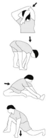
Start your warm up by walking on the spot for at least 3 minutes and then perform the following gymnastic exercises to the body for the training phase to prepare accordingly. The exercises do not overdo it and only as far run until a slight drag felt. This position will hold a while.
natural_image
Sequence of four sequential illustrations showing a person performing a stretching or kneeling movement (no text or symbols)Reach with your left hand behind your head to the right shoulder and pull with the right hand slightly to the left elbow. After 20sec. switch arm.
Bend forward as far forward as possible and let your legs almost stretched. Show it with your fingers in the direction of toe. 2 x 20sec.
Sit down with one leg stretched out on the floor and bend forward and try to reach the foot with your hands. 2 x 20sec.
Kneel in a wide lunge forward and support yourself with your hands on the floor. Press the pelvis down. Change after 20 sec leg.
MOTIVATION
The key to a successful program is regular training. You should set a fixed time and place for each day of training and prepare yourself mentally for the training. Only train when you are in the mood for it and always have your goalin view. With continuous training you will be able to see how you are progressing day by day and are approaching your personal training goal bit by bit.
Parts List – Spare Parts List AL 1 Order No. 1106(A), 11062
Technical data: Issue: 02.05.2022
• Magnetic brake system
• Aprox. 9 kg flywheel mass
- 8-gears manual resistance
• Hand pulse measurement
• horizontally (7cm) and vertically (21cm) adjustable saddle (quick release)
• Saddle and handlebar inclination adjustable
• Floor level compensation
- Touch Screen Computer showing at same time: speed, time, distance, approx calories and pulse frequency
- Input of limits for time, distance and approx calories
• Announcement of higher limits
- Load max. 150 kg (Body weight)
• Suitable for a height of 150-195cm
Space requirement approx. L 96, W 59, H 134 cm Items weight: 27kg
Exercise space approx: min. 2,5m²
Please contact us if any components are defective or missing, or if you need any spare parts or replacements in future.
This product is created only for private Home sports activity and not allowed to us in a commercial or professional area. Home Sport use class H/C

text_image
0 5 10 15 20 25 30 35 40 45 50 55 60 65 70 75 80 85 90 95 100 mm| Illus. No. | Designation Dimensions | mm | Quantity Attached to illustration No. | ET number 1106(A) | ET number 11062 |
| 1 Main Frame 1 33-9211-01-SI 33-1106101-SW | |||||
| 2 Screw | M4x12 2 17 39-10188 39-10188 | ||||
| 3 | Connection cable | 1 | 16+17 | 36-9211-07-BT | |
| 4 | Pulse unit with wire | 2 | 7 | 36-9211-08-BT | |
| 5 Screw | M5x50 1 11 39-10406 39-10406 | ||||
| 6 | Curved washer | 5//20 | 1 | 5 | 39-10111-VC |
| 7 | Handlebar | 1 | 12 | 33-9211-02-SI | |
| 8 Washer | 2 25+26 | 39-10520 39-10520 | |||
| 9 | Bushing | 1 | 25 | 36-9613209-BT | |
| 10 | Handle cover | 1 | 7 | 36-9211-09-BT | |
| 11 | Tension control | 1 | 12 | 36-9211-10-BT | |
| 12 | Handlebar post | 1 | 1 | 33-9211-03-SI | |
| 13 | Curved washer | 8//19 | 8 | 14+28 | 39-9966-CR |
| 14 | Screw | M8x16 | 4 | 12 | 39-9886-CR |
| 15 | Tension wire | 1 | 11+48 | 36-9211-11-BT | |
| 16 | Sensor wire | 1 | 3 | 36-9211-12-BT | |
| 17 | Computer | 1 | 12 | 36-1106203-BT | |
| 18 L | End cap left | 1 | 20 | 36-9211-13-BT | |
| 18 R | End cap right | 1 | 20 | 36-1107-08-BT | |
| 19 | Cap nut | 4 | 28 | 39-9900-CR | |
| 20 | Front stabilizer | 1 | 1 | 33-9211-04-SI | |
| 21 L | Crank left | 9/16" | 1 | 41 | 33-1107-12-SI |
| 21 R | Crank right | 9/16" | 1 | 41 | 33-1107-13-SI |
| 22 L | Pedal left | 9/16" | 1 | 21L | 33-1107-14-BT |
| 22 R | Pedal right | 9/16" | 1 | 21R | 33-1107-15-BT |
| 23 | Small plastic cover | 2 | 21 | 36-9840-15-BT | |
| 24 | Bolt | M8x25 2 21 39-10455 39-10455 | |||
| 25 | Hand grip bolt | 1 | 12 | 36-9211-16-BT | |
| 26 | End cap with height adjustment | 2 | 27 | 36-9211-17-BT | |
| 27 | Rear stabilizer | 1 | 1 | 33-9211-05-SI | |
| 28 | Bolt | M8x75 | 4 | 20+27 | 39-10019-CR |
| 29 | Saddle post | 1 | 1+33 | 33-9211-06-SI | |
| 30 | Knob bolt | 1 | 1+29 | 36-9211-18-BT | |
| 31 | Knob | 1 | 33+39 | 36-9211-19-BT | |
| 32 | Washer | 10//20 | 1 | 31 | 39-9989-CR |
| 33 | Saddle slide | 1 | 29 | 33-9211-07-SI | |
| 34 | Saddle | 1 | 33 | 36-9211-20-BT | |
| 35 | End cap | 2 | 7 | 36-9211-21-BT | |
| 36 Foam | grip 2 7 36-9211-22-BT 36-9211-22-BT | ||||
| 37 Spring | washer for M8 8 14+28 39-9864-VC 39-9864-VC | ||||
| 38 Handlebar | support cover 1 12 36-1107-04-BT 36-1107204-BT | ||||
| 39 Fixed | bracket 1 29+33 33-9211-08-SI 33-9211-08-SI | ||||
| 40 Square | end cap | 2 33 36-9211-23-BT 36-9211-23-BT | |||
| 41 | Axle | 1 | 42+82 | 33-9211-09-SI | 33-9211-09-SI |
| 42 Belt | wheel | 1 41 36-9211-24-BT 36-9211-24-BT | |||
| 43 | Belt | 430 PJ6 | 1 | 42+68 | 36-9211-25-BT |
| 44 | Bolt | M6x15 | 2 | 47 | 39-10120-SW |
| 45 | Spring washer | for M6 | 2 | 44 | 39-9865-SW |
| 46 | Spring bushing | C12 | 2 | 44 | 36-9111-39-BT |
| 47 Magnetic | bracket axle | 1 48 36-9211-26-BT 36-9211-26-BT | |||
| 48 | Magnetic bracket | 1 | 47+49 | 33-9211-12-SI | |
| 49 | Spring | 1 | 1+48 | 36-9211-27-BT | |
| 50 | Bolt | M6x35 | 1 | 1+48 | 39-10306 |
| 51 Nut | M6 | 1 50 39-9861-VZ 39-9861-VZ | |||
| 52 | Spring washer | for M10 | 2 | 57 | 39-9995 |
| 53 Bearing | 2 57 36-9211-36-BT 36-9211-36-BT | ||||
| 54 Idler wheel | 1 53 36-9211-28-BT 36-9211-28-BT | ||||
| 55 Bushing | 1 56 36-9211-14-BT 36-9211-14-BT | ||||
| 56 | Screw | M8x20 | 1 | 57 | 39-10095-CR |
| 57 Idler wheel bracket | 1 1 33-9211-11-SI | 33-9211-11-SI | |||
| 58 | Spring | 1 | 1+57 | 36-9211-37-BT | |
| 59 Nylon nut | M10 | 1 57 39-9981 | 39-9981 | ||
| 60 Axle nut | 2 69 39-9820-SW | 39-9820-SW | |||
| 61 | Screw | M6x40 | 2 | 1+69 | 39-10000 |
| 62 | U-piece | 2 | 61 | 36-9713-55-BT | |
| 63 Nut | M6 | 2 61 39-9861-VZ 39-9861-VZ | |||
| 64 Nut | 2 69 39-9820 | 39-9820 | |||
| 65 Bushing | 1 69 36-9211-15-BT 36-9211-15-BT | ||||
| 66 | Small pulley | 1 | 69 | 36-9211-38-BT | |
| 67 | Bearing | 6000Z | 2 | 68+69 | 39-9998 |
| 68 Flywheel | 1 67 33-9211-12-SI | 33-9211-12-SI | |||
| 69 Flywheel axle | 1 67 33-9211-13-SI | 33-9211-13-SI | |||
| 70 | Screw | 3,5x20 | 9 | 79 | 39-9909-SW |
| 71 | Screw | 3x10 | 12 | 20+27+72 | 39-10127-SW |
| 72 Round cover | 2 79 36-1107-05-BT 36-1107206-BT | ||||
| 74 | Washer | 2 | 44 | 39-10013-VC | |
| 75 Rubber ring | 1 1 36-9211-31-BT 36-9211-31-BT | ||||
| 76 | Nylon nut | M8 | 4 | 56+78 | 39-9918-CR |
| 77 | Wave washer | 17//22 | 1 | 41 | 36-9918-22-BT |
| 78 | Bolt | M8x16 | 3 | 41+42 | 39-9823-SW |
| 79 L | Chain cover left | 1 | 1+79R | 36-1106-11-BT | |
| 79 R | Chain cover right | 1 | 1+79L | 36-1106-12-BT | |
| 80 | Top cover | 1 | 79 | 36-1107-06-BT | |
| 81 | C-clip | C17 | 2 | 41 | 36-9805-32-BT |
| 82 | Bearing | 6203ZZ | 2 | 1+41 | 39-9947 |
| 83 | Washer | 4//10 | 2 | 2 | 39-10510 |
| 84 | Bolt | 3x10 | 2 | 85 | 39-10127-SW |
| 85 Rubber cover on chain cover | 1 80 36-9211-39-BT 36-9211-39-BT | ||||
| 86 Saddle bushing | 1 1 36-9211-40-BT 36-9211-40-BT | ||||
| 87 | Sensor holder | 1 | 1+16 | 36-9103-18-BT | |
| 88 Tool set | 36-9211-34-BT 36-9211-34-BT | ||||
| 89 Assembly and exercise instruction | 36-1106-14-BT 36-1106-14-BT | ||||
text_image
Technical diagram of a helicopter with numbered components and labeled partsEtape n° 2:
text_image
Technical diagram of a mechanical device with labeled parts and directional arrows indicating motion or assembly.text_image
Technical diagram of a stationary exercise bike with numbered parts and an inset close-up view highlighting mechanical components.text_image
Technical diagram of a stationary exercise bike with numbered components for identificationEtape n°6:
Contrôle
natural_image
Line drawing of a stationary exercise bike with adjustable arms and wheels (no text or symbols)Monter, utiliser & descendre
Transport de la machine:
natural_image
Diagram of a mechanical device with a lever and adjustment arrow, no text or symbols presentAttention:
text_image
Technical diagram of a helicopter with numbered components and labeled partsStap 2:
Montage van de pedalen (22L+22R)
text_image
Technical diagram of a helicopter with labeled parts and directional arrows indicating rotation or movement.text_image
Technical diagram of a stationary exercise bike with numbered parts and an inset close-up view highlighting key components.text_image
Technical diagram of a stationary exercise bike with numbered components for identificationStap 6: Controle:
natural_image
Line drawing of a stationary exercise bike with adjustable arms and wheels (no text or symbols)natural_image
Line drawing of a mechanical device with a lever and handle, no text or symbols presentBelangrijk:
Competitie - Zone: Prestaties / Competitie Training
02: Training hartslagberekening
natural_image
Sequence of four sequential illustrations showing a person performing a stretching or kneeling movement (no text or symbols)text_image
Technical diagram of a helicopter with numbered components and labeled partstext_image
Technical diagram of a helicopter with labeled parts and directional arrows indicating motion or assembly.text_image
Technical diagram of a stationary exercise bike with numbered parts and labeled connectorstext_image
Technical diagram of a stationary exercise bike with numbered components for identificationШаг 6: Контроль
natural_image
Line drawing of a stationary exercise bike with adjustable arms and wheels (no text or symbols)natural_image
Line drawing of a mechanical device with a lever and base, showing motion direction (no text or symbols)Важно:
text_image
Technical diagram of a mechanical device with numbered components and labeled partstext_image
Technical diagram of a stationary exercise machine with labeled components and rotation indicatorsKrok 3:
text_image
Technical diagram of a stationary exercise bike with numbered parts for identificationtext_image
Technical diagram of a stationary exercise bike with numbered components for identificationKrok 6: Kontrola
natural_image
Line drawing of a stationary exercise bike with adjustable arms and wheels (no text or symbols)Používání prístroje
Přeprava přístroje:
natural_image
Line drawing of a mechanical device with a lever and base, showing motion direction (no text or symbols)Důležité:
natural_image
Sequence of four sequential illustrations showing a person performing a stretching or kneeling movement (no text or symbols)text_image
Technical diagram of a helicopter with numbered components and labeled partstext_image
Technical diagram of a stationary exercise machine with labeled components and rotation indicatorstext_image
Technical diagram of a stationary exercise bike with numbered parts for identificationtext_image
Technical diagram of a stationary exercise bike with numbered components for identificationKrok 6: Sprawdzenie
natural_image
Line drawing of a stationary exercise bike with adjustable arms and wheels (no text or symbols)natural_image
Line drawing of a mechanical lever with a fulcrum and lever handle (no text or symbols)Ważne:
natural_image
Sequence of four sequential illustrations showing a person performing a stretching or kneeling movement (no text or symbols)text_image
Exploded view diagram of a mechanical device with numbered components for identification© by Top-Sports Gilles GmbH
D-42551 Velbert (Germany)
Service: