TTK 800 - Humidifier TROTEC - Free user manual and instructions
Find the device manual for free TTK 800 TROTEC in PDF.



User questions about TTK 800 TROTEC
0 question about this device. Answer the ones you know or ask your own.
Ask a new question about this device
Download the instructions for your Humidifier in PDF format for free! Find your manual TTK 800 - TROTEC and take your electronic device back in hand. On this page are published all the documents necessary for the use of your device. TTK 800 by TROTEC.
USER MANUAL TTK 800 TROTEC
Notes regarding the operating manual B-01
Information about the device. B-02
Safety B-06
Transport. B-07
Operation. B-08
Errors and faults B-11
Maintenance. B-12
Disposal. B-17
Declaration of conformity. B-17
Notes regarding the operating manual
Symbols

Hazardous electric current!
Warns about hazards from electric current which can lead to injuries or even death.

Danger!
Wards of a hazard which can lead to personal injury.

Caution!
Warns of a hazard which can lead to damage to property.
Legal notice
This release replaces all previous releases. No part of this publication may be reproduced without written permission. The same applies for electronically processing, duplicating or spreading the publication. Subject to technical changes. All rights reserved. Trademarks are used without guarantee that they may be used freely and primarily following the spelling of the manufacturer. The product names used are registered and should be treated appropriately. The delivered product may vary from product images. This document was produced with all due care. We accept no liability whatsoever for mistakes or omissions. © TROTEC
Warranty
The warranty is for 12 months. Damages caused by incorrect use by untrained people or commissioning by unauthorised people are excluded from the warranty.
The device complies with the fundamental health and safety requirements of the applicable EU regulations and was tested at the factory for perfect functionality multiple times. However, if faults in the functionality occur and cannot be remedied with the information in the chapter "Errors and faults", please get in touch with your dealer or distributor. When making a warranty claim, supply the device number (see nameplate). The invoice acts as warranty certificate. When manufacturer's instructions or legal regulations have not been followed, or after unauthorised changes to the device are made, the manufacturer is not responsible for the resulting damages. Changes to the device or unauthorised replacement of individual parts can drastically impact the electrical safety of this product and leads to the forfeiture of the warranty. Liability does not extend to damages to people or property caused by the device being used other than as described in the instructions in this operating manual. Subject to changes to technical design and model changes as part of constant development and product improvement without prior notice.
No liability is accepted for damages resulting from improper use. In such cases, entitlements to a warranty are also forfeited.
The current version of the operating manual can be found at: www.trotec.de.
Information about the device
Description of the device
This device uses the principle of condensation to automatically dehumidify rooms. To do so, the device can be used in continuous operation.
The fan sucks damp room air through the air inlet (2), the air filter (3), the evaporator and to the condenser located behind it. The air is cooled at the cold evaporator until it is below the dew point. Water vapour contained in the room air precipitates on the evaporator fins as either condensation or frost. The dehumidified, cooled air is warmed again and blown out from the air outlet (6). The drier air which is prepared in this way mixes with the air in the room. The humidity in the room where the device is positioned is reduced as air constantly circulates through the device. Depending on the air temperature and the relative humidity, the condensed water either drops continuously or only during the defrost phase into the condensation tray. The condensation is fed through a pressure-resistant pipe connection and out of the device at a preinstalled condensation drain hose (5).
The condensed water can be diverted by retrofitting a condensation pump.
For easy transport, the device is fitted with a bar handle (1) and wheels (4). In working position, the device sits tilted on the stand bar (7).
The device can reduce the relative humidity of a room by up to approx. 35% . Because of the heat radiation which is tied up in operation, the room temperature can rise by approx. 1 - 3^
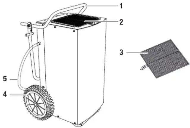
Device depiction and operating elements
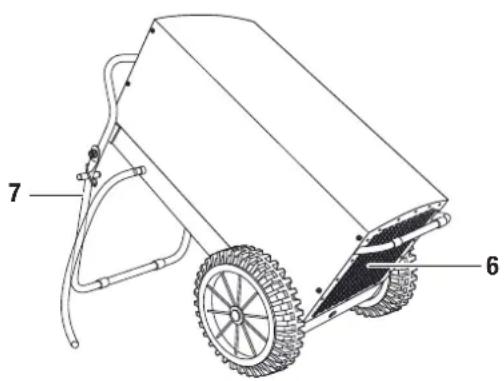
| No. | Operating element | |
| 1 | bar | handle |
| 2 | air | inlet |
| 3 | air | filter |
| 4 | 4 | w h e e l s |
| 5 | condensation drain hose | |
| 6 | air outlet | |
| 7 | stand bar | |
Scope of supply (standard)
- construction dryer TTK 800
- air filter
- condensation drain hose
operating manual
Optional accessories
- air filter
- humidistat
- condensation pump
energy cost gauge
Technical data
| Parameters Values | |
| Model TTK 800 | |
| Dehumidifying capacity, max. 150 l / 24 h | |
| Dehumidifying capacity (20 °C / 60 % relative humidity) 55 l / 24 h | |
| Suitable for room dimensions up to: construction drying or clearing water damages maintaining dryness | 800 m³1600 m³ |
| Operating temperature 0-40 °C | |
| Working range for relative humidity 35-100 % | |
| Volume of airflow, max. 940 m³/h | |
| Electric connection 230 V / 50 Hz / 9.5 A | |
| Power consumption, max. 2.4 kW | |
| Power consumption, average 1.7 kW | |
| Fuse (home) | 16 A |
| Compressor | Rotary |
| Refrigerant | R407c |
| Amount of refrigerant | 1.05 kg |
| Weight | 70 kg |
| Dimensions (HxDxW) | 1020 x 585 x 630 mm |
| Minimum distance from walls of other objects | A: Above: 50 cmB: Behind: 50 cmC: Side: 50 cmD: Front: 50 cm |
| Sound pressure level LpA (3 m; complies with DIN 45635-01-KL3) | 60 dB(A) |
Power consumption
The device's power consumption depends on the current room temperature and relative humidity.
Multiply the operating hours (see operating hours counter in the chapter "Operating elements") by a consumption value of one kilowatt per hour to determine the approximate power consumption.
To determine the precise power consumption, a separate energy cost gauge can be set between the construction dryer and the power source. Contact TROTEC ^® customer service if you want this alternative version.
Cooling circuit diagram
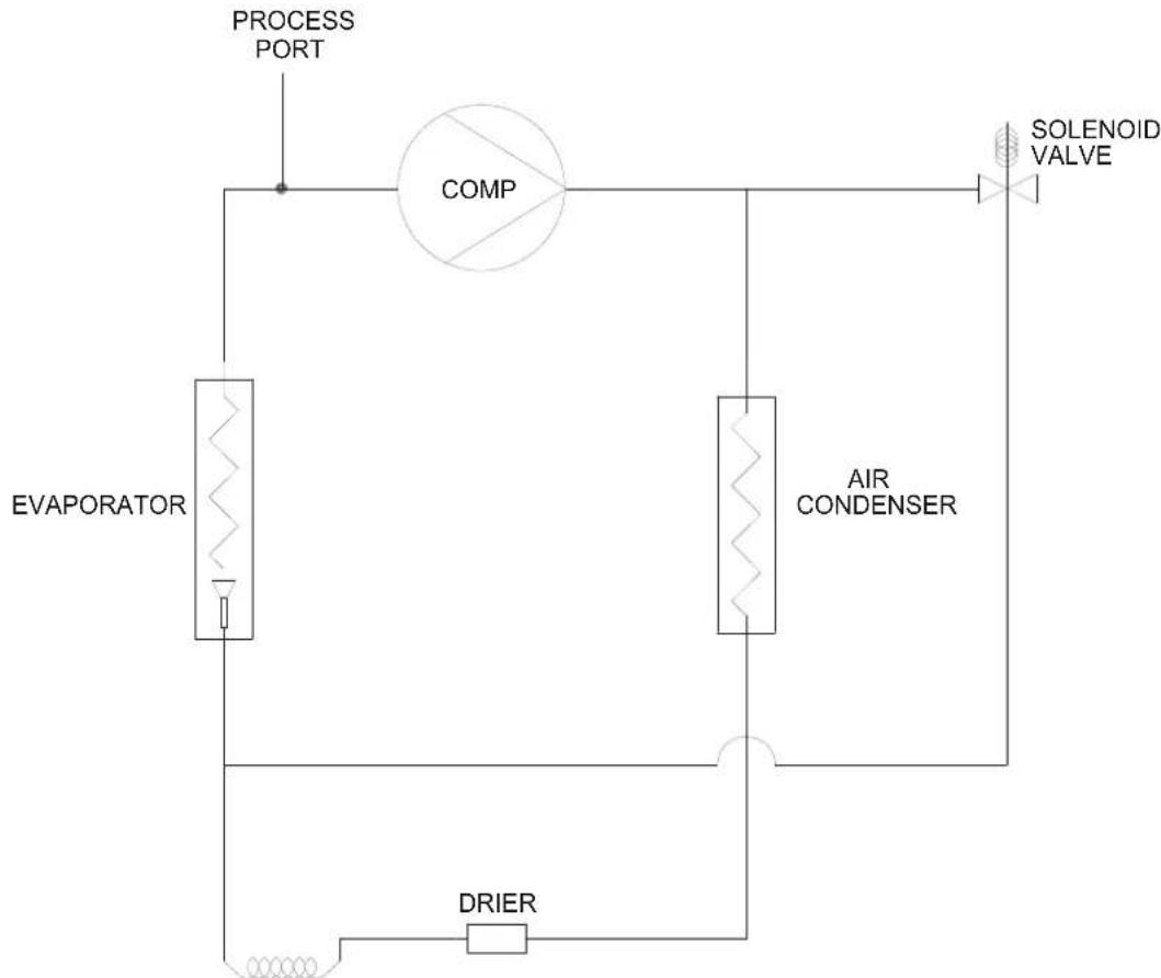
Circuit diagram
| 1 | INITIAL ISSUE | 1394 | KV | ISO'01'16 |
| 66.07 | APPD DATE | |||
| CHROMOSCHARGE | ||||
Safety
Read this manual carefully before starting or using the device. Store the manual near the device or its site of use!
- Do not use the device in potentially explosive rooms.
- Do not use the device in atmospheres containing oil, sulphur, chlorine, acid or salt.
- Do not operate the device in rooms which are pressurised with acetone, undiluted acids or solvents.
- Set the device in an upright and stable position.
- Do not expose the device to directly squirting water during operation.
- Ensure that the air inlet and outlet are not obstructed.
- Ensure that the side of the device where the air inlet is found is kept free of dirt and loose objects.
- Never insert objects or limbs into the device.
- Do not cover or transport the device during operation.
- Do not sit on the device.
- Ensure that all electric cables outside of the device are protected from damage (e.g. from animals).
- Only use extensions to the electric cable which are appropriate to the device power consumption, the length of its cable and its use. Avoid electrical overload.
- Only transport the device in an upright position with an emptied condensation pump and tray.
- Dispose of the collected condensation. Do not drink it. There is a risk of infection!
Intended use
Only use the device TTK 800 as a mobile industrial dryer for drying and dehumidifying room air, while adhering to and following the technical data.
Intended use encapsulates:
- drying and dehumidifying:
production plants, underground rooms
- store rooms, archives, laboratories
- rooms and areas after water damages from burst pipes or flooding
- maintaining the dryness of:
instruments, devices and files
- electric control devices, boiler plants, turbines and pipe systems in power plants
- moisture-sensitive loads etc.
Improper use
Do not place the device on flooded ground. Do not use the device outdoors. Do not lay any objects, e.g. wet clothing, on the device for drying. Any changes, modifications or alterations to the device which have not been authorised by TROTEC are forbidden.
Personnel qualifications
People who use this device must:
- be aware of the dangers that occur when working with electric devices in damp areas.
- take measures to protect themselves from direct contact with live parts.
have read and understood the operating manual, especially the "Safety" chapter.
Maintenance tasks at the electrical equipment or the air-conditioning technology must only be carried out by specialist companies for cooling and air-conditioning or by TROTEC.
Residual risks

Hazardous electric current!
Work on the electrical components must only be carried out by an authorised specialist company!

Hazardous electric current!
Before any work on the device, remove the mains plug from the mains socket!

Caution!
To avoid damages to the device, never operate the device without an air filter inserted!

Danger!
Dangers can occur at the device when it is used by untrained people in an unprofessional or improper way! Observe the personnel qualifications!

Danger!
A toppling device can cause you injuries! Only slightly tilt the device and move it carefully. If necessary, ask another person to help. For longer distances, transport the device with a fork lift or elevating truck. Never stand below the device when suspended in the air.
Behaviour in the event of an emergency
- Disconnect the device from the mains power in an emergency.
- Do not reconnect a defective device to the mains power.
Transport
To make the device easier to transport, it is fitted with wheels and a bar handle. If necessary, transport the device with the help of another person. To lift the device, use a fork lift or an elevating truck.
Before transporting the device, proceed as follows:
- Switch off the device at the mains switch (see chapter "Operating elements").
- Remove the mains plug from the mains socket. Do not use the power cable to drag the device!
- Empty the condensation drain hose or the condensation pump (optional). Check for dripping condensation.
- If the device is standing in working position, hold the bar handle with two hands and carefully lift the device into an upright position.
- Ensure that the stand bar is folded inwards and secured with both safety rings (see chapter "Positioning").
- Hold the bar handle in both hands again and tilt the device lightly.
- Transport the device on its wheels.
After transporting the device, proceed as follows:
- Firstly, set the device in an upright position after transport.
- Move the device to its working position (see chapter "Positioning").
- Ensure that the rubber supporting surface of the stand bar lies flat on the floor. The rubber supporting surface of the stand bar prevents the device from rolling away.
Storage
When out of use, store the device as follows:
d r y,
with a roof overhead,
- in an upright position where it is protected from dust and direct sunlight,
- with a plastic cover to protect it from invasive dust, if necessary.
- The storage temperature is the same as the range given for the operating temperature in the chapter "Technical data".
Operation
After being switched on, the device operates fully automatically.
- Avoid open doors and windows.
Positioning
When positioning the device, observe the minimum distance from walls of other objects as described in chapter "Technical data".

- Set the device in a stable position. Only use the device in its working position.
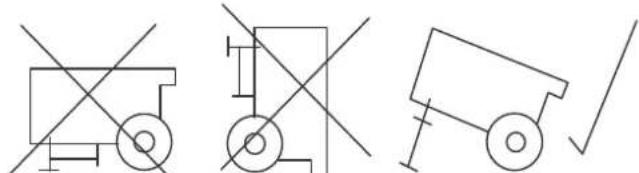
- When positioning the device, keep a sufficient distance away from sources of heat.
- If possible, set the device in the middle of a room. If using multiple devices, ensure that the spaces between devices is equal.
- When positioning the device in wet areas, secure the device locally with an RCD (Residual Current protective Device) which complies with the appropriate regulations.
- Ensure that extension cords are completely unrolled.
- Ensure that power supply's voltage and current comply with the specifications on the device's nameplate.
- When using a generator, ensure that the generator supplies at least 4kW of power (device starting current can exceed the nominal current by four or five times. Also note this fact when using several devices at one generator).
Position the device as follows:
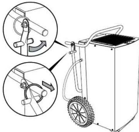
A.
B.
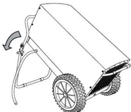
Notes regarding the dehumidifying capacity
The dehumidifying capacity depends on:
- the spatial composition of the room
- the room temperature
the relative humidity
The higher the room temperature and relative humidity, the higher the dehumidifying capacity.
For using in living rooms, a relative humidity of approx. 50 - 60% is sufficient. In store rooms and archives, the humidity should not exceed approx. 50% .
Operating elements
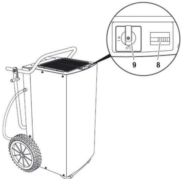
| No. | Operating element |
| 8 | Operating hours counter |
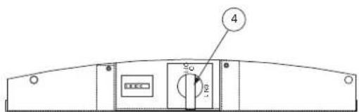
| 9 | M a i n s s w i t c h : "ON": Device is switched on. "OFF": Device is switched off. |
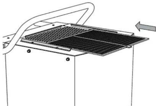
Start procedure Insert air filter
Positioning the condensation drain hose
Note:
The condensation drain hose is already installed when the device is delivered.
-
Ensure that the condensation drain hose is properly connected to the device and is free of damage.
-
Depending on use, position the end of the condensation drain hose as follows:
-
Position a sufficiently large container (at least 90 litres) beside the device and insert the hose end. Check the fill level of the container regularly.
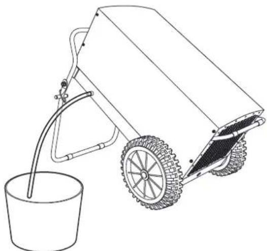
- Position the end of the condensation drain hose above a water drain. For larger distances, a longer hose of the same type can also be used.

-
The device can also be operated with a condensation pump. Contact TROTEC® customer service if you want this alternative version.
-
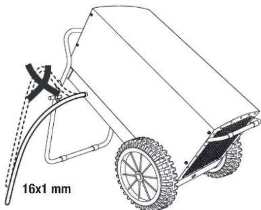
Ensure that the condensation drain hose always descends.
Switching on the device
- Ensure that the condensation drain hose (5) has been laid and connected properly. Do not create tripping hazards.
- Ensure that the condensation drain hose (5) is not bent or jammed and that there are no objects on the condensation drain hose (5).
- Ensure that the condensation can run off properly.
- Insert the mains plug into a properly secured mains power socket. Do not create tripping hazards.
- Empty any condensation from the device by pressing the button for draining residual water from the condensation pump (optional).
- Ensure that the device is standing stably in its working position.
- Switch on the device at the mains switch (9).
"Continuous" operation mode
In continuous operation mode, the device dehumidifies the air constantly, regardless of the humidity in the air.
"Humidistat" operation mode (optional)
The device can also be operated with a humidistat.
The humidistat switches the device on or off depending on the humidity.
If you choose to operate the device with an optional humidistat, set the desired humidity at the humidistat (see operating manual of the optional humidistat).
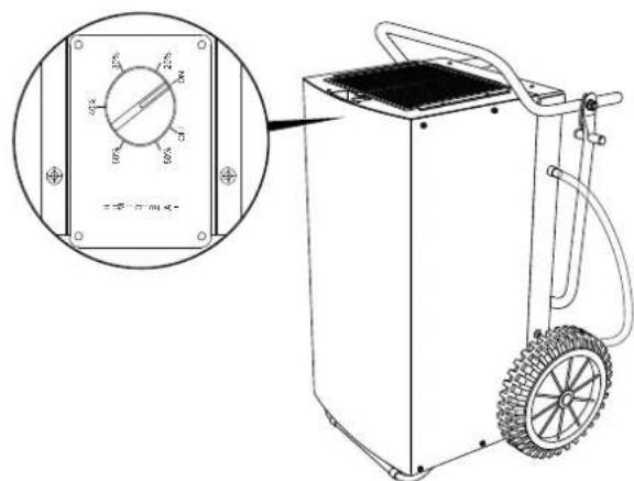
Automatic defrost
Depending on the air temperature and the relative humidity, the evaporator fins may become covered in frost. The hot gas automatic defrost which is installed in the device switches back on as needed. Dehumidify mode is briefly interrupted during defrosting.
Shut down procedure
- Switch off the device at the mains switch (9).
- Empty any condensation from the device by pressing the button for draining residual water from the condensation pump (optional).
- Do not touch the mains plug with wet or damp hands.
- Remove the mains plug from the mains socket.
- Remove the condensation drain hose (5) and any residual fluid from it.
- Clean the device, and especially the air filter, according to chapter "Maintenance".
- Store the device according to chapter "Storage".
Errors and faults
The accurate functionality of the device was tested during production a number of times. However, if functionality faults do occur, then check the device according to the following list.

Caution!
To prevent damages to the device and to prevent the fuse or motor protection switch from tripping, ensure the device is switched off and wait at least 5 minutes before switching the device back on.
The device does not start:
- Check the mains power (230 V/1~/50 Hz).
- Check the mains plug for damages.
- Check whether the mains switch (9) is in the "ON" position.
- Check the fuse (home).
- If you operate the device with a humidistat, check the desired humidity. The humidity in the room must be above the selected range. Reduce that the selected humidity.
- Have the electrics checked by a specialist company for cooling and air-conditioning or by TROTEC®.
The device runs but forms no condensation:
- Check the condensation drain hose is positioned correctly.
- Check that the condensation pump (optional) functions properly. Check for abnormal vibrations and sounds. Remove external dirt.
- Check the room temperature. Check the device's permissible working range complies with the technical data.
- Ensure that the relative humidity complies with the technical data.
- If you operate the device with a humidistat, check the desired humidity. The humidity in the room must be above the selected range. Reduce that the selected humidity.
- Check the air filter is not dirty. If necessary, clean or replace the air filter.
The device is loud or vibrates; condensation leaks:
- Check whether the device is standing upright and on an even surface.
The device gets very warm, is loud or is losing performance:
- Check the air inlets and air filter are not dirty. Remove external dirt.
- Check the inside of the device for dirt (see chapter "Maintenance"). Clean the inside of the device as described in the chapter "Cleaning the inside with compressed air".
Does your device still not operate correctly after these checks?
Bring the device to a specialist company for cooling and air-conditioning or to TROTEC® for repairs.
Maintenance
Maintenance intervals
Maintenance and care log
| Maintenance and care interval before every start | when neces- sary | at least every 2 weeks | at least every 4 weeks | at least every 6 months | at least annu- ally | |
| empty the condensation pump, condensation tray and/or construction dryer | X | |||||
| check air inlets and outlets for dirt and foreign objects and clean if necessary | X | X | X | |||
| visually check whether the inside of the device is dirty X X | ||||||
| clean the inside with compressed air X X | ||||||
| check air inlet grid and air filter for dirt and foreign objects and clean or replace if necessary | X | X | ||||
| replace air filter X | ||||||
| check for damages X | ||||||
| check attachment screws X X | ||||||
| carry out a test run X |
Device type: Device number:
| Maintenance and care interval | 1 | 2 | 3 | 4 | 5 | 6 | 7 | 8 | 9 | 10 | 11 | 12 | 13 | 14 | 15 | 16 |
| check air inlets and outlets for dirt and foreign objects and clean if necessary | ||||||||||||||||
| clean housing | ||||||||||||||||
| visually check whether the inside of the device is dirty | ||||||||||||||||
| clean the inside with compressed air | ||||||||||||||||
| check air inlet grid and air filter for dirt and foreign objects and clean or replace if necessary | ||||||||||||||||
| replace air filter | ||||||||||||||||
| check for damages | ||||||||||||||||
| check attachment screws | ||||||||||||||||
| carry out a test run | ||||||||||||||||
| Remarks: | ||||||||||||||||
| 1. Date: Signature: | 2. Date: Signature: | 3. Date: Signature: | 4. Date: Signature: |
| 5. Date: Signature: | 6. Date: Signature: | 7. Date: Signature: | 8. Date: Signature: |
| 9. Date: Signature: | 10. Date: Signature: | 11. Date: Signature: | 12. Date: Signature: |
| 13. Date: Signature: | 14. Date: Signature: | 15. Date: Signature: | 16. Date: Signature: |
Activities for before the start of maintenance
- Do not touch the mains plug with wet or damp hands.
- Before any work, detach the mains plug!
Maintenance tasks at the electrical equipment or the air-conditioning technology must only be carried out by specialist companies for cooling and air-conditioning or by TROTEC®.
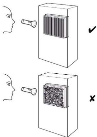
Visual check for dirt in the inside of the device
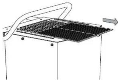
- Remove the air filter (see chapter "Cleaning the air inlets and the air filter").
- Shine a torch through the opening of the device.
- Check the inside of the device for dirt.
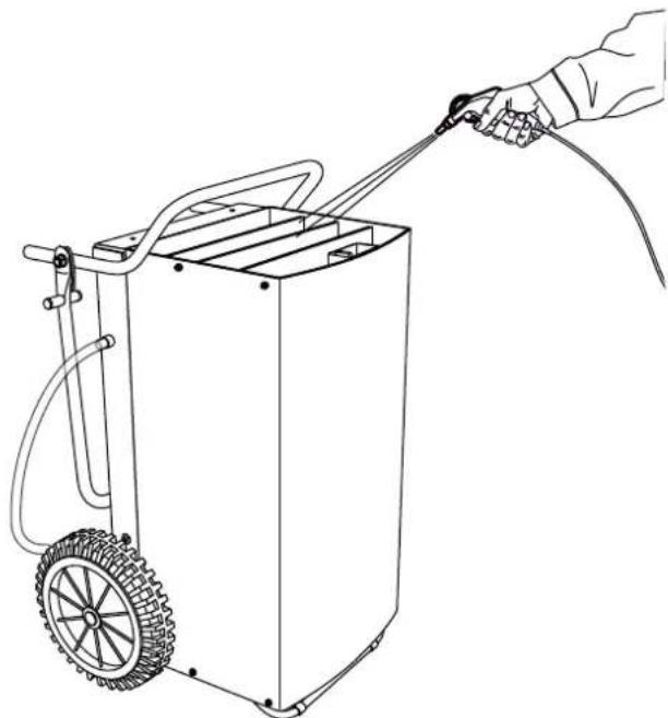
- If you find dirt, use a high pressure cleaner to clean the device according to "Cleaning the air inlets and the air filter".
- Put the air filter back in.
Cleaning the air inlets and the air filter
A.
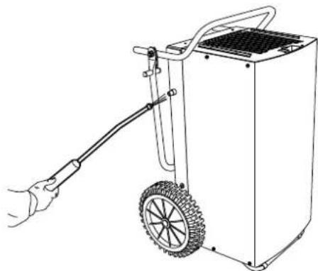
B.
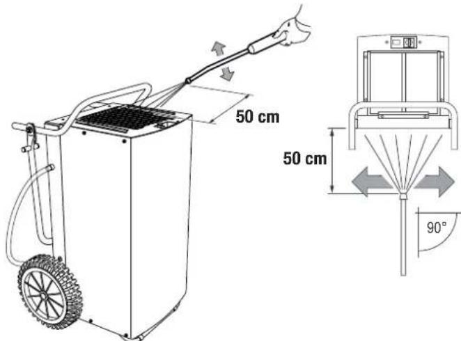
C.
D.
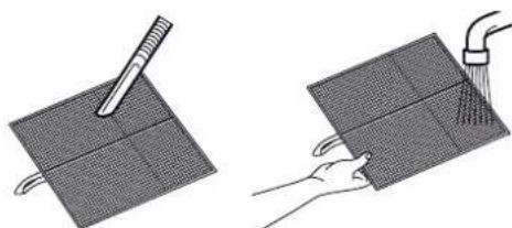

Caution!
After you have cleaned the device with a high pressure cleaner, check the air filter, which you have already removed, for damages. The corners and edges must not be rounded or misshaped.
Before reinserting the air filter, ensure that it is dry and is not damaged!
Read the chapter "Maintenance intervals" and replace the air filter punctually!
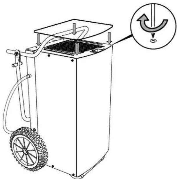
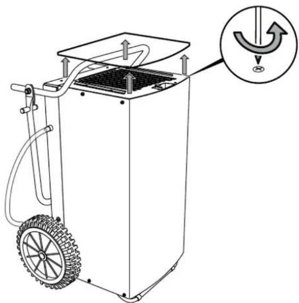
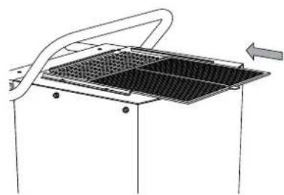
Cleaning the inside with compressed air
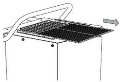
A.
D.
B.
E.
C.
Overview and list of spare parts Main components
Note!
The position numbers of the spare parts differ from those describing the positions of other parts mentioned in this operating manual.
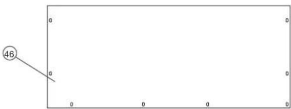

FIG 2 COMPLEXED MODELING (A) AND (B) FRETOSPECTRUM
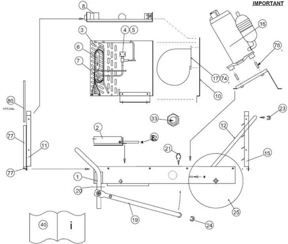
IMPORTANT
B.

GAS CHARGE 1.050kg
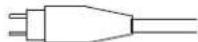

MAINS LEAD EUROPE
| No. Item number Spare part No. Item number Spare part | |||
| 1 SD512901 BTM casing assembly 22 7330000884 pipe insert bung | |||
| 2 SD364402 drip tray 23 7310000202 saddle foot | |||
| 3 7162000933 evaporator/condenser assembly 24 7310000201 saddle foot 25 mm tube | |||
| 4 7140001337 defrost valve | 25 7600001249 wheel | 330 0/D 30-58-133 | |
| 5 7420001338 solenoid coil | 27 7333000378 plug/lead assembly | ||
| 6 72200000195 | drier molecular sieve 1/4 x 1/4 | 33 | SP152150 M20 plastic gland back nut |
| 7 P524750 | capillary 0.102" OD x 0.060" ID x 55" | 40 | SD533252 user manual |
| 8 SA373504 electric box assembly 45 SD182554 refrigerant R407c | |||
| 10 SD521850 fan mounting panel 46 7242000173 top cover | |||
| 11 7242000174 inlet grill | 74 SP144250 | clip U nut no. 8 screw | |
| 15 SD509601 outlet grill | 77 SD512850 filter guide | ||
| 16 7161000931 rotary compressor 78 SD520852 spacer | 37 mm LG 10 mm O/D 8.20 mm I/D | ||
| 17 7150000932 centrifugal fan | |||
| 19 SD365450 lifting leg black | |||
| 20 SD365550 locking ring BLK 51-22-103 | |||
| 21 7242000169 spring clip |
List of spare parts - Electrical equipment
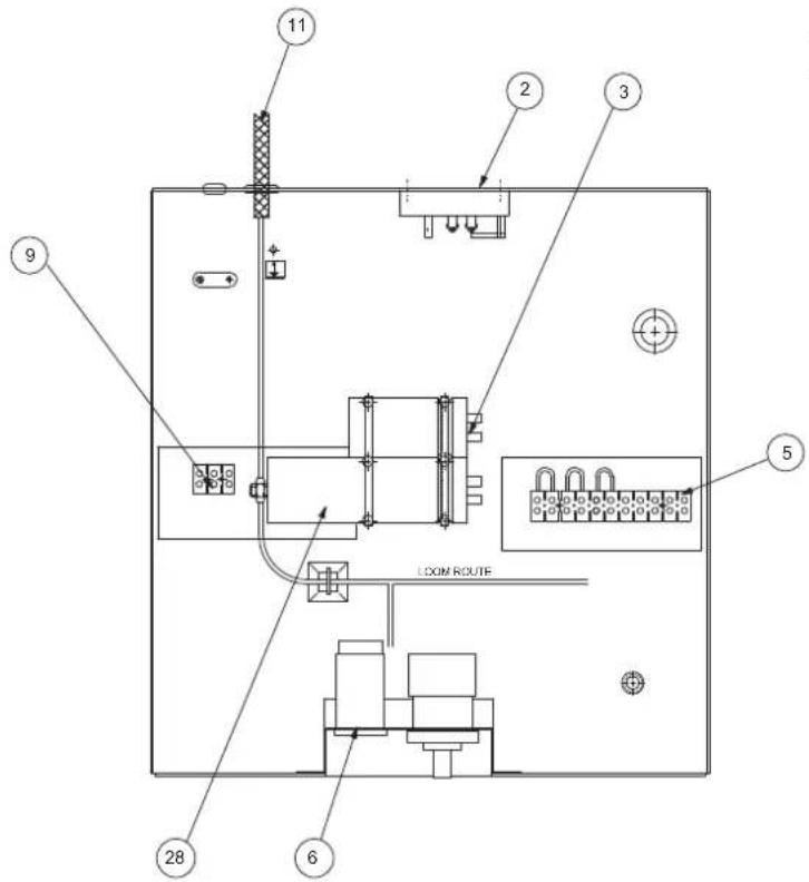
| No. Item number Spare part | |
| 2 7140000928 defrost stat | |
| 3 SD022550 capacitor 35 μF 440 V 50/60 Hz | |
| 4 7130000918 rotary switch 2 pole on/off | |
| 5 SAD98763 terminal block 11-way 10 A | |
| 6 7140000899 operating hours counter assembly | |
| 9 SA098762 terminal block 3-way 10 A | |
| 28 SD271250 capacitor 8 μF 500 V 50/60 Hz |
Note!
The position numbers of the spare parts differ from those describing the positions of other parts mentioned in this operating manual.
Disposal Declaration of conformity
In the European Union, electronic equipment must not be treated as domestic waste, but must be disposed of professionally in accordance with Directive 2002/96/EC of the European Parliament and Council of 27th
January 2003 concerning old electrical and electronic equipment. At the end of its life, please dispose of this instrument in a manner appropriate to the relevant legal requirements.
The device uses an environmentally friendly and ozone-neutral refrigerant (see chapter "Technical data"). Dispose of the refrigerant/oil mixture appropriately and according to the national regulations.
in accordance with the EC Low Voltage Directive 2006/95/EC and the EC Directive 2004/108/EC about electromagnetic compatibility.
Herewith, we declare that the condenser dryer TTK 800 was developed, constructed and produced in compliance with the named EC directives.
Applied harmonised standards:
IEC 60335-1:2001/A2:2006
IEC 60335-2-40:2002/A1:2005
IEC 62233:2005
The marking is found on the device nameplate.
Manufacturer:
Furniture (standard)
27140000928 defrost stat
3 SD022550 capacitor 35 μF 440 V 50/60 Hz
47130000918 rotary switch 2 pole on/off
5 SAD98763 terminal block 11-way 10 A
67140000899 operating hours counter assembly
9 SA08762 terminal block 3-way 10 A
28 SD271250 capacitor 8 μF 500 V 50/60 Hz