
TTR 250 Ex - Humidifier TROTEC - Free user manual and instructions
Find the device manual for free TTR 250 Ex TROTEC in PDF.


| Product Type | Air Dehumidifier (Adsorption) |
| Brand | Trotec |
| Model | TTR 250 Ex |
| Technology | Silica gel rotor |
| ATEX Classification | II 3D Ex c T240°C (Zone 22) |
| Operating Ambient Temperature | -20°C to +40°C |
| Max Process Air Inlet Temperature | +40°C |
| Min Regeneration Air Inlet Temperature | -15°C |
| Filter Type | G4 (Z-line, fiber mat in steel frame) |
| Housing Material | Stainless steel 1.4301 (SS304) |
| Heater Type | Self-regulating PTC thermistor (surface temp. ~240°C) |
| Fan Type | Centrifugal with AC external rotor motor |
| Rotor Drive | Geared motor with synchronous pulley and belt |
| Rotor Bearing | Maintenance-free slide bearing bushings |
| Maintenance Interval | Every 6 months or 4,000 operating hours |
| Filter Replacement | Weekly or as needed |
| Rotor Cleaning | With vinegar solution (pH 4–6), rinse with water |
| Safety Features | ATEX compliant, restart protection, functional monitoring |
| Dry Air Outlet Temperature (Normal) | 25°C to 40°C |
| Wet Air Outlet Temperature (Normal) | 30°C to 50°C |
Frequently Asked Questions - TTR 250 Ex TROTEC
User questions about TTR 250 Ex TROTEC
0 question about this device. Answer the ones you know or ask your own.
Ask a new question about this device
Download the instructions for your Humidifier in PDF format for free! Find your manual TTR 250 Ex - TROTEC and take your electronic device back in hand. On this page are published all the documents necessary for the use of your device. TTR 250 Ex by TROTEC.
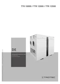
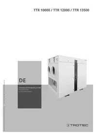
USER MANUAL TTR 250 Ex TROTEC
INHALT
Funktionsprinzip
- General Maintenance ....B - 07
- Filter Replacement ...... B - 08
-
Rotor Cleaning B - 08
-
Detrimental Effects on Silicagel Rotors . . B - 08
- Troubleshooting.....B - 10
- Declaration ....
- Technical Appendix ....
01. SAFETY INSTRUCTIONS
Observe the notes in the Operating Instructions
- The basic condition for the safe handling and trouble-free operation of this air dehumidifier is the knowledge of basic indications and regulations applicable to safety.
- The present Operating Instructions include the most important indications required for the safe operation of the air dehumidifier.
- These Operating Instructions and especially the indications on safety must be observed by all persons working on the air dehumidifier.
- The rules and regulations for the prevention of accidents applicable on site must be observed in addition to this.
Obligations of the Operator
The operator has the obligation to allow work on the air dehumidifier only for persons who:
- Are well acquainted with the basic regulations on occupational safety and on the prevention of accidents and who have been familiarised with the operation of the air dehumidifier
- Have and respectively proved to have the essential expert knowledge
- Have read and understood the Safety and the warning notices included in these operating instructions.
- The operator has to check the observance of the safety regulations by the personnel on a regular basis.
Obligations of the Personnel
All persons who are charged with performing work on the air dehumidifier must assume the following obligations before taking up work:
- Observe the basic regulations on occupational safety and accident prevention.
- Read the Section on Safety and the warning notices included in these Operating Instructions.
Organisational Measures
- The operator must provide the required personal protection equipment.
- All existing safety appliances must be checked on a regular basis.
Informal Safety Measures
- The Operating Instructions must always be kept at the place where the air dehumidifier is operated.
- General and local regulations for accident prevention and environmental protection must be provided and observed in addition to the Operating Instructions.
- All notes on safety and hazards on the air dehumidifier must be kept in a legible condition.
Intended Use
The air dehumidifier is designed only for dehumidification of atmospheric air. Any other use or any use in addition to this shall be deemed to be not intended. TROTEC GmbH & Co. KG will not assume any liability for damages resulting from such unintended use.
The air dehumidifier must not be arranged in any liquids and respectively must not intake any liquids (e.g. filled tanks, flooded areas).
The operation in and/or with combustible atmosphere is permitted only for units labelled according to the directive 94/9/EG (Atex 95). The operator is obligated to examine the usability of the airdehumidifier in accordance to the directive 1999/92/EC (Atex 137)!
The intended use also includes:
- The observance of all indications given in the Operating Instructions and
- The due performance of inspection and maintenance activities.
Hazards during the Operation of the Air Dehumidifier
The air dehumidifier has been manufactured according to the state-of-the-art and the generally accepted rules of safety engineering. The air dehumidifier has to be used only:
- For the intended purpose
- In a perfectly safe condition.
- Faults which may affect safety must be eliminated immediately.
Safety Guards
- All protective devices must be installed as appropriate and be in an operative condition before starting the air dehumidifier.
- Protective devices may only be removed:
a) after shutdown and
b) protection against restarting.
- The operator must install the protective devices himself in accordance with regulations if the device is supplied in individual parts.
Hazards Caused by Electrical Energy
- Work on the power supply may only be carried out by professional electricians.
- Check the air dehumidifier's electrical equipment on a regular basis. Eliminate any loose connections and damaged cables immediately.
- The switch room must always be locked. Access is only allowed to authorised personnel using adequate tools.
- If work on any charged parts is required, a second person must be present to cut power supply if necessary in case of emergency.
Maintenance, Upkeep and Troubleshooting
- Perform prescribed setting, maintenance and inspection activities when due.
- Inform the operating personnel before starting any maintenance and upkeep work.
- All pre and post equipment is to be protected against restarting.
- Disconnect power on the air dehumidifier and protect the main switch against unintentional restarting before starting any maintenance, inspection or repair activity.
- Place a danger sign to prevent restart.
- Check loosened screw connections for solid fit.
- Check the function of safety appliances at the end of the maintenance activities..
Structural Alterations to the Air Dehumidifier
- No alteration, addition or remodelling of the air de-humidifier is allowed without authorisation by the manufacturer. This also applies to welded structural parts.
- Use only original spare and wearing parts.
Air Dehumidifier Cleaning and Waste Disposal
- All substances and materials used must be handled and disposed off adequately. This applies especially to work on the lubrication system and to cleaning with solvents.
Warranty and Liability
Our "General Conditions of Sale and Delivery" will be applied in principle. These Conditions will be made available to the operator by the latest when concluding the contract. Claims under a warranty or under a liability for injury to persons or damage to property will be ruled out if such claims are due to one or more of the following causes:
- Misuse of the air dehumidifier;
- Inappropriate mounting, start-up, operation and maintenance of the air dehumidifier;
- Operation with defective safety appliances, or with safety and protective devices which are not mounted adequately and orderly, or not operative;
- Non-compliance with the indications given in the Operating Instructions on the transportation, storage, mounting, start-up, operation and maintenance of the air dehumidifier;
- Unauthorised structural alterations;
- Unauthorised alteration to the technical design;
- Defective monitoring of components subject to wear and tear;
• Unprofessional performed repairs - Catastrophes caused by foreign objects or force majeure.
Special indications on safety
Units intended for use in explosion-proof areas are liable to increased safety requirements according to directive 94/9/EG. The terms of this directive are carefully followed by Trotec. The units are designed for operation in “Zone 22” (according to directive 1999/92/EC).
For durably safe operation in this zone the following information is to be observed strictly:

- The Atex labelling gives information on the maximum surface temperature (ts) . Resulting from this the minimum temperatures for a safe operation with dusts are:
a) Smouldering temperature tsm > ts + 75°C
b) Ignition temperature ti > 1,5 × ts
In case of decreasing these temperatures there could be danger of smouldering fire (smouldering temperature) or dust explosion (ignition temperature).
- The effects specified above are increased by damaged intake-air filters and contaminated surfaces inside the unit. Therefore the intervals for maintenance and filter replacement must be kept.
- Any charged connection must not be disconnectable or disconnected anytime. There is danger of electric arc and therefore dust explosion
- The Compensation of electric potential must be assured.
- Subsequent changes on the electrical equipment are generally not permitted.
- To keep reliability, wearing parts and damaged components have to be replaced immediately by original spare parts or by spare parts under written release by Trotec.
02. GENERAL DESCRIPTION
Utilisation
Air dehumidifiers working on the principle of adsorption are used in process engineering, air conditioning and for air dehumidification in production and storage rooms containing products and facilities requiring a particularly low air humidity.
Adsorption technology attains lower dew points and operationally reliable dehumidification at intake air temperatures <0°C . At these points, dehumidifiers with cooling technology cannot reach this performance for physical reasons any longer. In addition, air dehumidifiers work by far more efficiently under these operating conditions.
Operating Conditions
Trotec air dehumidifiers are usually designed for conditions of inlet air at +20°C/ 60%r.h. With increasing relative humidity of the process-air and/or increasing relative humidity of the regeneration-air the dehumidifying performance will fade.
A) The operation of the dehumidifier is allowed for ambient temperatures between -20°C and +40°C!
B) The inlet process-air temperature has to be lower than +40°C and the regeneration-air temperature higher than -15°C!
C) The intake air must not contain any condensate!
D) Air dehumidifiers must not be positioned in any liquids and respectively must not intake any liquids (e.g. filled tanks, flooded areas).
E) The operation in and/or with combustible atmosphere is permitted only for units labelled according to the directive 94/9/EC (Atex 95). The operator is obligated to examine the usability of the air-dehumidifier in accordance with the directive 1999/92/EC (Atex 137)!
F) In the case of admission with contaminated air the "Detrimental Effects on Silicagel Rotors" have to be observed strictly!

Functional Principle
During rotation the rotor (1) passes three sections (process (A), regeneration (D) and purge (W)). A fan (2) blows the inlet air into the unit. The larger process airflow (P) is dehumidified in the process section (=adsorption). The smaller regeneration airflow (R) is pre-heated in the purge section while the rotor material is cooled down at the same time. Then the regeneration air flow passes the heater (4) and afterwards the regeneration section (D) where the water adsorbed from the silica gel is expelled again (=desorption) and discharged by the exhaust air (F). The result is a lower energy demand and a minimum of humidity in the dry air (T).
03. DESIGN
The following chapter describes the basic design of air-dehumidifying units.
Casing
The casing of the air-dehumidifier is made of stainless steel plate (1.4301 / SS304) containing all necessary equipment. For maintenance or repairs the installed components are easily removable.
Rotor
The rotor is made of layers of flat and corrugated fibre mat consisting of chemically bonded silica gel. This creates a large number of axial air channels with a large surface and a direct connection to the internal pore structure of the silica gel. This allows a good transition of water vapour and actually the extraordinarily high adsorption capacity of the silica gel rotor.
The special manufacturing process of the rotor material assures that the silica gel is not destroyed by saturated air, for example in case heating failure or rotor stagnancy. Thereby the air dehumidifier is able to operate with saturated air.
The strong mechanical compound between the silica gel and the base material prevents the sorption material from being carried away by the airflow.
The rotor has a high mechanical strength and it is non-flammable.
Rotor Drive
The rotor is driven by a geared electric driving force is transmitted by a synchronizing pulley and belt.
Rotor Bearing
The rotor is mounted on a high-grade steel axle by means of maintenance-free slide bearing bushings.
Filter
For reduction of dust in the air flow the equipped at the air inlet with a Z-line filter, class G4. This filter consists of fibre mat included in a steel frame and for easier exchange it is mounted outside the housing with knurled screws.
Fan
The fan is designed as centrifugal-type and equipped with an AC external rotor motor. The suitable combination of wheel and casing materials prevent spark formation in case of failure.
Regeneration-Air-Heater
The heating up of the regeneration air takes place in a self-regulating electrical heater with PTC thermistor heating elements. This is allowed by the PTC thermistor, a temperature-dependent semiconductor resistor. Starting at a defined temperature (Curie point) its resistance value rises with increasing temperature very strongly. In practice this resistance characteristic results an almost constant thermistor temperature over a wide range with a surface temperature of approx. 240°C. Fluctuations of the ambient temperature, the voltage or the air flow only have low influence on the thermistor temperature. Therefore there is hardly danger of destruction in consequence of overheating. However, PTC thermistor heating elements are sensitive against overload peaks >800V and contamination (danger of short circuit).
For an optimal dehumidification performance the correct adjustment of the nominal airflow is necessary. By moving a flap the airflow is manipulated and thus the current consumption of the heater. The airflow is to be adjusted until the correct heating current (declared on the technical data sheet) is displayed on the ammeter.
tElectric
The entire switching and control equipment is integrated in the housing. Pilot lights, switches, displaying units and terminal box (or cable with plug) are mounted outside the housing.
Factory-provided, electrical plugged and bolted connections are saved against self-loosening.
device is
04. TRANSPORT AND INSTALLATION
Assembly of the dehumidifier
For the assembly of the dehumidifier the following has to be observed:
- The unit must not be exposed to the weather. Only special weatherproofed devices are suitable for external installation.
- Ensure that the mounting platform is level and capable of accepting the operating weight of the unit. A foundation is not required for the dehumidifier.
- for repair and maintenance work a free space of at least a unit's width (height) is to be
Air-dehumidifiers are not suitable for use in and/or intake any liquids, e.g. filled tanks or tubs, flooded surfaces etc.
The operation in and/or with combustible atmosphere is permitted only for units labelled according to the directive 94/9/EC (Atex 95). The operator is obligated to examine the usability of the air-dehumidifier in accordance with the directive 1999/91/EC (Atex 137)!
Electrical Connection
The unit can be placed in two different ways:
A. Inside the area to be dehumidified:
- The unit operates with recirculating air. The regeneration exhaust air has to be ducted outside the area. This lost air rate in the area must be balanced by fresh air from outside.
B. Outside the area to be dehumidified:
- The unit can operate with recirculating or fresh air. The dry air duct has to be connected to the room/area to be dehumidified. In case of recirculating operation the regeneration air rate also has to be balanced with fresh air.
The dehumidifier is designed for easy installation of airducts and electrical connections:
- For best performance it is necessary to regulate the correct process- and esp. the regeneration-airflow
as mentioned in the technical appendix (see "regeneration air heater"). The air outlets have to be equipped with throttle flaps. The according regulations concerning potential equalisation have to be observed
- The ductwork is to be designed for the available static pressure of the fans. As possible, air hoses shall be laid straight and on the shortest path.
- The exhaust pipe for the wet air has been ducted with a slight descending gradient ( >1.5% ) in order to avoid existing condensate flowing into the unit or to disturb the air stream. Otherwise there has to be created a lowest point by means of a drainage (e.g. a siphon). The pipe should be insulated.
- To avoid a short circuit between the wet air flow and the ambient air intake it is recommended to lead the exhaust air away from the unit by means of a 90° bow or to have a distance to the air suction at minimum of 1.5m.
- The electrical wiring and control lines are to be connected non-self-loosening in the equipment with the appropriate line-up terminals acc. to the wiring diagram. The connection data is to be inferred from the technical appendix. Local regulations are to be considered thereby.
05. OPERATION
Prior to first start-up, all mechanical and electrical connections should be checked again for being mounted properly or for tightness. Contaminations have removed and all covers are to be locked firmly.
To adjust the airflows it is necessary to install throttle flaps in the dry-air and wet-air pipes. The dehumidifier is to be switch on. By use of the throttle flaps the airflows must be regulated and balanced. Wrong or bad regulated airflow rates decrease the dehumidification capacity and increase the energy consumption.
To adjust the wet-airflow rate the installed ammeter is very useful. It shows the actual current consumption of the regeneration-air heater. The wet-airflow rate must be changed until the current, shown in the technical appendix, is reached.
1. switch on
Pushing the On/Off-switch into position "on" starts the unit for steady for durable operation.
2. switch off
Pushing the On/Off-switch into position "off" stops the unit and all electrical components are disconnected from power supply. But the unit is still under voltage.
⚠ For maintenance or repairs on open dehumidifiers the user must avoid a self-acting or unmeant restart!
Functional Monitor
This unit is equipped with a functional monitoring device with following components:
• temperature-sensors B1 and B2
• electronic device A1
It checks following electric parts:
- geared motor
- regeneration air heater
• fan
By means of the temperature-sensors B1 and B2 the electronic device seizes the temperatures of the process air and dry air. If the unit is working properly the dehumidification causes a temperature increase. Otherwise an error message is displayed.
In order to prevent a false alert in the start-up phase, to be especially at low intake air temperatures, the error message should be suppressed for approx. 5 min.
An error message can be caused by a malfunctioning of the fan, of the PTC-heating element and/or stop of the rotor.
The message is made available as potential-free contact and can be used as remote supervision.
Filter Control
The intervals for filter replacement depend on the air-quality and the filter-class. Clogged filter reduce the performance of the air dehumidifier. For filter monitoring there is installed a differential-pressure-switch. This is adjusted for approx. 150Pa. With exceeding the pressure-drop an alert is released by a dry contact.
△Before opening or dismounting the air dehumidifier the dehumidifier, it has to be disconnected from the mains!
Before working inside the unit you have to assure yourself that all motors, esp. the fans are standing still!
If the unit has been in operation before, it should cool down for at least 30 minutes before dismounting!
A. General Maintenance
TROTEC-dehumidifiers are conceived for long periods of operation with minimum maintenance. For a safe
operation of the unit it is necessary to examine all installed components at the latest after 6 months or all 4,000 operation hours and if necessary to clean from contaminations (fan, geared motor, heater, electric and housing) respectively to replace damaged parts.
B.FilterReplacement
The intervals for the replacement of filters depend on the quality of sucked air and the filter class. Polluted filters reduce the dehumidifying performance extremely. Therefore filters must be checked and probably replaced weekly.
It is recommended for the first start up period to check and respectively replace filters more often caused by remaining dust in the pipes.
It is more comfortable to equip filters with differential-pressure-gages or -switches with an alert for clogged filters.
The filter is mounted outside the housing at the air intake and fixed with knurled screws. By loosen the knurled screws the filter with its frame is to be replaced completely.
C. Cleaning the Rotor
In case of extremely polluted ambience the rotor can be contaminated with dirt in spite of filter. In this case it is recommended to wash the rotor like described below:
- Disconnect at the black plug-terminals both lines (mark the ground line) of the heater acc. to the wiring diagram.
- Let the unit run for approx. 30 min. The rotor will be saturated for preventing damages of the silica gel structure whilst washing the rotor.
- Disconnect the unit from power supply and dismount the rotor.
- Fill a tub with water and some vinegar (pH 4 to 6). Move the rotor for approx. 5 min. in the water up-and downwards.
-
Rinse the rotor under clear flowing water until the rinse-water is clear (repeat steps 4. and 5. if necessary).
-
Let the water drip out of the rotor and the blow the remaining water away carefully (pressed air, blower etc.).
- Mount the rotor and connect the lines for the heater again.
- Check the tension of the synchronizing belt.
- Close the dry air outlet and let the unit run for approx. 30 min. This way the rotor will be regenerated better.
- After this procedure open the dry air outlet. Now, the unit will be ready for use.
07. DETRIMENTAL EFFECTS ON SILICAGEL ROTORS
Some chemical compounds like the ones listed below are the typical ones which may cause damage to Honeycomb silica gel rotor or cause the deterioration of the dehumidification performance.
Please pay attention for the rotor not to be exposed to air containing the listed compounds or similar ones (even lowest concentrations). Furthermore the air must not be contaminated with particles with a melting point <200°C . These particles can cause damaging effects on the rotor material and the sorption capacity.
The following substances stick to the desiccant rotor elements and will affect the rotor performance by one of following cases.
- Case 1: Deterioration of performance by clogging the silica gel pore
- Case 2: Deterioration of performance by chemical reaction with silica gel
- Case 3: Deterioration of mechanical strength by strong acid or strong alkali
A. Inorganic compounds
| No. | Compounds | Chem. Formula | Phenomenon |
| 1 | Lithium Chloride | LiCl | Decrease silica gel performance 1) |
| 2 | Sodium Hydroxide | NaOH | Dissolve silica gel structure |
| 3 | Potassium KOH Hydroxide | Dissolve silica gel structure | |
| 4 | Sodium Chloride | NaCl | Decrease silica gel performance 1) |
| 5 | Potassium Chloride | KCl | |
| 6 | Calcium Chloride | CaCl | 2 |
| 7 | Magnesium Chloride | MgCl 2 | |
| 8 | Ammonia | NH | 3 |
| 9 | Hydrogen fluoride | HF | |
| 10 | Aluminium Chloride | AICI 3 | |
| 11 | Sea Water | ||
| 12 | Steam at high temperature | ||
| 13 | Plasticizer | Clog silica gel | |
| 14 | Strong acid | ph ≤ 2...3 | |
| 15 | Bases | ph ≥ 7...8 | |
| 16 | Amine | R-NH 2 |
1) Silicagel structure deteriorates; so internal pore surface will decrease and performance is lost.
B. Organic Compounds
The organic compounds listed below have high boiling temperatures and low vapor pressure. In case of
adsorption these compounds will remain in the material lasting.
No. Compounds Chem. Formula Phenomenon
| 1 | Oil Mist | Clog silica gel pore | |
| 2 | Cyclohexanone | C6H10 | Decrease silica gel performance1) |
| 3 | Isopropyl Alcohol | (CH8)2CHOH | Decrease silica gel performance1) |
| 4 | O-Xylene | C6H4(CH2)2 | Decrease silica gel performance1) |
| 5 | m-Xylene | C6H4(CH2)2 | Decrease silica gel performance1) |
| 6 | p-Xylene | C6H4(CH2)2 | Decrease silica gel performance1) |
| 7 | Phenol | C6H5OH | Decrease silica gel performance1) |
| 8 | O-dichlorobenzene C | 6H4CL2 | Decrease silica gel performance1) |
| 9 | Methyl Bromide | CH3Br | Decrease silica gel performance1) |
| 10 | Glycerin | C3H8O3 | Decrease silica gel performance1) |
1) Silicagel structure deteriorates; so internal pore surface will decrease and performance is lost.
08. TROUBLESHOOTING
It is easy to check the dehumidifier function by taking the temperature at the uninsulated air tubes.
Under normal conditions:
- the dry air outlet is warm (25 - 40 °C) and
- the humid air outlet is warm or hot (30 - 50 °C).
You can proceed as follows if the capacity for dehumidification is not satisfactory:
A. Dry and humid air outlets are warm
A1. Check entering humidity and compare with data sheet. The capacity of the device may be too low to cope with existing conditions.
A2. Check air flows, filters and reducing damper adjustment.
A3. Check rotor sealings.
B. Both air outlets are cold
B1. Is the device switched on?
B2. Has it broken down because of a fault?
B3. Check the regeneration heater.
B4. Check the fan.
B5. Check whether the reducing damper in the regeneration channel is not closed.
B6. Check the air filter.
C. The dry air outlet is cold and the humid air outlet is very hot
C1. Check whether the rotor is turning.
C2. Check whether the reducing damper in the process channel is not closed.
TROTEC®
CE
(EC-Declaration of Conformity)
(in compliance with EC-directive)
(low voltage 73/23/EEC G)
(year of construction)
TTR 250 EX
II 3D Ex c T240°C
2009
(was developed, designed and manufactured in accordance with the abovementioned EU Directive under the sole responsibility of:)
Firma:
(Company:)
(The following harmonised standards were used:)
(Type of protection - electrical apparatus for use in the presence of combustible dust).
(Structural explosion prevention measures at fans).
(The operating instructions for the machine are available in the following languages:)
- INHALT
- FUNKTIONSPRINZIP
- SAFETY INSTRUCTIONS
- OBSERVE THE NOTES IN THE OPERATING INSTRUCTIONS
- OBLIGATIONS OF THE OPERATOR
- OBLIGATIONS OF THE PERSONNEL
- ORGANISATIONAL MEASURES
- INFORMAL SAFETY MEASURES
- INTENDED USE
- HAZARDS DURING THE OPERATION OF THE AIR DEHUMIDIFIER
- SAFETY GUARDS
- HAZARDS CAUSED BY ELECTRICAL ENERGY
- MAINTENANCE, UPKEEP AND TROUBLESHOOTING
- STRUCTURAL ALTERATIONS TO THE AIR DEHUMIDIFIER
- AIR DEHUMIDIFIER CLEANING AND WASTE DISPOSAL
- WARRANTY AND LIABILITY
- SPECIAL INDICATIONS ON SAFETY
- GENERAL DESCRIPTION
- UTILISATION
- OPERATING CONDITIONS
- FUNCTIONAL PRINCIPLE
- DESIGN
- CASING
- ROTOR
- ROTOR DRIVE
- ROTOR BEARING
- FILTER
- FAN
- REGENERATION-AIR-HEATER
- TELECTRIC
- TRANSPORT AND INSTALLATION
- ASSEMBLY OF THE DEHUMIDIFIER
- ELECTRICAL CONNECTION
- OPERATION
- SWITCH ON
- SWITCH OFF
- FUNCTIONAL MONITOR
- FILTER CONTROL
- GENERAL MAINTENANCE
- B.FILTERREPLACEMENT
- CLEANING THE ROTOR
- DETRIMENTAL EFFECTS ON SILICAGEL ROTORS
- ORGANIC COMPOUNDS
- TROUBLESHOOTING
- DRY AND HUMID AIR OUTLETS ARE WARM
- BOTH AIR OUTLETS ARE COLD
- THE DRY AIR OUTLET IS COLD AND THE HUMID AIR OUTLET IS VERY HOT
- TROTEC®
- CE
- TTR 250 EX
- FIRMA
Brand : TROTEC
Model : TTR 250 Ex
Category : Humidifier