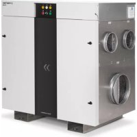
TTR 2800 - Humidifier TROTEC - Free user manual and instructions
Find the device manual for free TTR 2800 TROTEC in PDF.



| Product type | Adsorption dehumidifier |
| Brand | Trotec |
| Model | TTR 2800 |
| Dehumidification capacity | 15.7 kg/h (at 20 °C / 60 % RH) |
| Max. dry air flow rate | 3,150 m³/h |
| Nominal dry air flow rate | 2,800 m³/h |
| Nominal regeneration air flow rate | 570 m³/h |
| Power supply | 3 ph/PE 380-480 V, 50-60 Hz |
| Power consumption | 21.5 kW |
| Nominal current | 31.0 A (at 400 V) |
| Weight | 250 kg |
| Operating temperature range | -20 °C to +40 °C |
| Electrical protection (IP rating) | IP 53 (electrical enclosure) |
| Drying wheel type | Honeycomb silica gel |
| Heat exchanger | Electric, with thermostatic control |
| Air filters | Coarse or fine filters on each air inlet |
| Maintenance | Periodic filter replacement, visual inspection of seals and wheel |
| Safety | STB temperature limiters, differential pressure switch, emergency stop |
| Main functions | Adsorption dehumidification, local/remote mode, time delay |
| Available options | Flowmatic S, electric heater, weather protection |
Frequently Asked Questions - TTR 2800 TROTEC
User questions about TTR 2800 TROTEC
0 question about this device. Answer the ones you know or ask your own.
Ask a new question about this device
Download the instructions for your Humidifier in PDF format for free! Find your manual TTR 2800 - TROTEC and take your electronic device back in hand. On this page are published all the documents necessary for the use of your device. TTR 2800 by TROTEC.
USER MANUAL TTR 2800 TROTEC
Inhaltsverzeichnis
https://hub.trotec.com/?id=42356
TTR 2800

https://hub.trotec.com/?id=42357
TTR 3700

https://hub.trotec.com/?id=42358
Sicherheit
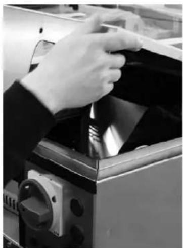
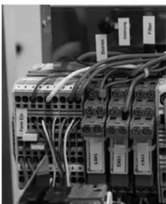
Inbetriebnahme
Voraussetzungen
Bedienung
ACT.Moist Ist-Wert Feuchte in [°Cdp]
Table of contents
Notes regarding the instructions .... 1
Safety 2
Information about the device.... 4
Transport and installation....9
Assembly and installation.... 10
Start-up.... 13
Operation 14
Errors and faults.... 15
Maintenance 18
Harmful influences on rotors 21
Disposal 22
Options.... 23
Technical annex.... 32
Notes regarding the instructions
Symbols

Warning of electrical voltage
This symbol indicates dangers to the life and health of persons due to electrical voltage.

Warning
This signal word indicates a hazard with an average risk level which, if not avoided, can result in serious injury or death.

Caution
This signal word indicates a hazard with a low risk level which, if not avoided, can result in minor or moderate injury.
Note
This signal word indicates important information (e.g. material damage), but does not indicate hazards.

Info
Information marked with this symbol helps you to carry out your tasks quickly and safely.

Follow the manual
Information marked with this symbol indicates that the instructions must be observed.

Wear hearing protection
Information marked with this symbol indicates that you should wear hearing protection.

Wear protective gloves
Information marked with this symbol indicates that you should wear protective gloves.

Wear foot protection
Information marked with this symbol indicates that you should wear safety boots.
You can download the current version of the instructions and the EU declaration of conformity via the following link:
TTR 2000

https://hub.trotec.com/?id=42356
TTR 2800

https://hub.trotec.com/?id=42357
TTR 3700

https://hub.trotec.com/?id=42358
Safety
Read this manual carefully before starting or using the device. Always store the manual in the immediate vicinity of the device or its site of use!

Warning
Read all safety warnings and all instructions.
Failure to follow the warnings and instructions may result in electric shock, fire and / or serious injury.
Save all warnings and instructions for future reference.
- Do not use the device in potentially explosive rooms.
- Do not use the device in aggressive atmosphere.
- Set the device up in an upright and stable position.
- Let the device dry out after a wet clean. Do not operate it when wet.
- Do not use the device with wet or damp hands.
- Do not expose the device to directly squirting water.
- Ensure sufficient lighting at the device.
- Never insert any objects or limbs into the running device.
- Do not cover or transport the device during operation.
- Do not sit on the device.
- Check accessories and connection parts for possible damage prior to every use of the device. Do not use any defective devices or device parts.
- Ensure that all electric cables outside of the device are protected from damage (e.g. caused by animals). Never use the device if electric cables or the power connection are damaged!
- The electrical connection must correspond to the specifications on the nameplate. Additionally, information regarding the electrical connection is provided in the technical annex.
- Insert the mains plug (if any) into a properly secured mains power socket.
- Observe the device's power input, cable length and intended use when selecting extensions to the power cable. Completely unroll extension cables. Avoid electrical overload.
- Before maintenance, care or repair work disconnect the device from the mains and secure it against unauthorized restart.
-
Before carrying out maintenance, care or repair work on the device, remove the mains plug from the mains socket. Hold onto the mains plug while doing so.
-
Do not under any circumstances use the device if you detect damages on the mains plug or power cable. If the supply cord is damaged, it must be replaced by the manufacturer, its service agent or similarly qualified persons in order to avoid a hazard. Defective power cables pose a serious health risk!
- When positioning the device, observe the minimum distances from walls and other objects as well as the storage and operating conditions specified in the technical annex.
- Make sure that the air inlet and outlet are not obstructed.
- Make sure that the suction side is kept free of dirt and loose objects.
- Do not remove any safety signs, stickers or labels from the device. Keep all safety signs, stickers and labels in legible condition.
- Before starting any internal work on the device, discharge the EMC filters, e.g. using load resistors.
- Only transport the device in an upright position.
Intended use
The desiccant dehumidifiers of the TTR series are only to be used for dehumidifying atmospheric air. Any other use possibly exceeding the intended purpose is considered to be improper use.
Intended use comprises:
- observing all the information in the instructions
• compliance with the inspection and maintenance tasks - observing the permissible operating and surrounding conditions according to the technical data (see Technical annex)
The following minimum requirements must be met:
• permissible ambient temperature: -20 °C to +40 °C
• relative humidity: max. 95 % RH non-condensing
After consultation with Trotec other operating conditions are possible with respectively modified versions.
Improper use
- Dehumidifiers are not suited for the installation on or the intake of fluids, e.g. from filled tanks or tubs, flooded installation areas or the like.
- If supplying the system with contaminated air, the "harmful influences on rotors" must be observed!
- Do not expose the device to the weather without suitable protection.
- Any unauthorised modifications, alterations or structural changes to the device are forbidden.
- Any operation other than as described in this manual is prohibited. Non-observance renders all claims for liability and guarantee null and void.
Personnel qualifications
People who use this device must:
- be aware of the dangers that occur when working with electric devices in damp areas.
- have read and understood the instructions, especially the Safety chapter.
The following applies to the staff categories stated below:
Electrically skilled person
Electrically skilled personnel must be able to read and understand electric circuit diagrams, to put electrical systems into service and to maintain them, to wire control cabinets, to ensure the functionality of electrical components and to identify possible hazards from electrical and electronic systems.
Instructed person
Instructed persons have been informed of the tasks they were entrusted with as well as of potential hazards resulting from inappropriate behaviour. They are allowed to operate and transport the device and perform simple maintenance activities (cleaning the housing, cleaning the fan).
The device is to be maintained and looked after by instructed personnel.
Personnel training
- Only trained and instructed personnel may work at or with the dehumidifier – observe the personnel qualifications.
- The responsibilities of the personnel for the following tasks must be clearly defined:
- set-up and assembly
- installation
- start-up and operation
– maintenance and repair
- The control unit may only be operated by instructed personnel.
Personal protective equipment

Wear hearing protection
Wear hearing protection when standing near the running device.

Wear protective gloves
For start-up, maintenance and troubleshooting always wear suitable protective gloves.

Wear foot protection
For transportation, start-up, maintenance and troubleshooting always wear suitable foot protection.
Residual risks

Warning of electrical voltage
Work on the electrical components must only be carried out by a qualified electrician!

Warning of electrical voltage
Make sure to de-energize the device before starting work on electrical components.
Set the main switch to the 0 position or pull the mains plug (if any) from the mains socket.

Warning
Dangers can occur at the device when it is used by untrained people in an unprofessional or improper way! Observe the personnel qualifications!

Warning
The device is not a toy and does not belong in the hands of children.

Warning
Risk of suffocation!
Do not leave the packaging lying around. Children may use it as a dangerous toy.

Caution
Only use residual current devices sensitive to all types of current (type B or B+). The integrated EMC filters can lead to instantaneously tripped RCDs.
Use residual current devices with a minimum triggering level of >300 mA and delayed tripping (type K).
Note
Do not operate the device without an inserted air filter! Without the air filter, the inside of the device will be heavily contaminated. This could reduce the performance and result in damage to the device.
Note
Dirt accumulating inside the rotor can substantially reduce the dehumidification performance or damage the rotor beyond repair.
Supplying the system with contaminated air might damage the rotor. Observe the information regarding "Harmful influences on rotors".
Note
After a power failure the device will restart automatically provided that it was not switched off in the meantime. This behaviour is desired and necessary to ensure operation with little supervision.
Behaviour in the event of an emergency
- Switch off the device.
- In an emergency, disconnect the device from the mains feed-in: Hold onto the mains plug while pulling the power cable out of the mains socket.
- Do not reconnect a defective device to the mains.
Information about the device
General description
Dehumidifiers operating on the desiccant principle are used to tackle drying tasks in the field of process engineering, air-conditioning, on construction sites and for the dehumidification of production and storage facilities, where a particularly low humidity level is required over a broad temperature range.
The desiccation technique enables the safe and economic operation even at low operating temperatures.
Design
The basic device consists of the following components:
- fans for air transport
• air filters behind every air inlet - separate sectors for process air (to be dehumidified) and regeneration air (humid exhaust air)
• purging sector for heat recovery - rotor desiccant wheel for the dehumidification with silica gel
- drive unit with gear motor, toothed belt pulley and toothed belt
• heater battery for heating regeneration air - Depending on the selected options further components are possible (see Technical annex).
During dehumidification the desiccant wheel turns continuously at a low speed (depending on the configuration 2 to 40 rotations per hour).
Via the sectors the desiccant wheel is simultaneously charged with the process and regeneration air so it can constantly absorb and release moisture.
Process air
The air to be dehumidified is sucked in by means of a fan. The process air (4) flows through the desiccant wheel's dehumidification sector (1).
In doing so, the contained moisture is withdrawn by the sorbent (silica gel) and retained (desiccation). Due to physical processes the temperature of the dry air (6) increases. Later the dried air flows towards the dry air outlet.
Regeneration air
The regeneration air (5) is also sucked in with its own fan and guided through the purging sector (3). During dehumidification the desiccant wheel warms up as a result of the released desiccation heat and the regeneration heat. The purging sector (3) serves the purpose of heat recovery and for cooling the desiccant wheel, leading to a reduced energy input and improvement of the dehumidification performance – especially at lower dew points. Whilst flowing through the heater battery (7) the air is heated to approx. 100 °C to 140 °C (depending on the intake temperature) and at the same time the relative humidity is extremely reduced.
In passing through the regeneration sector (2), the thusly prepared air now again absorbs the moisture retained by the silica gel (desorption). Then the extremely humid regeneration air (8) is discharged to the outside via the humid air outlet.
Schematic diagram
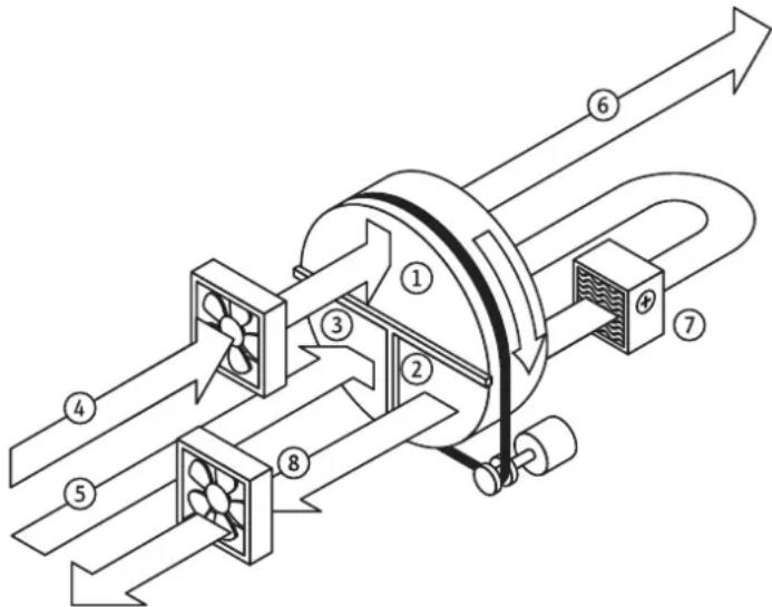
| No. Designation | |
| 1 Dehumidification sector | |
| 2 Regeneration sector | |
| 3 Purging sector | |
| 4 Process air inlet | |
| 5 Regeneration air inlet | |
| 6 Dry air outlet | |
| 7 Heater battery | |
| 8 Humid air outlet (regeneration air) |
Design configuration and components
rotor
The desiccant dehumidifier works with a desiccant wheel (rotor A) which is composed of layers of smooth and corrugated non-woven fabric with chemically bonded silica gel. Thus created is a honeycomb structure with a large number of axial air ducts with a large surface and direct connection to the inner pore structure of the silica gel.
On account of the desiccant wheel's good mechanical and physical properties no silica gel is discharged. It may be supplied with saturated air with a relative humidity of up to 100 % but not with water drops. The rotor is incombustible.
Rotor drive
The rotor is driven by an electric gear motor.
The power is transmitted by means of synchronized pulley and timing belt.
Rotor rotation control
The device is equipped with a rotation control for an early recognition of a possible rotor standstill.
Rotor bearing
The rotor is mounted on a stainless steel axle with maintenance-free plain bearing bushes.
Rotor sealing
An automatically clearance-compensating gasket system seals the rotor and the individual air sectors against one another.
Filter
Air filters are located in each individual air inlet – depending on the field of application designed either as coarse or fine filter for removing the dust in the air currents.
Fans
Used are radial fans or mixed-flow fans with energy-saving EC motors. For an easy adjustment of the volumetric flow rates a potentiometer is located behind the front cover. Therefore, the fan speed for process air and regeneration air can be adjusted according to the specifications. Hence, additional throttle valves in the air lines are rendered redundant.
Regeneration air heater
Heating the regeneration air is effected by means of electric heater batteries consisting of individual resistance heating elements. Depending on the dehumidifier model and size of the heater these can be designed as single- or multi-stage versions. The regeneration temperature is regulated by a thermostatic two-step control.
Safety temperature monitors (STW) measure both the regeneration exhaust air temperature (RAL) and the regeneration air temperature heating (RHZ). Primarily the regulation is geared to a preferably constant RHZ. With a decreasing moisture load however RAL might positively rocket, so that the heating is down-regulated before reaching the RHZ. Achieved in this way is an optimum performance adjustment of the regeneration energy to the operating point.
Safety components
In order to protect the basic device from inadmissible temperatures, it comes equipped with the following safety components:
- a differential pressure switch (ΔP switch) to monitor the air flow direction and the flow rate of the regeneration air
- a safety temperature limiter (STB RHZ) to monitor the max. permissible temperature after heating (thermostat maximum)
- a safety temperature limiter (STB RAL) as rotation control for the rotor; it is situated in the exhaust air flow and tripped by an inadmissible temperature rise resulting from rotor standstill
- Depending on the selected options further components are possible (see Technical annex).
Note
If a safety component is tripped, the device will be switched off (STOP), but the overrun will remain active.
Wait until the entire rundown period has lapsed before accessing internal parts of the device.
Electrical system
The entire switching and control technology is located in the integrated electrical control box on the dryer housing. The electrical control box is designed for a high safety standard with protection type IP53 (see Technical annex).
Depending on the model, the terminals for remote monitoring and control can either be accessed via the front cover or the cover of the control box. This is also the place to access the reset buttons of the safety temperature limiters and the potentiometers for fan regulation. The cable gland for the mains feed-in is located at the side of the device. The power supply is connected directly to the terminals of the emergency stop main switch.
Housing
Depending on the model the housing of the dehumidifier is made of galvanized sheet steel or stainless steel sheet.
Options
There are additional options available for the desiccant dehumidifiers of the "TTR..." series (see also chapter "Options" in these instructions).
Types of application
Key for exemplary types of application:
Circulating air drying for indoor installation
The device is positioned in the room to be dehumidified.
- The device operates in recirculation mode.
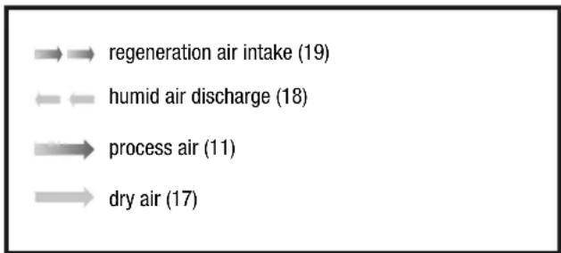
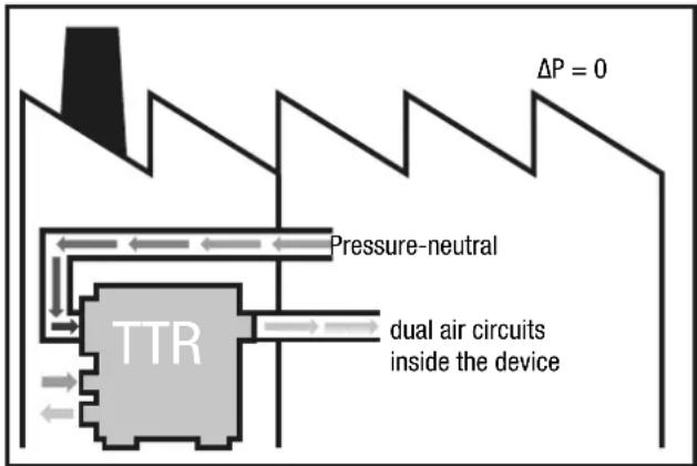
- The air transport line for the regeneration air inlet (19) is to be led outside.
- The air transport line for the humid air outlet (regeneration air (18)) is to be led outside.
Circulating air for drying outdoor installation
- The air transport line for the process air inlet (17) is led into the room to be dried in order to take in the humid air from the room.
- The air transport line for the dry air outlet (11) is led into the room in order to feed dry air into it.
Ventilation mode for outdoor installation
- The air transport line for the dry air outlet (11) is led into the room to be dehumidified in order to feed dry air into it.
Example 1: Circulating air drying for indoor installation
![graph TD A["dual air circuits inside the device"] --> B["Pressure-neutral"] B --> C["TTR"] C --> D["Output"] style A fill:#f9f,stroke:#333 style B fill:#ccf,stroke:#333 style C fill:#cfc,stroke:#333 style D fill:#fcc,stroke:#333](/content/2026/03/541072/images/c74557a029fd60b6214d5f159bc13530d4352561a8bd7787605cea43c66decc0.jpg)
Example 2: Circulating air drying for outdoor installation
Example 3: Ventilation mode for outdoor installation
![graph TD A["TTR"] --> B["excess pressure P+"] B --> C["ΔP"] C --> D["P-"] style A fill:#ccc,stroke:#333 style B fill:#ccc,stroke:#333 style C fill:#ccc,stroke:#333 style D fill:#ccc,stroke:#333](/content/2026/03/541072/images/e33ecdb65918724f3ef4b190bc9f07d401c18021975a4fee605df3900bba2cff.jpg)
Device depiction
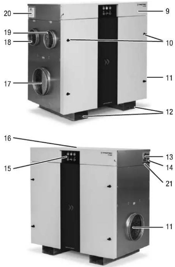
| No. Designation | |
| 9 Front cover (hinged) | |
| 10 Air filter access and maintenance doors | |
| 11 Dry air outlet with connection for an air transport line | |
| 12 Forklift pockets | |
| 13 Main switch with emergency stop function | |
| 14 Cable gland for mains cable (on site) | |
| 15 Control panel | |
| 16 Electrical control box cover | |
| 17 Process air inlet with connection for an air transport line | |
| 18 Humid air outlet (regeneration air) with connection for an air transport line | |
| 19 Regeneration air inlet with connection for an air transport line | |
| 20 Control box ventilation system incl. air filter(s) | |
| 21 Cable inlet for control lines |
Product labelling
For an unmistakable identification, the desiccant dehumidifier is provided with a nameplate.
The nameplate is located inside the control box and in the area of the cable inlet.
The nameplate bears a CE mark.
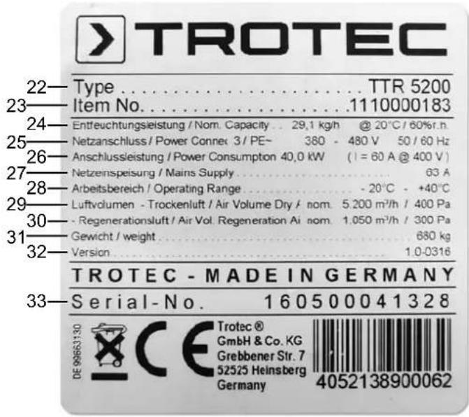
Key
The illustration features the nameplate of a TTR 5200 by way of example. The device-specific information and technical data differ depending on the model and the selected options (see Technical annex).
| No. Designation Unit | ||
| 22 Type or device name | - | |
| 23 Trotec item no. | - | |
| 24 Dehumidification capacity [kg/h] | @ 20 °C / 60 % RH | |
| 25 Power connection | - | |
| 26 Power consumption P = [kW] | I = [A] @ 400 V | |
| 27 Mains supply [A] | ||
| 28 Operating range [°C] | ||
| 29 Dry air volume [m] | 3/h / [Pa] | |
| 30 Regeneration air volume [m] | 3/h / [Pa] | |
| 31 Weight [kg] | ||
| 32 Version | - | |
| 33 Serial number | - | |
Transport and installation

Warning
Risk of severe injuries due to falling device.
The device may only be lifted by use of the forklift pockets or lifting straps. Pipe sockets or other attachment parts must not be used as lifting points! The carrying capacity of the lifting gear must be suitable for the weight of the device (see Technical annex).
Optionally the device is delivered with a transport frame incl. crane lifting lugs with holes for crane eyes or similar (see Technical annex).
The following should be observed before transporting the device using lifting gear:

Warning
Risk of death due to suspended loads.
Make sure that nobody is situated in the immediate proximity.
- Only instructed persons are allowed to perform the transport by use of lifting gear.
- Consider the centre of gravity when transporting the load.
Installing the device
- Position the device on firm, dry and level ground. Depending on the floor load capacity a panel for weight distribution is to be provided. A proper foundation is not necessary.
- Avoid slippery and oscillating ground.
- Position the device allowing a sufficient distance for air inlet and outlet and for connecting the air transport lines.
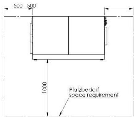
- Make sure there is enough space to operate and maintain the device (see Technical annex).
- Only place the device under a roof. On request devices with a higher type of protection are available for outdoor installation. Make sure that no water can reach the device interior via the air inlet and outlet openings. If required, connect an air transport line to minimize the risk. Optionally the device is delivered with weather protection equipment. Do not expose the device to the weather without this weather protection equipment.
- Ensure a sufficient distance between humid air outlet and air inlet. In case of direct-intake devices the distance between humid air outlet and the suction nozzles should amount to at least 2 m to prevent the humid exhaust air from being sucked right back in.
- The air transport lines must be designed for the available static compression of the fans (see Technical annex).
- The regeneration exhaust air line (C) must be laid with a slight decline (min. 1.5 %) so that possibly accumulating condensate cannot flow back into the device or obstruct the air flow. If an incline cannot be avoided, it is necessary to deliberately create a nadir (lowest point) for draining (e.g. using a syphon).
Inserting the air filter
Note
To avoid damages to the device, do not operate the device without inserted air filters!
Prior to installation and switching the device on, check whether all air filters are inserted.
Information regarding the air filter installation and filter change can be found in the Maintenance chapter.
Schematic diagram
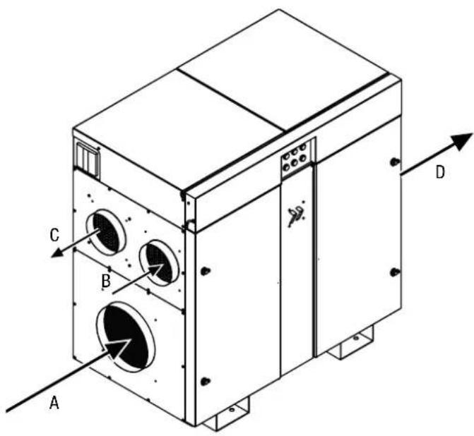
Optionally, a mirror-inverted assembly is also possible.
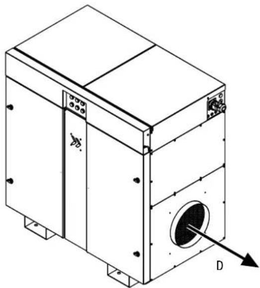
| No. Designation | |
| A Process air inlet | |
| B Regeneration air inlet | |
| C Humid air outlet (regeneration air) | |
| D Dry air outlet |
Assembly and installation
Power connection

Warning of electrical voltage
Work on the electrical components must only be carried out by a qualified electrician!
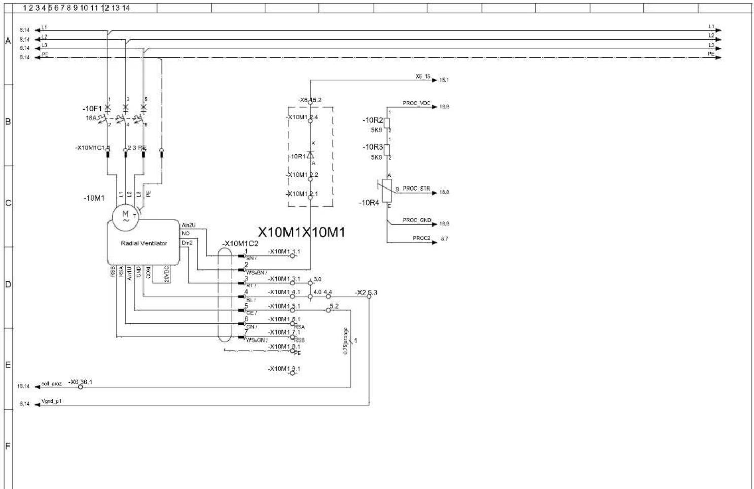
The illustrations below feature the series from the TTR 800 through to the TTR 3700 and can be used exemplarily for all device versions of the TTR series. The mains supply terminals are situated directly at the main switch behind the main switch cover.
- Loosen the two screws (34) of the front cover.
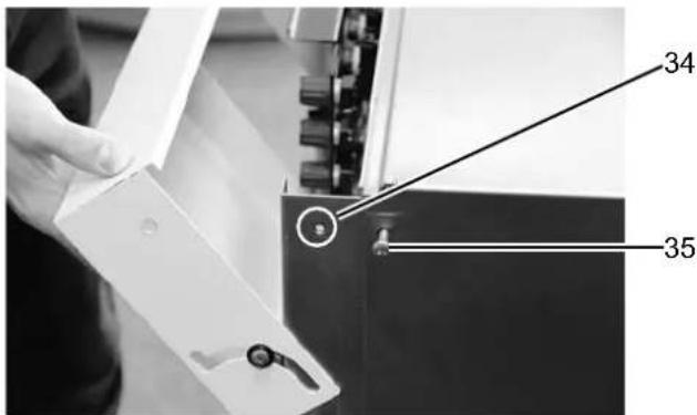
- Slightly lift the front cover and open it.
- Loosen the screws (35) of the electrical control box cover.
- Remove the electrical control box cover either by pulling it forwards or by lifting it.
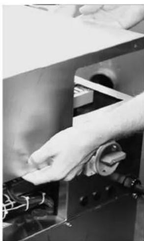
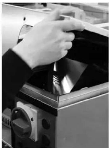
- Guide your mains cable through the cable gland at the device and connect it to the power supply terminals. To connect the device please observe the wiring diagram in the technical annex. The phase sequence can be chosen freely.
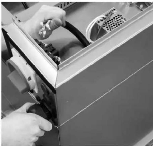
- Fix the cable, screw down the cable gland and observe the strain relief.
In the device version shown below, the mains supply terminals are also situated directly at the main switch behind the main switch cover. The illustrations below feature the series from the TTR 5200 through to the TTR 13500:
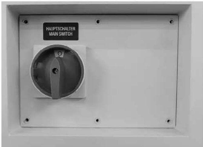
-
Set the main switch to 0.
-
Loosen the screws and open the cover.
⇒ The cover can only be opened if the main switch is set precisely to the 0 position!
- Guide the mains cable through the cable gland at the device and connect it to the power supply terminals. To connect the device please observe the wiring diagram in the technical annex. The phase sequence can be chosen freely.
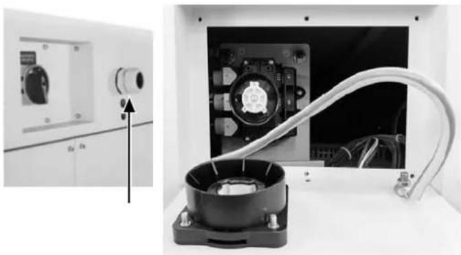
- Fix the cable, screw down the cable gland and observe the strain relief.
Connecting the control lines
Remote ON/OFF
If you want to operate the device optionally via remote mode, e.g. from a remote control centre or factory master control system, connect the external switching contact (N/O contact) to the respective terminals. The control voltage amounts to 24 V DC (for detailed information please refer to the wiring diagrams in the technical annex).
Control via external hygrostat (% RH)
You can control the device via an external hygrostat (option). The control voltage amounts to 24 V DC.
The external hygrostat is to be connected to the terminal strip in accordance with the wiring diagram (see Technical annex).
If the relative humidity level falls below the set target value, the contact closes and terminates the dehumidification process.
The illustrations below show the terminals for remote switch-on and relays with potential-free contacts:
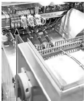
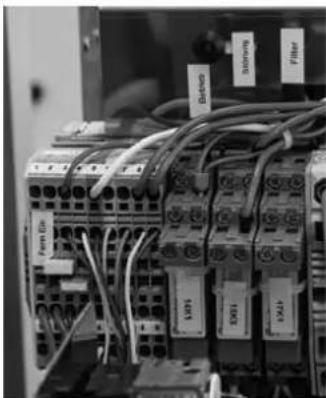
Ventilation mode process air
Select the operating mode Ventilation mode process air if constant air movement is also required at times without the need for drying. If so, reposition the respective jumper (blue) of the corresponding terminals (for detailed information please refer to the wiring diagrams in the technical annex).
The process air fan keeps running even if the hygrostat switches off and the external contact of the hygrostat is opened.
Hygrostat and fan operation are only switches off when switching of the device (STOP), the fan will be switched off at the end of the rundown period.
You can always change back to the normal dehumidification operating mode by replugging the jumper.
Ventilation mode process air can be activated both when in on-site or remote mode.
Remote signalling contacts
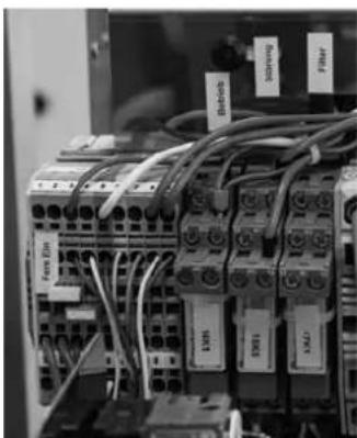
Remote signalling is effected by means of potential-free changeover contacts that can be tapped directly at the corresponding relays.
-
BETRIEB / OPERATION
-
STÖRUNG / FAULT
-
FILTER / WARNING
These remote signalling contacts correlate with the lamps on the control panel (see description in the Operation chapter).
For the correct assignment observe the wiring diagrams in the technical annex.
Inserting the air filter
Check whether all air filters are inserted before switching the device on for the first time. The illustrations below are schematic representations:
- Open the left door of the control cabinet.
- Check whether the correct filters have been inserted in both the process air inlet and the regeneration air inlet (see Technical annex).
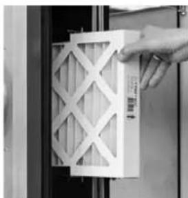
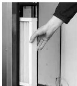
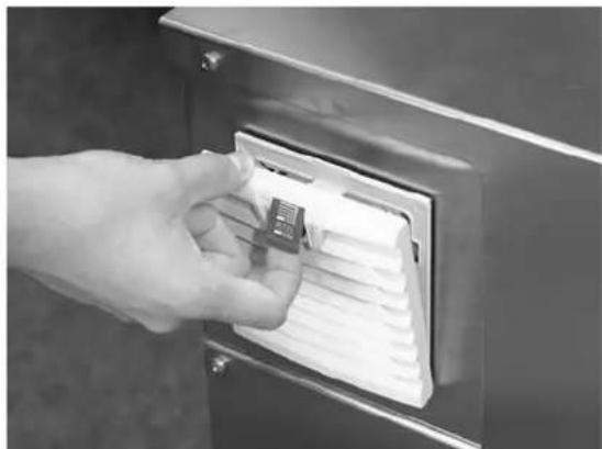
- Check whether the filter for the control box ventilation system has been inserted:
Start-up
Requirements
- Check whether all air filters have been inserted properly.
- Check whether all doors, flaps and covers are closed or screwed in place.
- Check whether all air transport lines have been connected and screwed down properly and whether they are secured by means of tension belts.
- Check whether all air transport routes are clear and free from foreign objects or obstacles.
- Check the permissible operating conditions according to the technical data.
- Make the basic settings while observing the information contained in the Technical annex if applicable.

Warning of electrical voltage
Work on the electrical components must only be carried out by a qualified electrician! Make sure that the electric installation complies with the technical documentation. Ensure the continuity of the protective conductor system.
Initial start-up
If the "Flowmatic S" option is installed, continue with step 4.
For an ideal operation of the device the regeneration air flow must be adjusted according to the technical data.
The potentiometers can be accessed via the front cover:
– target value fan speed process air (Proz.) and
— target value fan speed regeneration air (Reg.) for adjusting the air volume via the fan speed.
For adjustment work, measurements or the like, which have to be carried out during operation, one must on principle switch over to manual operation (ON-SITE)!
- Turn the selection switch to position I.
- Open the front cover (9).
⇒ The two potentiometers are located behind the front cover on the right-hand side:
– target value fan speed process air (Proz.) and
– target value fan speed regeneration air (Reg.) for adjusting the air volume according to the information provided in the technical annex.
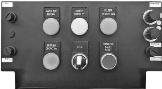
- Adjust the regeneration air volume in ON-SITE mode.
This also allows an adjustment to the on-site air transport lines for optimum operation.
- The proceed as with the normal start-up.
Operation
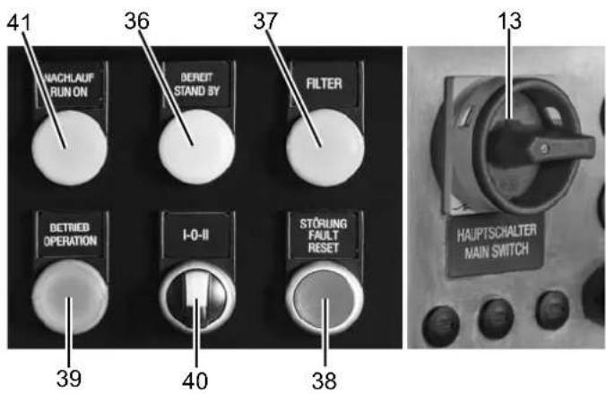
No. Designation
| 13 | Main switch with emergency stop function0: The device is switched off.I: The device is switched on. |
| 36 | BEREIT / STAND BY lampIndicates operational readiness for REMOTE operation:- mains voltage present- selection switch in position II - REMOTE OPERATION- REMOTE-ON not yet activated |
| 37 | FILTER lampIndicates the insufficient air flow rate of one or more air filters. The differential pressure controllers monitor the air flow rate of the filters and so report a dirty filter at an early stage.Replace a dirty filter in due time to prevent an impairment of the device functions. |
| 38 | STÖRUNG / FAULT lamp and RESET buttonCollective fault message with device switch-off (STOP) tripped by- a safety temperature limiter (STB RHZ) to monitor the max. permissible temperature after heating (thermostat maximum)- a safety temperature limiter (STB RAL) as rotation control for the rotor; it is situated in the exhaust air flow and tripped by an inadmissible temperature rise resulting from rotor standstill- a differential pressure switch (ΔP switch) to monitor the air flow direction and the flow rate of the regeneration air- phase error, check the feed-in and fusing- motor fault of the fans regeneration air or process air- possibly collective fault messages of additional options (see Technical annex) |
| No. | Designation |
| 39 | BETRIEB / OPERATION lampIndicates the start-up of the device after switching it on via - selection switch to position Ior - selection switch to position II and remote-ON contact closed |
| 40 | Selection switch ON-SITE/REMOTE OPERATIONI - 0 - II: ON-SITE OPERATIONII: REMOTE OPERATION0: Control OFF (STOP) |
| 41 | NACHLAUF / RUN ON lampIndicates the rundown operation of the device at operating temperature after switching off the control voltage. |
Note:
The main switch serves for switch-on and may only be used as emergency stop switch for disconnection from the mains in case of an emergency.

Warning
In order to prevent a defect of the heater battery due to heat accumulation or an unnecessary tripping of the safety temperature limiter STB when switching off the unit, the regeneration air blower is provided with a temperature-controlled rundown period of approx. 5 minutes.
Wait until the entire rundown period has lapsed before accessing internal parts of the device.
For normal switch-off (STOP) please use the selection switch ON-SITE/REMOTE OPERATION I - 0 - II (40), which initiates the rundown function (NACHLAUF / RUN ON lamp (41) illuminated). Only disconnect the device from the mains for transport or storage via the main switch at the end of the rundown period.
Switching the device on
√ The device is connected to the properly fused feed-in.
-
Turn the main switch (13) to position I.
-
Select the desired operating mode via the selection switch I - 0 - II (40):
A) on-site operation I
Turn the selection switch to position I: the BETRIEB / OPERATION lamp (39) is illuminated – the device starts up.
B) remote operation II
Turn the selection switch to position II: the BEREIT / STAND BY lamp (36) is illuminated until the REMOTE-ON contact is activated – as soon as the REMOTE-ON contact has been activated, the BETRIEB / OPERATION lamp (39) will be illuminated – the device starts up.
Note
In order to attain the full dehumidification performance and to prevent damages due to an insufficient regeneration air flow, the air volumes specified in the technical annex must be observed.
Dirty air filters reduce the volumetric flow rate and must be replaced in due time.
Switching the device off (STOP)
- Turn the selection switch (40) to position 0 or open the REMOTE-ON contact.
→ The BETRIEB / OPERATION lamp (39) goes out.
→ The NACHLAUF / RUN ON lamp (41) is illuminated.
→ The device switches over to rundown operation.
Rundown operation
In order to discharge the trapped heat from the heater, the regeneration air blower will continue to operate for approx. 5 min (temperature-controlled). The control unit remains active. During rundown the device may be restarted at any time.
The fans start up smoothly, delayed by approx. 20 s the device switches into normal operation.
Upon expiry of the rundown period the regeneration air blower stops, the indicator lights go out.
Shutdown
For a complete switch-off, e.g. for transport or maintenance activities, switch the emergency stop main switch (13) to the 0 position at the end of the rundown period.
Storage
- Store the cleaned device in a dry location and protect it against dust.
- Before restarting the device, check the condition of the power cable. If you are doubting its perfect condition, have the cable repaired or call the customer service.
- Have the device checked once a year by an electrically skilled person at any rate.
Errors and faults
The fault recognition switches the device off (STOP), only the rundown operation remains active.
After having eliminated the cause of the fault, the fault message of the STB or rather the STB is to be reset via the corresponding reset button.
- STB RHZ
- STB RAL
-
- possibly reset button for additional options (see Technical annex)
-
Open the front cover and remove the respective cover of the reset buttons.
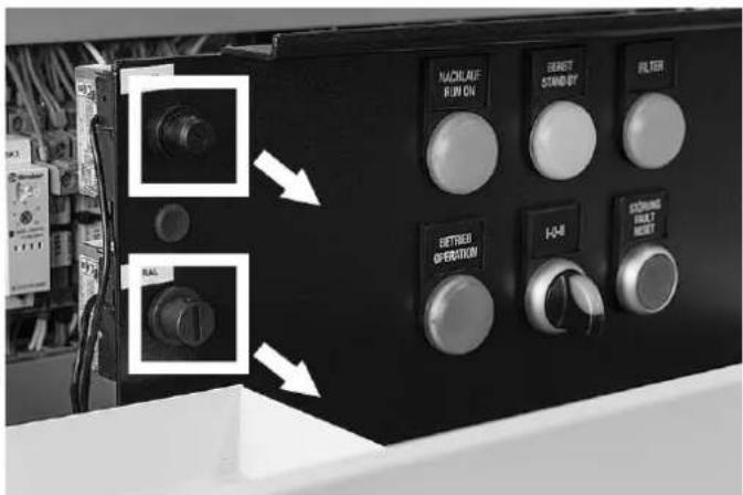
- Press the corresponding reset button and reattach the cover.
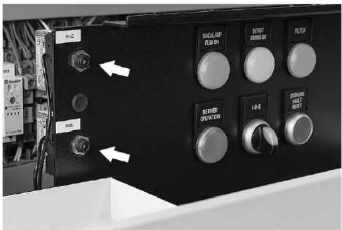
- Then press the STÖRUNG / FAULT – RESET button (38) to acknowledge the STB faults or the ΔP fault message.
Troubleshooting
| Fault Cause of error Measure | ||
| "Fault" indicator light illuminated | rotation control (STB RAL) respondsrotor at a standstillprocess air flow interruptedregeneration air temperature increased inadmissibly | Check thermostat setting.Check rotor drive and toothed belt for proper functioning, repair if necessary.Check process air fan for proper functioning.Check throttle valves, if any.Press reset button. |
| maximum thermostat (STB RHZ) respondsregeneration air flow interruptedregeneration air temperature increased inadmissibly | Check thermostat setting.Check regeneration air fan for proper functioning.Check throttle valves, if any.Check filters.Press reset button. | |
| differential pressure switch for regeneration air does not switch | Check hose connection.Check setting, correct if necessary.Check pressure switch for proper functioning. | |
| fan does not rotate/fans do not rotate See below. | ||
| Insufficient dehumidification performance | air volumes incorrect Calibrate air volumes. | Check filters.Check housing (panels/doors) for air leaks.Check radial and circumferential seal at the rotor.Check throttle valves, if any.Check rotational direction of fans. |
| regeneration heating failed Check heater for proper functioning, measure temperatures, have it replaced if necessary.Check fuses, replace them if necessary.Check relays, contactors, have them replaced if necessary.Check control thermostat setting. | ||
| filter dirty Change filter. | ||
| process air flow interrupted Check process air fan for proper functioning, have it replaced if necessary.Check air passages, flaps. | ||
| rotor is not turning Check belt/chain tension. | Check drive motor for proper functioning, have it replaced if necessary.Check toothed belt pulley for tight fit, fasten it if necessary. | |
| incorrect rotor rotation direction Correct rotational direction. | ||
| Insufficient dehumidification performance | seals are not seated properly or are defective | Correct seal position (particularly radial seals) or replace them. |
| air leaks at nozzles and fansEliminate air leaks. | ||
| regeneration air flow interruptedCheck regeneration air fan for proper functioning.Check air passages, flaps. | ||
| rotor defectiveHave rotor replaced. | ||
| Fans do not rotate electrical supply | interruptedCheck and restore connection. | |
| phase missingCheck phases. | ||
| impeller not fastenedFasten impeller. | ||
| motor defectiveHave motor replaced. | ||
| Metallic sounds, rattling fan impeller | not fastenedCheck process air and regeneration air fan, have them replaced if necessary.Fasten impeller. | |
| toothed belt or chain of rotor drive slipsCheck toothed belt/chain tension.Check toothed washer/pinion and carrier (along rotor circumference) for damage.Check rotor for smooth running, replace bearing if necessary. | ||

Warning
This device can be dangerous if it is repaired by unqualified persons in an improper way. Any faults the elimination of which requires mechanical or electrical intervention may only be carried out by qualified specialists or service staff.
If the fault cannot be rectified despite following the checklist above, please contact one of our subsidiaries or our headquarters.
Maintenance
Activities required before starting maintenance

Warning of electrical voltage
Before starting any internal work on the device, switch the main switch to position 0. For disassembly a cooldown period of at least 30 minutes should be observed. Before starting any internal work, check that all motors and fans are at a standstill and that the device has cooled down.
Activities required before starting maintenance
- For adjustment work, measurements or the like which have to be carried out during operation, always switch over to manual operation (ON-SITE).
- If the dehumidifier was previously operated, one is to wait for the end of the rundown period before switching the device off and for the end of the cool-down period of at least 30 minutes before disassembly.
- Secure all plant sections and operating media (such as vapour) up- and downstream the dehumidifier against inadvertent start-up.
- For all maintenance, inspection and repair work, de-energize the dehumidifier and secure the main switch against inadvertent restart.
- Attach a warning sign and secure the device against restart.
Notes on maintenance and repair activities
- Perform the stipulated adjustment, maintenance and inspection work in due time.
- Inform the operating personnel before starting any maintenance and repair work.
- Upon completion of the maintenance work check all loosened screwed connections for tight fit.
- Upon completion of the maintenance work check all safety devices for proper functioning.
Air filter change
The filter change intervals depend on the degree of air pollution and the filter quality. Dirty filters impair the performance ability of the dehumidifier.
A filter change is required at the latest when the filter change indicator FILTER on the control panel lights up.
Air filters for air inlet, dry air and regeneration air
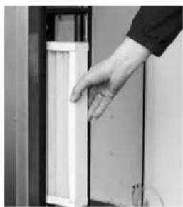
- Open the door for accessing the air filter behind the air inlets. In case of a standard version this means the left door of the cabinet; if mirror-inverted, use the right door.
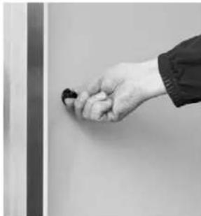
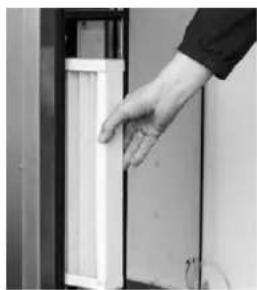
- Pull the filters for the individual air inlet openings out towards the front.
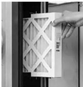
- Change the filters as needed.
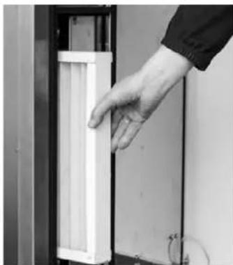
- Then close the cabinet door again.
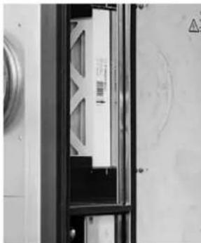
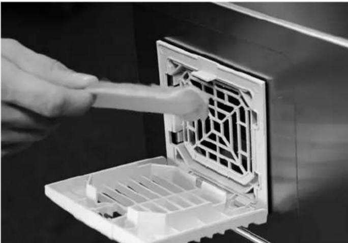
Air filter of the electrical control box
Check the air filter of the electrical control box once a month and replace the filter mat as needed.
- To do so, open the filter flap at the electrical control box.
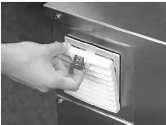
- If it is dirty, replace the filter. Then close the flap again until it snaps into place.
General maintenance
Safe operation of the device requires the components listed below to be checked and cleaned after 12 months at the latest or after every 4000 operating hours as well as all damaged components to be replaced. Furthermore, an electrical safety test must be conducted.
If the device is used in rough surroundings with an increased dust exposure, we recommend performing a visual inspection during every air filter change.
| Component Activity Comments Replacement / | interval | ||
| Differential pressure switch Function test | Switching point As | required if | defective |
| Gear motor Function test 4,000 h | |||
| Solid-state relay SSR Function test Disconnection | As required | ||
| Power relay Function test Disconnection | As required | ||
| Emergency stop main switch Function test | Disconnection of all phases As required | ||
| Regeneration heating Function test Measure currents, clean | surface if necessary As required | ||
| Safety temperature limiter | Function test | Switching point, clean capillary tube | As required |
| Temperature probe | Function test | Check signals, clean probe | As required |
| Temperature monitor | Function test | Switching point, clean capillary tube | As required |
| Thermal switch NO 60 °C | Function test Switching point As required | ||
| Time relay | Function test Time setting | As required | |
| Air filter | Visual inspection | Check condition, replace if necessary | Filter indication |
| Filter fan | Visual inspection | Filter change, clean impeller | As required |
| Radial seals, desiccant wheel | Visual inspection | Check condition, replace if necessary | As required |
| Control cabinet | Visual inspection | Clean, blow out dust if necessary | As required |
| Desiccant wheel | Visual inspection | Obstructions, check surfaces for damage, replace if necessary | As required |
| Door seals | Visual inspection | Check condition, replace if necessary | As required |
| Circumferential seals, desiccant wheel | Visual inspection | Check condition, replace if necessary | As required |
| Regeneration air fan | Visual inspection | Clean impeller, check speed adjustment, measure currents | 4,000 h |
| Dry air fan | Visual inspection | Clean impeller, check speed adjustment, measure currents | 4,000 h |
| Toothed belt | Visual inspection | Check tension and condition, replace if necessary | As required |
| Screw terminal connections | Fit | Retighten if necessary | As required |
| Toothed belt pulley | Fit | Check connection to gear shaft | As required |
Care
Do not use a cleaning agents containing solvents to avoid damage to the surfaces and operating elements of the devices.
Clean the surfaces and operating elements of the devices with a damp cloth and solvent-free cleaning agents only.
Harmful influences on rotors
Some of the substances and compounds listed below are typical examples for substances dissolving the honeycombed silica gel rotors or else negatively affecting the dehumidification performance.
The sorption rotor should not be charged with air which is contaminated with the following or similar substances. Even minor concentrations in the air can have lasting harmful effects on the rotor material and the sorption capacity.
The listed substances remain in the rotor material or the rotor elements and can bring about the following effects:
- Reduced performance owing to the clogging of the silica gel's pores
- Reduced performance owing to the chemical reaction with the silica gel
A) Inorganic substances (examples)
| No. | Substances Chemical formula Effects | ||
| 1 | lithium chloride LiCl reduced productivity of the silica gel | 1 | |
| 2 | sodium hydroxide NaOH destruction of the silica gel structure | ||
| 3 | potassium hydroxide KOH destruction of the silica gel structure | ||
| 4 | sodium chloride NaCl reduced productivity of the silica gel | 1 | |
| 5 | potassium chloride KCl reduced productivity of the silica gel | 1 | |
| 6 | calcium chloride CaCl | 2 | reduced productivity of the silica gel 1 |
| 7 | magnesium chloride MgCl 2 | reduced productivity of the silica gel 1 | |
| 8 | ammonia NH | 3 | destruction of the silica gel structure |
| 9 | hydrofluoric acid | HF | destruction of the mechanical strength of the rotor material |
| 10 | aluminium chloride | AlCl 3 | reduced productivity of the silica gel 1 |
| 11 | sea water | reduced productivity of the silica gel 1 | |
| 12 | steam with a high temperature | destruction of the silica gel structure | |
| 13 | softener | clogs the silica gel pores | |
| 14 | strong acids | pH ≤ 2...3 | destruction of the mechanical strength of the rotor material |
| 15 | bases | pH ≥ 7...8 | destruction of the sorption capacity of the silica gel |
| 16 | amines | R-NH 2 | reduced productivity of the silica gel 1 |
B) Organic substances (examples)
The solvents or volatiles listed below have a high boiling point and a low vapour pressure. Provided these substances are adsorbed by silica gel, they remain in the material on a permanent basis.
| No. | Substances Chemical formula Effects | ||
| 1 oil mist | clogs the silica gel pores | ||
| 2 cyclohexanone | C | 6H10O | reduced productivity of the silica gel 1 |
| 3 isopropyl alcohol | CH | 3H8O | reduced productivity of the silica gel 1 |
| 4 o-xylene | C | 8H10 | reduced productivity of the silica gel 1 |
| 5 m-xylene | C | 8H10 | reduced productivity of the silica gel 1 |
| 6 p-xylene | C | 8H10 | reduced productivity of the silica gel 1 |
| 7 phenol | C | 6H5OH | reduced productivity of the silica gel 1 |
| 8 o-dichlorobenzenes | C | 6H4Cl2 | reduced productivity of the silica gel 1 |
| 9 methyl bromide CH | 3Br | reduced productivity of the silica gel 1 | |
| 10 | glycerin | C3H8O3 | reduced productivity of the silica gel 1 |
1) Reduces the internal pore surface of the silica gel leading to a loss of performance.
Disposal

The icon with the crossed-out waste bin on waste electrical or electronic equipment stipulates that this equipment must not be disposed of with the household waste at the end of its life. You will find collection points for free return of waste electrical and electronic equipment in your vicinity. The addresses can be obtained from your municipality or local administration. For further return options provided by us please refer to our website www.trotec24.com.
The separate collection of waste electrical and electronic equipment aims to enable the re-use, recycling and other forms of recovery of waste equipment as well as to prevent negative effects for the environment and human health caused by the disposal of hazardous substances potentially contained in the equipment.
The information regarding proper disposal of the desiccant dehumidifier is based on the current status of May 2017.
The disposal regulations are likely to have changed by the time of disposal. Therefore you have to inform yourself of the current disposal regulations and take changes into account.
You are responsible for deleting any personal data stored on the waste equipment to be disposed of.

Warning
Potential environmental hazard due to incorrect disposal.
Failure to follow the rules on disposal or an improper disposal of contaminated air filters can lead to environmental hazards.
In order to carry out the disposal professionally, you have to be a qualified specialist.
Recycle empty batteries.
Observe the currently applicable regional and, as the case may be, national disposal regulations.
Supplies
- Shut down the desiccant dehumidifier definitely.
- Disconnect the desiccant dehumidifier definitely from any supplies (current, water etc.).
- Remove any supplies such as air filters, oils, coolant, batteries etc.
- Dispose of these supplies separately according to the applicable regulations.
Components of the desiccant dehumidifier
The desiccant dehumidifier is composed of the following disposable materials:
- Steel, sheet steel, hardened steel, e.g. screws, motor shafts, component parts
- Different types of plastic, e.g. installation material, insulation material, window
• Rubber parts, e.g. seals and feet - Plastic hoses
- Power cables, electric lines, electrical devices such as motors, controls, electronic components, electrical control elements, installation material, sensors
Final disassembly
For disassembly of the desiccant dehumidifier please proceed as follows:
- Carefully disassemble the assemblies and parts that you want to continue to use in order to avoid damage to these parts.
- Take notes so that you can re-assemble the used parts correctly.
- Provide appropriate temporary storage facilities to be able to store the amounts of different materials separately.
- Use the specified fastening elements for disassembly: Remove the specified fastening elements to separate the parts from one another.
- If possible, do not use any angle grinders or welding equipment as this would cause unnecessary additional effort.
- Always work in pairs when disassembling large parts.
- After disassembly has been completed, have the parts collected by a qualified disposal company.
- Store parts to be used again.
Return to manufacturer
The desiccant dehumidifier does not comprise any components that are intended to be returned to the manufacturer.
Notification of authorities and manufacturer
An official deregistration of the desiccant dehumidifier is not required. This could, however, change if the disposal regulations are amended. Make sure to dispose of the desiccant dehumidifier correctly.
Should you be unable to dispose of the device properly, please contact the manufacturer and instruct him to carry out the disposal on your behalf.
Options
Control module Millenium option
With four-line plain text display for status, warning and fault messages.
The device comes equipped with a freely programmable logic module offering the following functions:
Basic functions
• Function monitoring of fans, heating system and rotor drive
- All warnings or faults are displayed in plain text (for full particulars see chapter Errors and faults)
• Information regarding important basic settings and operating conditions (target and actual values) is displayed in plain text
- The energy management is optimized by a constant monitoring and continuous control of the regeneration temperatures RHZ and RAL
Further optional functions (factory configuration required)
- continuous control of the outlet humidity level in partial-load operation (only in combination with a moisture measuring device and humidity control kit)
- continuous control of the outlet temperature of the dry air (only in combination with a temperature probe, temperature control kit, additional electrical heating or air/water heat exchanger with control valve)
- 2-stage air volume switching for reducing the outlet humidity level through a lower volumetric flow (only in combination with Flowmatic S)
• electric reheater for heating the dry air additionally
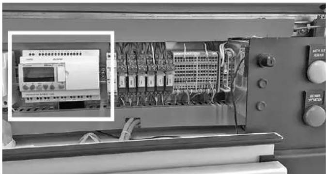
The Millenium control module is located behind the left section of the front cover inside the electrical control box. To be able to read the control module's display, first open the front cover of the device (see instructions):
Operation
The PLC will be activated as soon as the main switch is switched on. The start screen (return) can be opened at any time by pressing the [ESC] button.
Returning to the start screen is also possible via the [B] button:
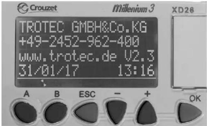
You can browse the screens using the buttons A and B. The following screens will be displayed:
- Welcome and version number.
- Indication of target and actual values for RHZ and RAL temperatures (humid air outlet).
- Indication of target and actual values for differential pressure, humidity level, dew point. The display may vary depending on the option installed.
- Indication of basic settings (distributed over several screen pages).
- Display of basic settings
- Target value inputs for optional additional heating and additional cooling.
- Target value input for optional switch-over to a lower dry air volume.
Operation screens of the control module Millenium
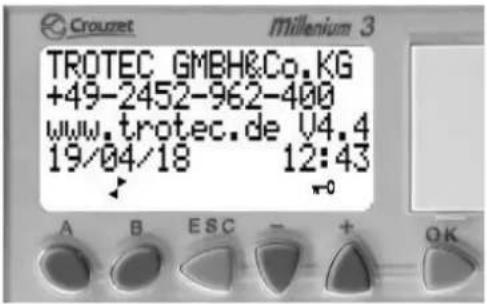
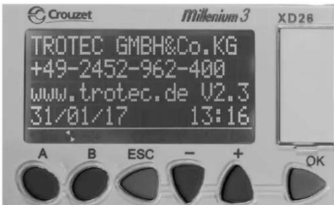
1. Start screen
In addition to the contact data this screen also shows the version number of the installed programme of your Millenium.
Please quote this when contacting.
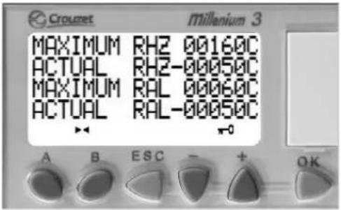
2. Temperature screen
Display of maximum and actual values for the regeneration and exhaust air temperatures
MAXIMUM RHZ Target value regeneration air temperature
ACTUAL RHZ Actual value regeneration air temperature
MAXIMUM RAL Target value regeneration exhaust air temperature
ACTUAL RAL Actual value regeneration exhaust air temperature
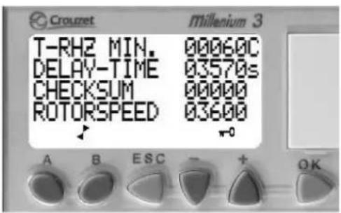
3. Temperature and rotor screen
T-RHZ MIN. Minimum temperature of the regeneration air after completion of waiting period
DELAY-TIME Waiting period in seconds
CHECKSUM Counter for automatic switch-off when hot
ROTORSPEED Current control value of the rotor speed [1/10 h]
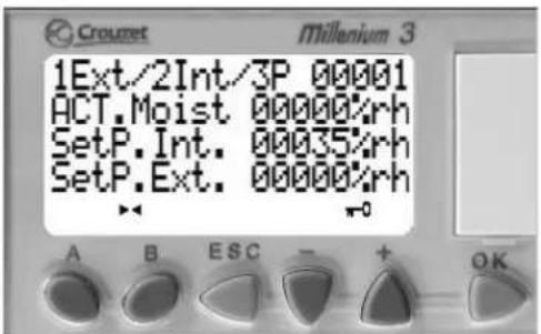
4. Relative humidity screen (optional)
1Ext/2Int/3P Selection target value external = 1, internal = 2, control value external = 3
ACT.Moist Actual value humidity in [% RH]
SetP.Int. Target value humidity in [% RH], can be modified
SetP.Ext. Target value external humidity in [% RH], display only
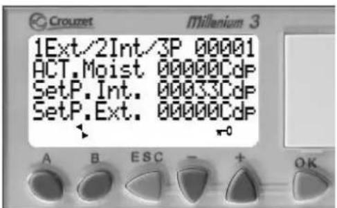
5. Dew point screen (optional)
1Ext/2Int/3P Selection target value external = 1, internal = 2, control value external = 3
ACT.Moist Actual value humidity in [°Cdp]
SetP.Int. Target value humidity in [°Cdp], can be modified
SetP.Ext. Target value external humidity in [°Cdp], display only
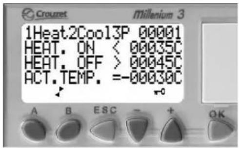
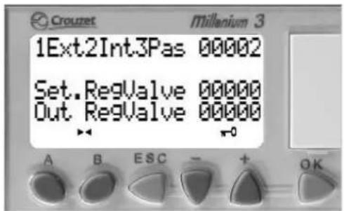
6. Process air regulation – additional heating screen (optional)
1Heat2Cool3P Heating = 1, cooling = 2, transmission external signal = 3
HEAT. ON Switch-on point for additional heating
HEAT. OFF Switch-off point for additional heating
ACT.TEMP. Actual value of the temperature sensor
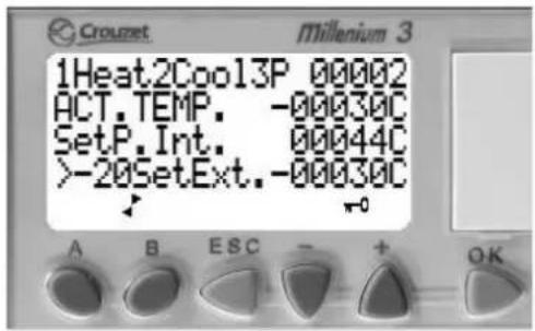
7. Process air regulation screen (optional)
1Heat2Cool3P Heating = 1, cooling = 2, transmission external signal = 3
ACT.TEMP. Actual value of the temperature sensor
SetP.Int. Internal target value
-20SetExt. External target value
Value above -20\ °C = PLC switches over from internal to external target value.
Value below -20 °C = The internal target value applies.
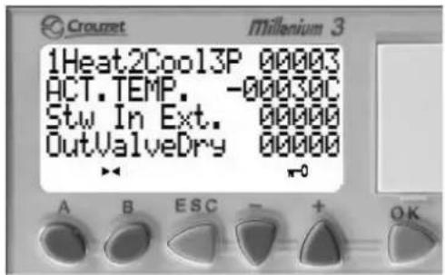
8. Process air regulation screen (optional)
1Heat2Cool3P Heating = 1, cooling = 2, transmission external signal = 3
ACT.TEMP. Actual value of the temperature sensor
Stw In Ext. External control value
OutValveDry Output 06 PWM signal
Control value for control valve
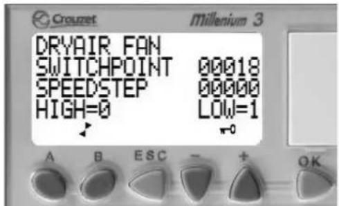
9. Dry air fan screen (optional)
Speed regulation of the process air fan if activated in the service menu
SWITCHPOINT Switching point input
SPEEDSTEP Display of high/low speed level
HIGH=0 / LOW=1 HIGH=0: high speed
LOW=1: low speed
10. Control valve regeneration heating screen (optional)
1Ext2Int3Pas Selection target value external = 1, internal = 2, control value external = 3
Set.RegValve External signal
Out RegValve Output 06 PWM signal
Control value for control valve regeneration heating

Info
All optional displays only appear if the respective function was activated at the factory.
Basic settings
The basic settings are made in the factory. Signal conversions and the corresponding scales must be coordinated with Trotec prior to delivery or can be adjusted (optionally) during start-up by Trotec service personnel.
For applications with moisture control it is recommended to request the Trotec service personnel for possibly required fine adjustments of the control parameters.
Changing values
√ Values that can be modified are highlighted by flashing bars (black bar in the example below).
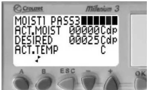
-
Within the screen you can move up and down using the buttons + and -.
-
In order to edit the value, press the OK button. ⇒ The flashing bar disappears and the value is displayed.
-
Press the buttons + or - to increase or reduce the value.
-
Confirm your selection by pressing the OK button. Abort unwanted changes using ESC.
-
Press the buttons + or - to go to the next changeable value.
-
Repeat the steps 2 to 4 until all values are set.
Emergency operation
If the Millenium logic module fails, the following changes have to be made:
- Setting the regeneration air heating to emergency operation

Warning of electrical voltage
Work on the electrical components must only be carried out by a qualified electrician!
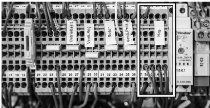
Please proceed as follows to set the regeneration air heating to emergency operation:
-
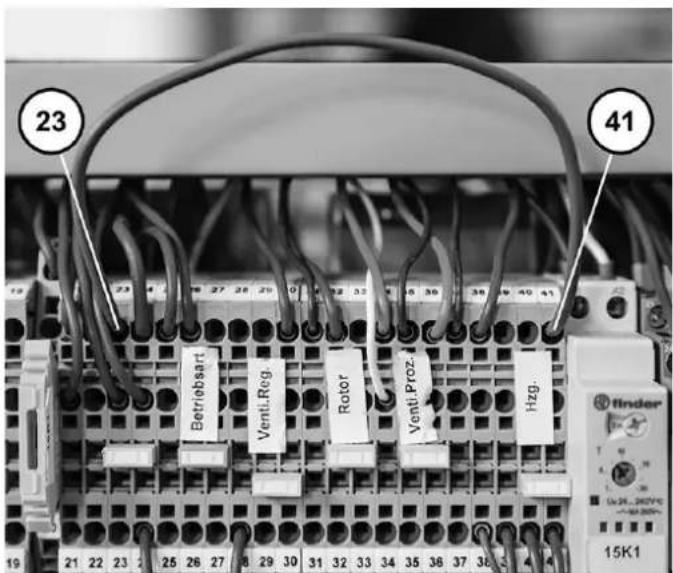
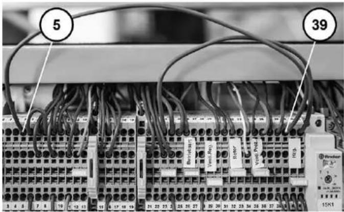
Find the terminals 5, 23 and 39 to 41 on the terminal strip X6.
-
Set the first jumper from X6.23 to X6.41 as shown below.
- Set the second jumper from X6.5 to X6.39 as shown below.
- In the second line from the bottom, disconnect the three wires of the contacts X6.39, X6.40, X6.41 as shown below.
- Isolate each of the three disconnected wires using a luster terminal or similar.
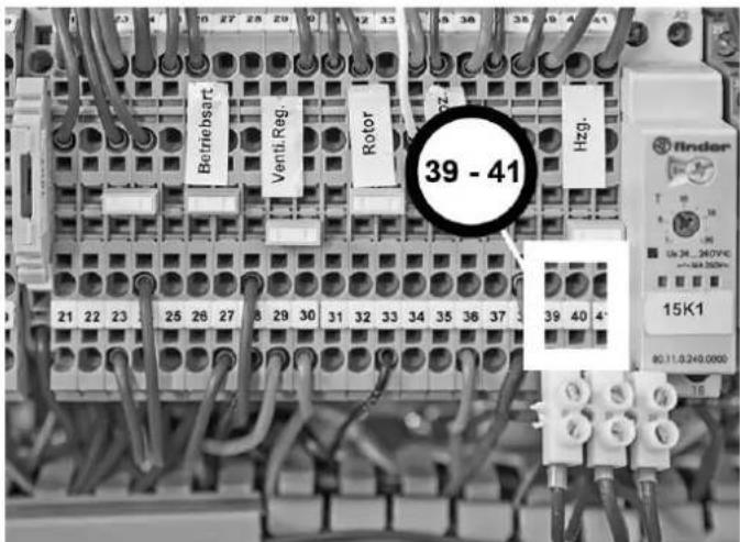
- Set a jumper from X6.40 to X6.41. The modifications are completed.
Warnings and faults
Note
Rectify any faults immediately to ensure economical operation of the device.
- During operation the electrical components relevant for the respective operating mode are monitored for proper functioning.
- In case of failure or malfunctions plain text messages are indicated on the display of the logic module so as to enable quick troubleshooting.
- Depending on the level of impairment of the device's operational safety the messages are divided into warnings and faults.
- A warning does not entail the shutdown of the device and is displayed by periodically recurring plain text messages on the display. The "warning" indicator light lights up.
- In case of faults the device is shut down (STOP) and the indicator light "fault" lights up.
- For reasons of safety the device can only be restarted after the faults have been rectified and the RESET button has been actuated ( => deletes the error memory).
- The source of a fault will be permanently indicated on the display. Until the fault is rectified, it will be displayed again before long whilst the action linked to the fault is triggered.
Error and fault messages can be reset by pressing the reset button.
Warnings
| Plain text message Cause of error Measure | ||
| FILTER WECHSELN (change filter)The differential pressure switches switch via the air filters when the max. permissible pressure drop is exceeded. | ·filter dirty ·Replace all air filters. | |
| HEIZUNG ZU KALT (heating too cold)After 30 min under full load the RHZ temperature must reach a value of at least 60 °C, in controlled operation the value is not prompted. | ·regeneration air not reaching the minimum temperature·regeneration air volume too high·intake temperature too low·control signals interrupted | ·Check heater current, if required, repair heater battery.·Check regeneration air volume.·Check switching devices and contacts. |
| WENIG REGEN.-LUFT (little amount of regeneration air)Differential pressure switch monitors the pressure loss via regeneration heating and regeneration sector at the rotor and releases the heating when a minimum value is reached. | ·regeneration air volume too low·regeneration air filter dirty·pressure loss at piping or on-site components too high·regeneration air fan defective or phases faulty·incorrect flow direction·negative pressure at regeneration air inlet to high | ·Adjust the regeneration air volume.·Replace air filter.·Check piping.·Check rotary field.·Replace fan. |
Faults
| Plain text message Cause of error Measure | ||
| VENTI. PROZ.LUFT (fan process air)Fault message from EC motor | fan reports a faultfan defectivedifferential pressure transmitter defectivephase error/mains supply AC/DC | Check fan, have it replaced if necessary.Check wiring and contacts.Check mains supply.Adjust air volume. |
| VENTI. REGEN.LUFT (fan regeneration air)Fault message from EC motor | fan reports a faultphase error/mains supply AC/DCFan defective | Check fan, have it replaced if necessary.Check wiring and contacts.Check mains supply. |
| ROTOR-ANTRIEB (rotor drive)Rotor rotation control/inductive proximity switch is evaluated | toothed belt slippingtoothed washer loosenedgear motor defectivefuse tripped | Check belt tension and carrier.Tighten toothed washer or have it replaced.Check gear motor, have it replaced if necessary.Check voltage supply and signal line of gear motor. |
| THERMOSTATE (thermostats)Safety temperature limiters (STB) are prompted.If an additional heating is used, the STB is prompted, too. | At least one STB tripped. Check STBs for proper functioning,clean sensors if necessary.Selected max. RHZ is too high.Check setting at STB, adjust.Check regeneration air volume. | |
If the fault cannot be rectified, please contact one of our subsidiaries or our headquarters.
Flowmatic S option
The configuration of Flowmatic S depends on your order.
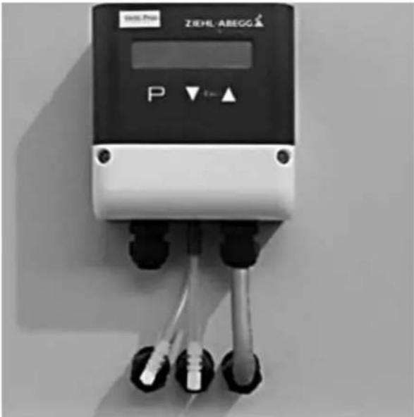
The regeneration air control is configured at the factory and does not require any further adjustment.
Target value control: The process air is set via the "Venti.Proz." potentiometer or an external target value.
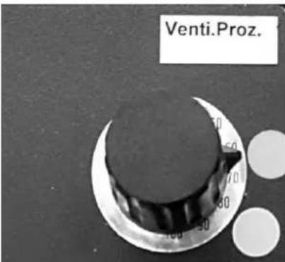
Actual value control: Enter the desired target value at the Flowmatic S (▲ / ▼). For this purpose, keep changing the value until the desired value is shown on the display. The Flowmatic S will now adjust the value until the fan has reached its maximum speed.
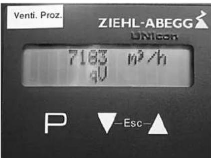
Setting the target value:
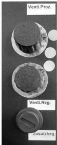
The upper "Venti.Proz." potentiometer serves to define the target value for the process/dry air volume in m3/h . The topmost point roughly marks the regulated nominal air volume and the point in the middle marks the nominal air volume in emergency operation. The points indicate the rough settings for emergency operation (failure of Flowmatic S).
The default values are additionally indicated on a label attached to the Flowmatic S.
The settings for the actual value can be made in the Flowmatic S menu:
![graph TD A["INFO"] --> B["P↓↑ ESC"] B --> C["100 Pa Δp"] C --> D["100 Pa Setpoint 1"] D --> E["▲▼"] F["SETTING"] --> G["P↓↑ ESC"] G --> H["100 Pa Setpoint 1"] H --> I["▲▼"] J["BASE SETUP"] --> K["P↓↑ ESC"] K --> L["4.01 Mode"] L --> M["▲▼"] N["1: 0...200 Pa Measuring Range"] --> O["▲▼"]](/content/2026/03/541072/images/f2bad45eb4d73a8f41ceebb4e476f8d4abcc7bffed4ca83eb546b00e9bf54cd8.jpg)
Note
If "Base Setup" is displayed, you have browsed too far through the menu. Press the "ESC" button in this case.
- Press both buttons ▲ / ▼ simultaneously. The "INFO" menu will be displayed.
- Press the ▼ button until the "SETTING" menu is displayed.
- Press the "P" button.
- Press the ▼ button until the "SETPOINT 1" menu is displayed.
- Press the "P" button. The indication flashes.
- Use the buttons ▲ / ▼ to reduce or increase the set value as desired.
- Finally press the "P" button to save the settings for the new target value.
Electric reheater for dry air option
For additional reheating of the escaping dry air.
The electric reheater is integrated in the "dehumidifier" housing part of the TTR.
The reheating temperature is preset at the factory and generally does not require any modification.
The access for setting the temperature "7B2" of the electric reheater is located in the electrical control box behind the right housing cover.
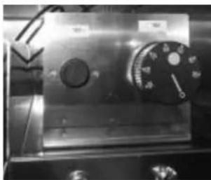
Resetting the safety temperature limiters (STB)
If the temperature limiter has tripped, it must be reset:
-
Open the right control cabinet cover (see Operation chapter in the manual).
-
Unscrew the protective cap of the STB reset device "7B1".
-
The STB can now be reset with a pen or screwdriver.
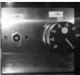
- Afterwards, screw the protective cap back on.
Operation without electric heating

Warning of electrical voltage
Work on the electrical components must only be carried out by a qualified electrician!
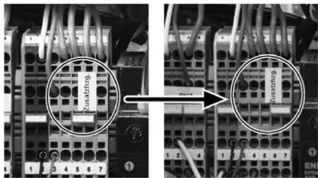
Should it be necessary to operate the desiccant dehumidifier without the electric reheater, simply reposition the jumper.
The jumper for manual changeover is located behind the front cover on the right-hand side.
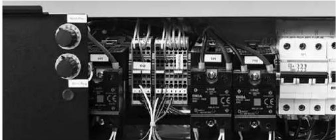
Operation with electric heating Operation without electric heating
Weather protection equipment option
The weather protection equipment prevents the harmful penetration of rain water or similar and comprises:
- weather protection grids at air inlets
• additional seals
• exhaust pipe arc for humid air
• control panel protection
Note
Suitable on-site roofing or similar shall be provided in order to protect the device from a high solar irradiation (overheating) and snow loads (penetration of snowmelt).
Technical annex
Sommaire
Transport et installation....9
https://hub.trotec.com/?id=42356
TTR 2800

https://hub.trotec.com/?id=42357
TTR 3700

https://hub.trotec.com/?id=42358
Normes de sécurité
Transport et installation

Avertissement
Mise en service
Conditions
Utilisation
ID for deviations or additional equipment from the standard device
| SOMOTIME 1:20 | A. P. G. T. H. N. D. DIN ISO 2768-1m | GEMM 34-F | M. O. 2019 | TROTEC Creobener Straße 7, D-32525 Hansborg 32-ONNIGO Maß-Skizze | |||||
| Fis. Nr. | Name: DIN | VW130101 | |||||||
| 3.ATL: | I | CEMC IT | |||||||
| CHENZEN 2012 | Nose | DATUM | |||||||
| DRADE 2012 | YOGAR | 27-02-2015 | |||||||
| DRADE 2012 | |||||||||
| CHENZEN 2012 | |||||||||
| P. M. 11. GEH6520 | IDC INJICMS Z-EA-GEH6520-Komplett-01 | ||||||||
| Tumus | A. K. K. K. K. K. | P. M. | |||||||
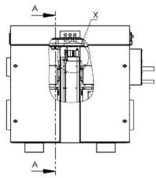
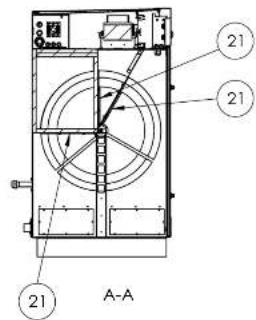
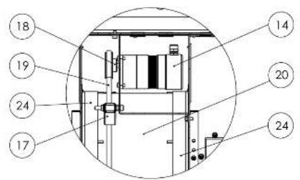
× (1 : 5)
Copying of this Document, and giving it to others and the use of communication of the contents there of, are forbidden without express authority. Offenders are liable to the payment of damages.
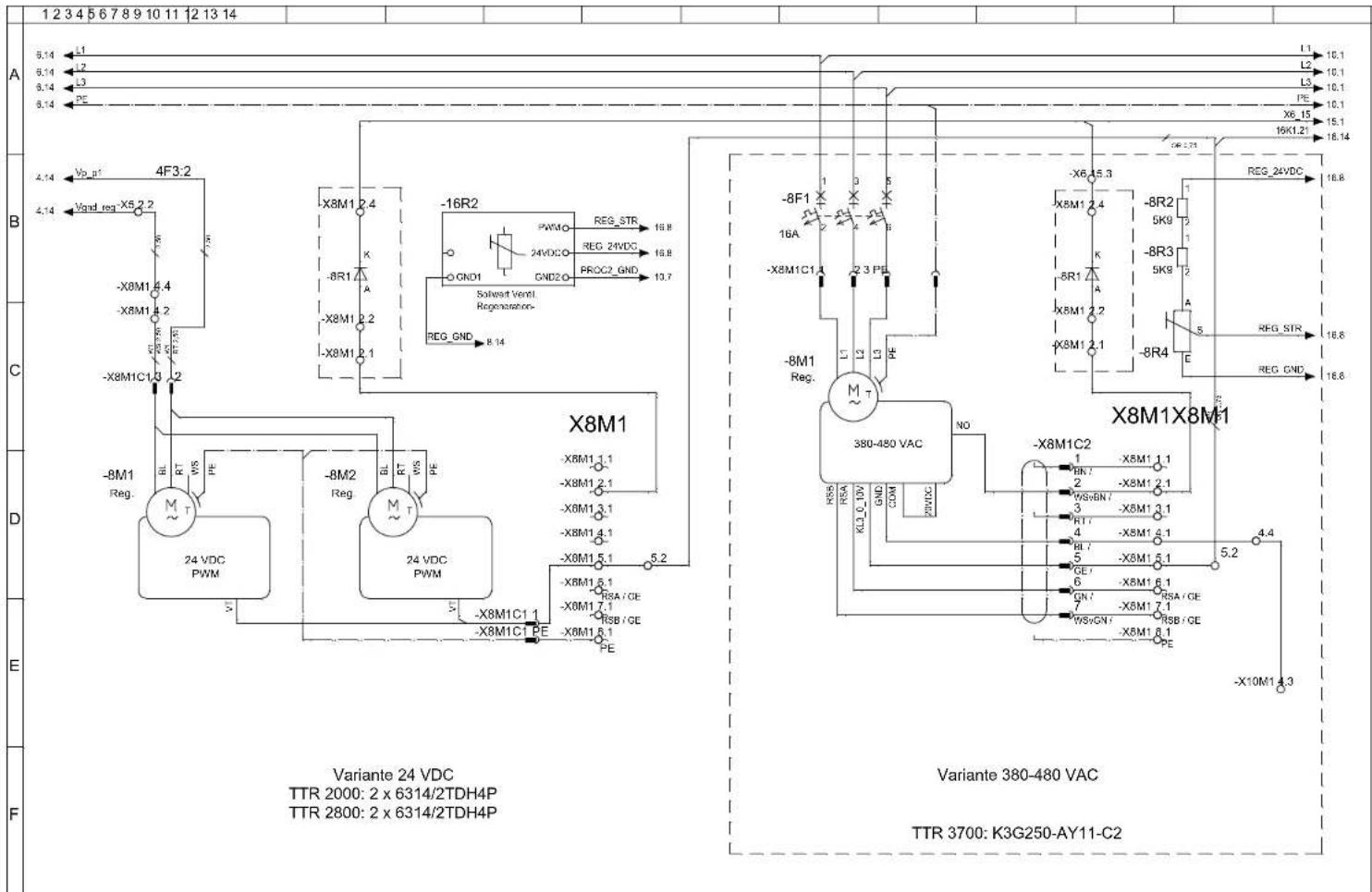
Copying of this Document, and giving it to others and the use of communication of the contents there of, are forbidden without express authority. Offenders are liable to the payment of damages.
In accordance with the EC Machinery Directive 2006/42/EC, Annex II Part 1 Section A
additional directives
2011/65/EU RoHS-Richtlinie/ RoHS Directive/ Directive LdSD
applied harmonized standards
EN ISO 13849-1:2015
applied national standards and technical specifications

- INHALTSVERZEICHNIS
- SICHERHEIT
- INBETRIEBNAHME
- VORAUSSETZUNGEN
- BEDIENUNG
- TABLE OF CONTENTS
- NOTES REGARDING THE INSTRUCTIONS
- SYMBOLS
- WARNING OF ELECTRICAL VOLTAGE
- WARNING
- CAUTION
- NOTE
- INFO
- FOLLOW THE MANUAL
- WEAR HEARING PROTECTION
- WEAR PROTECTIVE GLOVES
- WEAR FOOT PROTECTION
- SAFETY
- INTENDED USE
- IMPROPER USE
- PERSONNEL QUALIFICATIONS
- ELECTRICALLY SKILLED PERSON
- INSTRUCTED PERSON
- PERSONNEL TRAINING
- PERSONAL PROTECTIVE EQUIPMENT
- RESIDUAL RISKS
- BEHAVIOUR IN THE EVENT OF AN EMERGENCY
- INFORMATION ABOUT THE DEVICE
- GENERAL DESCRIPTION
- DESIGN
- PROCESS AIR
- REGENERATION AIR
- DESIGN CONFIGURATION AND COMPONENTS
- ROTOR
- ROTOR DRIVE
- ROTOR ROTATION CONTROL
- ROTOR BEARING
- ROTOR SEALING
- FILTER
- FANS
- REGENERATION AIR HEATER
- SAFETY COMPONENTS
- ELECTRICAL SYSTEM
- HOUSING
- OPTIONS
- TYPES OF APPLICATION
- CIRCULATING AIR DRYING FOR INDOOR INSTALLATION
- CIRCULATING AIR FOR DRYING OUTDOOR INSTALLATION
- VENTILATION MODE FOR OUTDOOR INSTALLATION
- PRODUCT LABELLING
- KEY
- TRANSPORT AND INSTALLATION
- RISK OF SEVERE INJURIES DUE TO FALLING DEVICE
- RISK OF DEATH DUE TO SUSPENDED LOADS
- INSTALLING THE DEVICE
- INSERTING THE AIR FILTER
- ASSEMBLY AND INSTALLATION
- POWER CONNECTION
- CONNECTING THE CONTROL LINES
- REMOTE ON/OFF
- CONTROL VIA EXTERNAL HYGROSTAT (% RH)
- VENTILATION MODE PROCESS AIR
- REMOTE SIGNALLING CONTACTS
- START-UP
- REQUIREMENTS
- INITIAL START-UP
- OPERATION
- SWITCHING THE DEVICE ON
- SWITCHING THE DEVICE OFF (STOP)
- RUNDOWN OPERATION
- SHUTDOWN
- STORAGE
- ERRORS AND FAULTS
- MAINTENANCE
- ACTIVITIES REQUIRED BEFORE STARTING MAINTENANCE
- NOTES ON MAINTENANCE AND REPAIR ACTIVITIES
- AIR FILTER CHANGE
- AIR FILTERS FOR AIR INLET, DRY AIR AND REGENERATION AIR
- AIR FILTER OF THE ELECTRICAL CONTROL BOX
- GENERAL MAINTENANCE
- CARE
- HARMFUL INFLUENCES ON ROTORS
- ORGANIC SUBSTANCES (EXAMPLES)
- DISPOSAL
- POTENTIAL ENVIRONMENTAL HAZARD DUE TO INCORRECT DISPOSAL
- SUPPLIES
- COMPONENTS OF THE DESICCANT DEHUMIDIFIER
- FINAL DISASSEMBLY
- RETURN TO MANUFACTURER
- NOTIFICATION OF AUTHORITIES AND MANUFACTURER
- CONTROL MODULE MILLENIUM OPTION
- BASIC FUNCTIONS
- OPERATION SCREENS OF THE CONTROL MODULE MILLENIUM
- START SCREEN
- TEMPERATURE SCREEN
- TEMPERATURE AND ROTOR SCREEN
- RELATIVE HUMIDITY SCREEN (OPTIONAL)
- DEW POINT SCREEN (OPTIONAL)
- PROCESS AIR REGULATION – ADDITIONAL HEATING SCREEN (OPTIONAL)
- PROCESS AIR REGULATION SCREEN (OPTIONAL)
- DRY AIR FAN SCREEN (OPTIONAL)
- CONTROL VALVE REGENERATION HEATING SCREEN (OPTIONAL)
- BASIC SETTINGS
- CHANGING VALUES
- EMERGENCY OPERATION
- WARNINGS AND FAULTS
- FLOWMATIC S OPTION
- SETTING THE TARGET VALUE
- ELECTRIC REHEATER FOR DRY AIR OPTION
- RESETTING THE SAFETY TEMPERATURE LIMITERS (STB)
- OPERATION WITHOUT ELECTRIC HEATING
- WEATHER PROTECTION EQUIPMENT OPTION
- TECHNICAL ANNEX
- SOMMAIRE
- NORMES DE SÉCURITÉ
- TRANSPORT ET INSTALLATION
- AVERTISSEMENT
- MISE EN SERVICE
- CONDITIONS
- UTILISATION
Brand : TROTEC
Model : TTR 2800
Category : Humidifier