RX6DR light - Remote control toy MULTIPLEX - Free user manual and instructions
Find the device manual for free RX6DR light MULTIPLEX in PDF.

| Brand | MULTIPLEX |
| Model | RX6DR light |
| Category | Receiver for model aircraft |
| Product type | 2.4 GHz M-LINK receiver |
| Number of channels | 6 |
| Reception system | 2.4 GHz FHSS M-LINK (Frequency Hopping Spread Spectrum) |
| Power supply voltage | 3.5 V - 9.0 V |
| Power consumption | Approx. 10 mA (without servos) |
| Dimensions | Approx. 38.0 x 28.0 x 11.5 mm |
| Weight | 10 g |
| Cable length | Power cable: approx. 10 cm (x2); Antenna: approx. 3 cm (x2) |
| Operating temperature | -20°C to +55°C |
| Signal resolution | 12 bit, 3872 steps |
| Pulse duration | Fast response: 14 ms; Standard: 21 ms |
| Diversity function | Dual independent receiver for optimal reception quality |
| Output layout | Inline, suitable for narrow fuselages |
| Safety functions | Programmable HOLD and FAIL-SAFE |
| Indicators | Integrated SET button and LED for synchronization and diagnostics |
| Recommended power supply | 4-6 cell NiCd/NiMH or 2S LiPo/LiIo |
| Compatibility | MULTIPLEX M-LINK transmitters (ROYALpro, COCKPIT SX, etc.) |
| Warranty | According to applicable laws; covers manufacturing defects |
| Recycling | Do not dispose of with household waste; deposit at a collection point |
Frequently Asked Questions - RX6DR light MULTIPLEX
User questions about RX6DR light MULTIPLEX
0 question about this device. Answer the ones you know or ask your own.
Ask a new question about this device
Download the instructions for your Remote control toy in PDF format for free! Find your manual RX6DR light - MULTIPLEX and take your electronic device back in hand. On this page are published all the documents necessary for the use of your device. RX6DR light by MULTIPLEX.
USER MANUAL RX6DR light MULTIPLEX
EN Operating Instructions 7
These operating instructions are an integral part of the product, and contain important information and safety notes. Please store them in a safe place, where you can find them at any time, and pass them on to the new owner if you sell the receiver.
- SPECIFICATION
| RX-6-DR lightM-LINK | RX-7-DR lightM-LINK | |
| Order No. | # 5 5809 # 5 | 5810 |
| Reception system | 2.4 GHz FHSS M-LINKFrequency Hopping Spread Spectrum MULTIPLEX-LINK | |
| Servo channel count | 6 | 7 |
| Servo signal frame rate | Fast response: 14 msStandard: 21 ms | |
| Signal resolution | 12-bit, 3872 steps | |
| Current drain | Approx. 10 mA (excl. servos) | |
| Aerial feed length / aerial length | Feed cable: approx. 10 cm (2 x)Aerial: approx. 3 cm (2 x) | |
| Operating voltage | 3.5 V ... 9.0 V→ 4 - 6 NiCd / NiMH cells (NiXX)→ 2S LiPo / Lilo | |
| Operating temperature range | - 20°C ... + 55°C | |
| Weight | 10 g | |
| Dimensions | Approx. 38.0 x 28.0 x 11.5 mm | |
2. SPECIAL FEATURES
- Small, all-purpose 6-channel / 7-channel receiver exploiting MULTIPLEX 2.4 GHz M-LINK technology, ideal for use in small models.
- Dual receiver: The receiver contains two complete receiving circuits which operate in parallel (receiver diversity). This provides excellent reception quality by minimising directional effects.
- In-line connector arrangement: Ideal for use even in slender fuselages (e.g. F3B, F3J, ...).
• HOLD / FAIL-SAFE function. - Integral SET button and LED: For binding, FAIL-SAFE programming, RESET and operating status information.
3. SAFETY NOTES
⑧ Please read the instructions before using the receiver.
Use the receiver only for the intended applications ( 4.).
⑧ Ensure the power supply is of adequate capacity ( 6.).
⑧ Observe the installation notes ( 9.).
Carry out regular range checks ( 10.).
4. APPLICATION
The RX-6/7-DR light M-LINK is a radio control receiver intended exclusively for use in model sport applications. It is prohibited to use it for other applications, such as man-carrying vehicles or industrial installations.
The RX-6/7-DR light M-LINK was designed with minimum possible size and weight as top priority, and for technical reasons such a unit cannot offer the same reception characteristics as a larger, technically more sophisticated and more expensive receiver. In the interests of safety we recommend that you use a larger receiver wherever space permits. However, under normal conditions it is possible to obtain an excellent reception performance with the RX-6/7-DR light M-LINK provided that all the RC components are arranged carefully, and the two receiver aerials are deployed correctly.
5. COMPATIBILITY
The RX-6/7-DR light M-LINK 2.4 GHz receiver can only be used in conjunction with transmitters which use MULTIPLEX M-LINK transmission technology. As of June 2009 these are:
• ROYALpro 7, 9 and 16 M-LINK.
- ROYALevo or pro 7, 9 and 12 with firmware version V3.xx and the HFM4 M-LINK 2.4 GHz RF module.
• PROFImc 3010, 3030 and 4000 with the HFM3 M-LINK 2.4 GHz RF module.
- COCKPIT SX M-LINK.
- MULTIPLEX transmitters with the HFMx M-LINK 2.4 GHz RF module.
6. POWER SUPPLY
The RX-6/7-DR light M-LINK receiver works with a wide range of voltages from 3.5 V ... 9.0 V, i.e. with receiver batteries consisting of 4 to 6 NiXX cells or 2S LiPo / 2S Lilo batteries.
Note: if you wish to use a five-cell (six-cell) NiXX battery, check that all the servos, gyros and other components to be connected to the system are approved by the manufacturer for use on operating voltages up to 7.5 V (9.0 V). If you wish to use a 2S LiPo (2S Lilo) pack, check that all the servos, gyros and other components to be connected to the system are approved by the manufacturer for use on up to 8.4 V (8.2 V).
⑧ Note: ensure that the power supply is adequate
A power supply system in good condition and of adequate capacity for the specific application plays an indispensable role in the safe operation of any model:
- Use only high-quality receiver batteries of adequate capacity. Balance and maintain them carefully, and charge them fully.
- Ensure that all cables are of adequate conductor cross-section. Keep all wiring as short as possible, and use the absolute minimum of plug / socket connections.
- Use high-quality switch harnesses exclusively.
- Brief collapses in the power supply voltage (lasting a few milli-seconds) have no adverse effect on the receiver. Longer voltage collapses to below 3.5 V may cause a receiver reset, resulting in a brief interruption in reception. This may be due to a receiver battery which is almost flat, too weak or defective, cables of inadequate cross-section, poor-quality connectors or an overloaded or defective BEC system.
7. RECEIVER CONNECTIONS
This receiver employs the UNI connector system, which is compatible with the connector systems used by most radio control manufacturers (e.g. HiTEC, robbe/Futaba, Graupner/JR).
The receiver sockets are marked as follows:
| 1, 2, 3 ... 6(... 7) | Servo sockets, channel 1, 2, 3 ... 6(... 7) |
| B | Receiver battery socket(servo sockets 1 ... 6 (... 7) can also be used).Duplicated on the RX-6-DR light M-LINK |
When connecting the receiver battery, servos, speed controllers ... it is essential to ensure that the connectors are plugged in correctly, and feature compatible pin assignments: ### (see symbol on the receiver)!
8. FIRST USE, FUNCTIONS
8.1 LED codes
| LED code Description | |
| LED Code 0 LED OFF | Battery voltage too low |
| LED Code 1 LED ON | No reception |
| LED Code 2 1,6 sec | Binding process running |
| LED Code 3 1,6 sec | Normal reception in progress |
| LED Code 5 1,6 sec | Confirmation signal |
8.2 Binding
The first time the receiver is used it must be “bound” to the transmitter; this “binding” procedure only has to be carried out once.
⑧ Note:
The signal output to the servo sockets is switched off during the binding procedure. This means that the servos are "soft", and do not move, while the motor connected to a modern electronic speed controller remains OFF due to the lack of a signal. Nevertheless, it is important to secure the model and keep well clear of the power system.
The binding process is necessary in the following cases:
• The first time the receiver is used ( 8.2.1).
• After a receiver RESET ( 8.5).
- If you change the "Fast Response" setting at the transmitter. Please read the appropriate section in the instructions supplied with your transmitter or RF module.
- Changing to operation with limited frequency range due to national regulations in different countries ("France mode"): All M-LINK transmitters can be switched to the so-called France mode, and if you do this the receiver must also be set to France mode by repeating the binding procedure.
- If the receiver is to be operated in conjunction with a different M-LINK transmitter.
8.2.1 Sequence of the binding procedure
- The first step is always to set the transmitter and receiver to Binding mode:
a. Place the transmitter and the receiver aerials close together.
b. Switch the transmitter ON in binding mode.
Note: please read the operating instructions supplied with your M-LINK transmitter or RF module for details.
c. Switch the RX-6/7-DR light M-LINK receiver ON in Binding mode:
- Locate the SET button on the top of the receiver and hold it pressed in.
- Switch the receiver ON, or connect the battery.
- Now release the SET button (not before):
⇒ The binding procedure runs, the LED on the receiver flashes at a high rate (LED code 2 → 8.1).
- Once the transmitter and receiver are bound, both units switch automatically to standard transmit / receive mode:
⇒ The LED on the receiver flashes slowly (LED code 3 → 8.1).
Note: in most cases the binding process only takes a few seconds.
8.2.2 Binding: locating and correcting faults
Fault:
During the binding process the receiver LED continues to flash at a high rate after several seconds.
Cause:
No M-LINK signal of adequate strength detected.
Remedy:
- Reduce the distance between your transmitter and the receiver aerials.
- Ensure that your transmitter is switched ON in binding mode.
- Repeat the binding procedure.
8.3 Switching the receiver ON and OFF in normal mode
8.3.1 Sequence when switching ON and OFF
This is the procedure for switching the RC system ON:
- Switch the transmitter ON.
- Switch the receiver ON.
- The receiver LED flashes slowly and evenly (LED code 3 → 8.1):
⇒ An M-LINK signal is being picked up: the RC system is ready for use.
This is the procedure for switching the RC system OFF:
- Switch the receiver OFF.
- Only now switch the transmitter OFF.
8.3.2 Locating and correcting faults when switching ON:
The receiver LED lights up constantly when switched on (LED code 1 → 8.1), but does not flash.
Cause:
No M-LINK signal detected.
Remedy:
• Is the transmitter switched on?
- Is the transmitter generating an M-LINK signal?
- Are the transmitter and receiver bound to each other?
• Have you carried out a receiver RESET ( 8.5)?
- Have you made changes to the "Fast Response" setting ( 8.2) ?
Fault:
The receiver LED remains off when the unit is switched on (LED Code 0 → 8.1).
Cause:
The operating voltage (battery voltage) is too low.
Remedy:
- Charge the receiver battery or flight battery, or replace it with a charged pack.
8.4 HOLD and FAIL-SAFE
If the receiver detects invalid data (interference), the last valid data is sent to the servos in order to bridge the period of signal loss (HOLD mode).
The effect of the FAIL-SAFE setting is that the servos run to a previously selected setting if interference should occur, once the HOLD period (0.75 seconds) has elapsed.
In its default state and after a RESET the FAIL-SAFE function is switched OFF, and is only activated when you select the FAIL-SAFE settings for the first time. FAIL-SAFE is set using the SET button on the receiver.
Note: if you are using a COCKPIT SX M-LINK or ROYALevo / pro / M-LINK transmitter, you can also set FAIL-SAFE directly from the transmitter.
If you wish to disable FAIL-SAFE again, the receiver must be reset to the default state (RESET 8.5). After a RESET you must repeat the binding procedure ( 8.2.1)!
Note: always activate FAIL-SAFE!
For safety reasons we recommend that you always activate FAIL-SAFE, and ensure that the selected FAIL-SAFE settings will cause the model to take up as safe an attitude as possible (e.g. motor idle / electric motor OFF, control surfaces neutral, landing flaps deployed, tow-release open, ...).
Selecting the FAIL-SAFE settings:
Use your transmitter to move all the servos (and the speed controller) to the desired position. Hold the SET button pressed in briefly (0.5 to 1 second). This stores the servo positions, and the LED flashes to confirm this (LED code 5 → 8.1).
After sixteen seconds in FAIL-SAFE the receiver no longer sends signals to the servos. Analogue servos and some digital servos (see instructions) then become "soft", to avoid them being stalled. Modern speed controllers switch themselves off. However, some digital servos remain "hard" and maintain their last position.
FAIL-SAFE mode is automatically terminated as soon as the receiver picks up valid signals again.
Testing the FAIL-SAFE positions:
Move the sticks to positions other than the FAIL-SAFE settings, and then switch the transmitter OFF: the servos should go into HOLD mode briefly (0.75 seconds), and then move to the FAIL-SAFE positions which you previously selected.
The FAIL-SAFE positions must always be checked and updated when necessary, e.g. when you install the receiver in a new model.
⑧ Checking the FAIL-SAFE function:
Never operate the receiver with the transmitter switched off for longer than it takes to check the FAIL-SAFE function. Caution: the motor could burst into life - injury hazard!
8.5 RESET to default settings
The receiver settings can be reset to the factory default values if you wish. If you do this, please note that all your settings (e.g. bound transmitter, FAIL-SAFE settings) will be lost.
Hold the SET button pressed in for at least ten seconds (as a guide, the LED goes out when you press the button, comes on again after two seconds, then off again after ten seconds).
When the RESET is complete, the receiver LED will flash to confirm the action (LED code 5 → 8.1).
9. INSTALLATION NOTES
- Protect your receiver from vibration, especially in models powered by an internal-combustion engine (e.g. pack it loosely in foam).
- Locate the receiver at least 150 mm away from electric motors, petrol engine ignition systems and any other electronic components such as speed controllers for electric motors and drive batteries. Do not route the aerials close to these components.
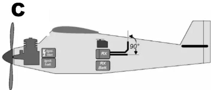
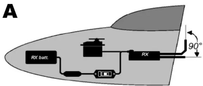
- Install the receiver in the model in such a way that both aerials are as far away as possible from any electrically conductive material, and are arranged at 90° to each other. Position the two aerial tips as far from each other as possible.
- If the model's fuselage contains conductive material (e.g. carbon fibre), the aerials must be installed in such a way that the active part of the aerial (approximately the last 30 mm) is located outside the model.
- Never shorten or extend the aerials or their feed cables!
- Do not deploy the aerials parallel to servo leads, high-current cables or electrically conductive parts (e.g. pushrods).
- Do not deploy the receiver aerials inside or on model components which are laminated or reinforced with electrically conductive materials (metal foil, carbon fibre, metallic paints etc.), as they have a shielding effect.
- Note the recommended installation scheme ( 14., sketches A - C)!
- High-current cables, e.g. those attached to the speed controller, motor and flight battery, should be kept as short as possible.
- If you are using a diode-based battery backer, always install a PeakFilter (# 8 5180).
- Reception quality can be optimised by fitting a special ferrite ring (# 8 5146) or suppressor filter lead (# 8 5057) in the speed controller cable. It is also advisable to fit effective suppressors to conventional (brushed) electric motors (not brushless types) (e.g. use the suppressor set # 8 5020).
10. RANGE CHECKING
Regular range checks are very important - even when using a 2.4 GHz system - in order to ensure reliable operation of the radio control system, and to enable you to detect sources of interference in good time. This applies in particular:
- Before the use of new or changed components, or existing components in a new or modified arrangement.
- Before re-using radio control system components which were previously involved in a crash or a hard landing.
- If you have encountered problems on a previous flight.
Important:
- Always ask a second person to help you with your range check, so that one of you can secure and observe the model.
- If possible, carry out the range check when no other transmitters are operating.
Carrying out the range check:
- Select "Range check" mode on your transmitter (see the operating instructions for the M-LINK transmitter or the
HFM3 M-LINK / HFM4 M-LINK / HFMx M-LINK 2.4 GHz RF module).
- The range of the RX-6/7-DR light M-LINK receiver must be at least fifty metres with the transmitter set to low power. You have reached the range limit when the servos start to move jerkily.
There must be visual contact between the transmitter and receiver aerials (i.e. the model) during the range check.
Keep the transmitter and the model about one metre above ground during the range check.
- If your transmitter features an automatic servo test facility, we recommend that you activate it for one control function (e.g. rudder). This sets up a steady movement of the servo, and enables you to detect the limit of range clearly.
Important:
Carry out the first range check with the motor switched off. Turn the model into all attitudes, and attempt to optimise reception by changing the position of the two aerials.
For the second range check, run the motor at varying speeds and check that the effective range is not significantly reduced. If there is a marked reduction, locate and eliminate the cause of the interference (caused by the motor, the arrangement of the receiving system and power supply, vibration, etc.).
11. CE CONFORMITY DECLARATION
This device has been assessed and approved in accordance with European harmonised directives.

This means that you possess a product whose design and construction fulfil the protective aims of the European Community designed to ensure the safe operation of equipment.
The detailed CE conformity declaration can be downloaded in the form of a PDF file from the Internet under www.multiplex-rc.de. It is located in the DOWNLOADS area under PRODUKT-INFOS.
12. DISPOSAL NOTES
Electrical equipment marked with the cancelled waste bin symbol must not be discarded in the standard household waste; instead it should be taken to a suitable specialist disposal system.
In the countries of the EU (European Union) electrical equipment must not be discarded via the normal domestic refuse system (WEEE - Waste of Electrical and Electronic Equipment, Directive 2002/96/EG). You can take unwanted equipment to your nearest local authority waste collection point or recycling centre. There the equipment will be disposed of correctly and at no cost to you.
By returning your unwanted equipment you can make an important contribution to the protection of the environment!
13. GUARANTEE / LIABILITY EXCLUSION
The company MULTIPLEX Modellsport GmbH & Co.KG accepts no liability of any kind for loss, damage or costs which are due to the incorrect use and operation of this product, or which are connected with such operation in any way. Unless the law expressly states otherwise, the liability on the part of MULTIPLEX Modellsport GmbH & Co.KG to pay damages, regardless of the legal argument employed, is limited to the invoice value of those products supplied by MULTIPLEX Modellsport GmbH & Co.KG which were directly involved in the event in which the damage occurred. This does not apply if liability is incurred according to statutory law on account of intentional or gross negligence.
We guarantee our products in accordance with the currently valid statutory regulations. If you wish to make a claim under guarantee, your initial course of action should always be to contact the dealer from whom you purchased the equipment.
The guarantee does not cover faults and malfunctions which are caused by the following:
- Incorrect or incompetent use
- Maintenance carried out incorrectly, belatedly or not at all, or not carried out by an authorised Service Centre
- Incorrect connections
- The use of accessories other than genuine MULTIPLEX items
- Modifications or repairs which were not carried out by MULTIPLEX or by an authorised MULTIPLEX Service Centre
• Accidental or intentional damage
• Defects due to normal wear and tear - Operation of the unit outside the limits stated in the Specification
- Operation of the unit in conjunction with equipment made by other manufacturers.
14. RECOMMENDED INSTALLATIONS
text_image
A RX batt. 90°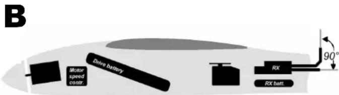
text_image
B Drive battery Motor speed control. RX RX batt. 90°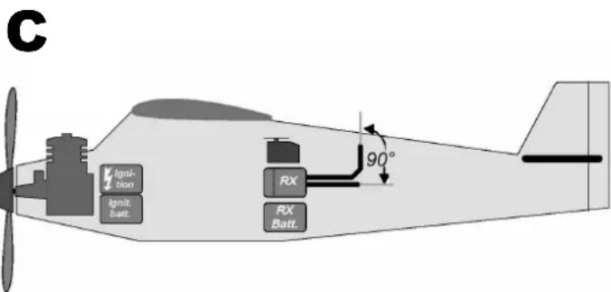
text_image
C Ignition Ignit. Batt. RX RX Batt. 90°Test des positions FAIL-SAFE:
text_image
B Drive battery Motor speed control RX RX belt 90°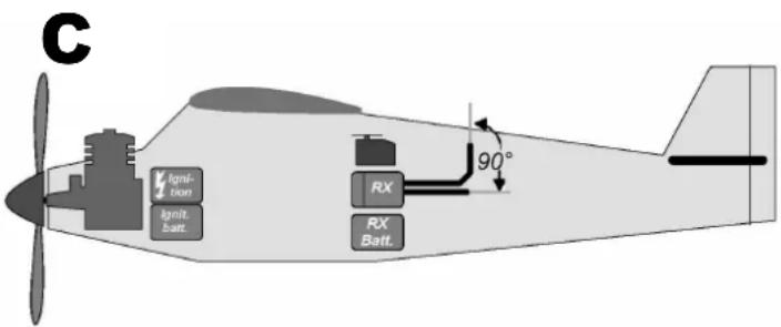
text_image
C Ignition Ignit. Batt. RX RX Batt. 90°8.4 HOLD e FAIL-SAFE
text_image
B Drive battery Motor speed control. RX RX belt. 90°