
RV 3.5 - Rear Camera AEG - Free user manual and instructions
Find the device manual for free RV 3.5 AEG in PDF.
| Product type | Rear view camera |
| Brand | AEG |
| Model | RV 3.5 |
| Screen dimensions | Approx. 100 x 75 x 22 mm (L x W x H) |
| Power supply | 12 V DC (screen, camera and transmitter) |
| Screen diagonal | 3.5 inches (8.9 cm) |
| Screen resolution | 320 x 240 pixels |
| Camera resolution | 640 x 480 pixels |
| Camera viewing angle | 110° |
| Night vision | 7 infrared LEDs |
| Camera protection rating | IP68 (waterproof) |
| Camera tilt angle | Adjustable up to approx. 30° |
| Transmission frequency | 2.4 GHz |
| Transmission range | Max. 10 meters |
| Main functions | Wireless transmission, night vision, distance lines, adjustable menus |
| Maintenance and cleaning | Clean with a dry cloth, do not use liquids |
| Safety | Use only with 12 V DC, do not use at speeds over 3 km/h |
| Spare parts and repairability | Replaceable fuse (1A, type T1AL250V) |
| Operating temperature | -10 °C to +50 °C |
| Maximum reverse speed | 3 km/h |
| Package contents | Screen, suction cup mounting arm, 12 V screen cable, camera, mounting brackets, transmitter, cables, ties, screws, nuts, plastic seal, manual |
Frequently Asked Questions - RV 3.5 AEG
User questions about RV 3.5 AEG
0 question about this device. Answer the ones you know or ask your own.
Ask a new question about this device
Download the instructions for your Rear Camera in PDF format for free! Find your manual RV 3.5 - AEG and take your electronic device back in hand. On this page are published all the documents necessary for the use of your device. RV 3.5 by AEG.
USER MANUAL RV 3.5 AEG
natural_image
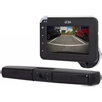
Black-and-white photo of a smart lock device and a digital display screen (no visible text or symbols)INHALTSVERZEICHNIS
1.0 EINLEITUNG
1.1 What are these symbols? 16
1.2 Functionality of the backup camera system 16
1.3 Intended use 16
1.4 Features of the backup camera system 17
2.0 SAFETY INSTRUCTIONS
2.1 General safety instructions 17
2.2 Safety instructions for backup camera installation 18
3.0 PRODUCT DESCRIPTION
3.1 Contents 19
3.2 Product overview 20
4.0 INSTALLATION/OPERATION
4.1 Installing the backup camera system 20
4.2 Installing the monitor 23
4.3 Monitor operation 24
4.4 Monitor menu settings 24
4.5 Testing the backup camera system 24
4.6 Replacing fuses 24
4.7 Troubleshooting 25
5.0 MAINTENANCE AND CARE
5.1 Cleaning, maintenance and storage 26
6.0 TECHNICAL SPECIFICATIONS 26
7.0 DISPOSAL 27
8.0 WARRANTY AND SERVICE 27
1.0 INTRODUCTION
Dear customer,
Congratulations, you have purchased a new „RV 3.5 backup camera system“. Thank you for your trust. To ensure optimal function, performance and safety of your backup camera system please read the instructions for use prior to initial use. This will ensure you will be able to enjoy this equipment for a long time.
1.1 What are these symbols?

Refer to operator's manual

Attention - Danger! Follow safety instructions and warnings!
Warning – dangerous voltage! Risk of fatal injury!

Caution! Risk of electrical voltage around components inside the vehicle!

Dispose of equipment, batteries and packaging in an environmentally friendly manner!

This equipment complies with EU directives

Tested according to ECE 10R-03 0813
Refer to page 26 for additional information about symbols, units and abbreviations.
1.2 Functionality of the backup camera system
The RV 3.5 backup camera system assists with visibility when briefly reversing, e.g. when parking. Pressing the on / off switch will activate the color monitor and, with the car in reverse, the camera picture is wirelessly transmitted from the sender to the monitor. The camera angle of view is 110°. The built-in night vision technology also allows image transmission in the dark. When shifting out of reverse gear, the transmitter will stop transmitting the signal and the monitor image disappears.
1.3 Intended use
The RV 3.5 backup camera system is solely intended to further assist with visibility whilst briefly reversing with a vehicle.
The RV 3.5 backup camera system does not release you of your duty to follow traffic regulations of the Road Traffic Act (RTA) and your due diligence. This backup camera is intended for maximum backup speeds of 3 km/h (kilometers per hour) and a maximum transmission range of 10 m.
The backup camera system is solely intended for private use. The backup camera is solely intended to assist with visibility when reversing with a vehicle. It does not release you of your due diligence to drive carefully and to look around when reversing, especially to pay regard to pedestrians and other traffic!
The backup camera system requires an input voltage of 12 V / DC. Cannot be operated via 24 V / DC!
Attention: risk of property and personal damage!
1.4 Features of the backup camera system
■ Better view behind the vehicle for more safety
- Wireless, encoded 2.4 GHz radio transmission
- Night vision function
- Nice large angle of view (110°)
- Hazard distance guide
- User-friendly menu navigation
- Ideal for car, caravan and trailer
- Easy, low-key installation
- The perfect visual maneuvering and park assistance
- Contents: monitor, monitor bracket, 12 V car adapter, transmitter, camera and mounting materials
2.0 SAFETY INSTRUCTIONS
2.1 General safety instructions

Warning!
Read all instructions! Failure to follow safety instructions may result in property damage, or personal or fatal injuries! Keep these instructions for reference. Keep this operator's manual for future questions and include when passing the equipment on to third parties. Also make the instructions accessible to third parties. The operator's manual is a part of the equipment.

2.1.1 Keep the backup camera system away from children! Children do not understand or recognize the potential risks associated with handling electrical equipment. Keep the backup camera system out of the reach of children and store out of the reach of children. Children could swallow parts and potentially suffocate on them. Children could be injured when using the backup camera system. Also keep packaging materials out of the reach of children.
2.1.2 Keep the instructions for the product's life.
2.1.3 This equipment is not intended to be used by individuals (including children) with limited physical, sensory or cognitive abilities or lacking experience and / or knowledge, unless supervised by an individual responsible for their safety or have been instructed by such on how to use the equipment.
2.1.4 Do not use the backup camera system to power auxiliary automotive equipment or other external devices.
2.1.5 When unsure about installation, operation or the functionality of the backup camera system, contact a trained specialist.
2.1.6 The equipment will heat up during use. Always place the backup camera system in a safe, well ventilated location.
2.1.7 Depending on ambient conditions, the camera and monitor may not always correctly display individuals or objects.
2.1.8 Be sure the equipment is always located in a safe environment. Do not expose the device to mechanical stress, extreme temperatures, moisture or vibrations!
2.1.9 Do not operate the backup camera system if the equipment or cables exhibit damage or malfunctions!
2.1.10 All repairs to the backup camera system must be performed by a qualified electrician / qualified specialist.
2.1.11 The backup camera system may not be modified (altered).
2.1.12 Do not operate the backup camera system after it has been dropped or otherwise damaged. Take to a qualified electrician for inspection or repair!
2.1.13 Do not use other cables or accessories. Do not extend the cables.
2.1.14 Be sure there is ample clearance around the monitor and transmitter to ensure adequate air circulation during use. Do not cover the monitor or transmitter with objects!
2.1.15 Do not use the cable to carry or pull on the camera or transmitter.
2.1.16 Powering the backup camera system requires an input voltage of 12 V / DC. Always disconnect the monitor from the power source by unplugging the 12 V plug when not in use. Never pull on the connector cable to disconnect!
2.1.17 Never allow liquids to enter the monitor! Never immerse the monitor in liquids! Only operate the monitor dry.
2.1.18 The camera is protected against rain but not waterproof! Do not immerse camera in water or other liquids!
2.1.19 Be sure all plugs and power cables are dry. Never power on the equipment with moist or wet hands!
2.1.20 The backup camera system may interfere with other cordless equipment (e.g. mobile phones, Bluetooth equipment) during use or receive interference. Thus, do not use such equipment near the backup camera system or this system near other wireless equipment.
2.1.21 Extreme high or low temperatures or rapid temperature changes may cause the camera to not function properly or cause the monitor to not show objects correctly.
2.1.22 Bright light hitting the camera lens directly may result in objects being overexposed and not being displayed clearly.
2.1.23 After using a car wash, the camera's detection range may change due to mechanical effects. Be sure to check for this and readjust the camera if necessary.
2.2 Safety instructions for backup camera installation

2.2.1 Before installing the backup camera system and before each functionality test of the backup camera system, secure the vehicle to prevent it from rolling away. Attention – risk of injury and property damage! Always engage the hand brake and shift into gear! Automatic transmissions must be put into Park and the hand brake engaged!
2.2.2 Do not run or start the vehicle while installing the backup camera system!
2.2.3 Always follow safety instructions if the vehicle is on jacks or a car lift or the like!

2.2.4 Caution! Risk of electrical voltage near the spark coils, distributor cap, ignition cables, spark plugs and
electrical components inside the vehicle!
2.2.5 Follow the automaker's safety instructions and manual!
2.2.6 Only install the backup camera system in a safe environment! Keep clothing, hair, limbs and the backup camera system away from moving and hot engine- and car parts!
2.2.7 During installation be sure cables are securely and tightly mounted. Do not mount these to conductive materials. If cables are run through walls with sharp edges (metal sheets, etc.) use ductwork or conduit to prevent cable damage. Protect cables from damage, do not bend. Immediately replace damaged cables!
2.2.8 Risk of short circuits! Verify the correct polarity when connecting the camera cable to the vehicle power. Refer to the manual for notices and the automaker's wiring diagram.
2.2.9 When installing the backup camera system always be sure the safety and functionality of other systems and equipment in the vehicle is not impaired! Please follow the instructions of the automaker's manual.
2.2.10 If operation system malfunctions and damage to the backup camera system occurs during operation, immediately disconnect the equipment from the 12 V vehicle power supply!
2.2.11 Be sure the ignition and all vehicle loads are powered off before starting with installation of the backup camera system!
2.2.12 Improper installation of the backup camera system may damage the vehicle's electrical equipment. This could result in an accident or fire.
Caution! Risk of property damage and personal injury!
2.2.13 Even if the fuse inside the 12 V plug is tripped, backup camera system's camera and wireless transmitter will remain ready for use.
2.2.14 If you are unsure how to install the backup camera system consult a qualified specialist or have the system installed by a qualified specialist.
2.2.15 When removing dirt or ice and snow from the camera lens be extremely careful so as not to scratch it.
2.2.16 Do not wear metal body jewelry when installing the backup camera system. Doing so could result in a short circuit and burns!
2.2.17 Run the cables so as not to cause tripping hazards and the cables cannot be damaged by e.g. objects with sharp edges! Do not run cables across hot surfaces!
3.0 PRODUCT DESCRIPTION
3.1 Contents
1 LCD - Monitor 3.5" (8.9 cm)
1 Monitor arm with suction cup base
1 Monitor cable with 12 V plug
1 Camera with connector cable
2 Camera mounting brackets
1 Radio transmitter
1 Connector cable for transmitter
4 Cable ties
2 Clamped cable connections
2 Thread screws
2 Locking nuts
1 Plastic ring
1 Instructions for use
Immediately after unpacking check all parts for damage and verify all parts are present!
Do not use the backup camera system if damaged, incorrect on-screen display or if the instructions for use are missing!
Images and actual product may vary slightly. Subject to change for the purpose of technical advances. Accessories not included.
3.2 Product overview
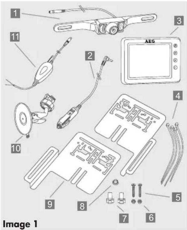
1 Camera with 7 infrared LEDs and connection cable with plug for connecting to the transmitter
2 Monitor cable with 12 V plug for connecting to the cigarette lighter, with 1A (ampere) fuse
3 LCD monitor 3.5" (8.9 cm)
4 Cable ties for securing the transmitting equipment
5 Thread screws for attaching the camera to the mounting bracket
6 Clamping nuts for securing the thread screws
7 Clamped connections for connecting to reversing light wires
8 Plastic ring as edge protector for the cable feed boreholes
9 Brackets for mounting the camera
10 Monitor arm with suction cup base for securing the monitor to the windshield
11 Radio transmitter with connector cable and socket to the camera, including connector cable with a red and black cable for connecting to the reversing light und affixed adhesive strip for attaching the transmitter.
4.1 Installing the backup camera system
Caution! Due to differences in technical and design-related vehicle types, these instructions for use do not apply to all vehicle models.
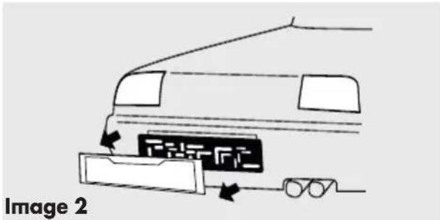
Step 1: Remove license plate
First remove the rear license plate and, if applicable, also the license plate frame (see image 2).
Step 2: Hole for camera cable
Now look for an opening / drill hole near the license plate opening into the interior of the vehicle to feed the connector cable plug of the camera 1 into the interior of the vehicle. For added visibility and easy installation remove the interior trim near the license plate. If the vehicle has no opening, drill a hole using an 11 mm (diameter) drill bit in the area covered by the license plate.

Caution: be sure there are no electrical wires or other automotive parts in the area where you will be drilling
which could be damaged!
To protect the borehole in the metal panel from corrosion the metal edges should be coated with a suitable paint coating (e.g. automaker's touch-up pen) and allow to dry adequately.
Then clip the plastic ring 8 into the borehole from the outside of the vehicle.
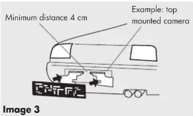
Step 3: Mounting the camera brackets
Mount the two camera brackets 9 and, if applicable, also the number plate frame. Be sure the distance between the two brackets 9 is no less than 4 cm (see image 3). The camera may be mounted above or below the license number. Image 3 shows installation above the license number.
Caution! The location of the camera brackets may not impair the functionality of the license number light! If it impairs the license number light mount the camera on the opposite side.
Step 4: Mounting the camera
Guide the plug for the camera cable 1 through the plastic ring 8 and into the interior of the vehicle or the trunk lid. Mount the camera 1 to the camera brackets 9 evenly spaced from the sides (see image 4). Mount using the two screws 5 and the two clamping nuts 6 (see image 5). Stop turning the clamping nuts when you feel resistance and the camera is securely connected to the bracket. Be sure the cable outlet at the back of the camera always points upward to maintain the maximum swivel range.
The plastic ring 8 may optionally be sealed with conventional sealing compound on both sides to prevent water from entering.
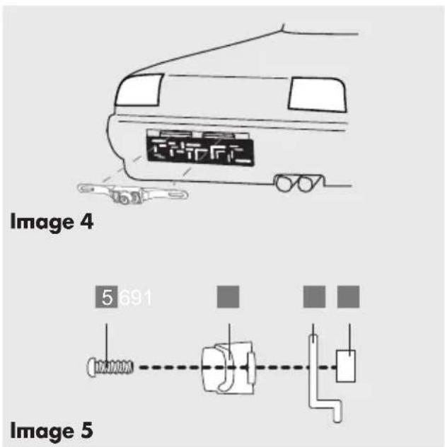
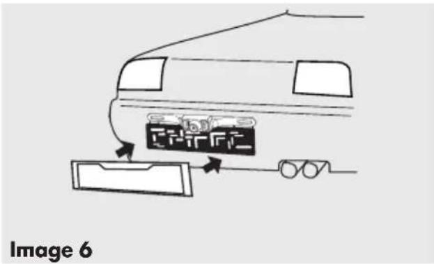
Step 5: Mounting the license number
Now mount the plate (see image 6).
Step 6: Running the camera cable
Now run the camera cable 1 to establish a connection with the cable of the radio transmitter 11 in the vehicle's interior / cavity. Be sure the cables aren't pinched or knotted. Now connect the plug from the camera cable 1 to the socket of the radio transmitter 11.
Step 7: Connecting the transmitter supply cable
Remove the cover of the reversing light. Remove the bulb holder from the reversing light housing. Find the vehicle supply cables to the reversing light. Please refer to the automaker's manual.
Caution! Disconnect the negative cable from the vehicle's battery before working on the vehicle's electric circuit! Stored information, codes and programming may be lost!
Now connect the vehicle's 12 V + (positive) power supply to the reversing light to the red transmitter cable. Then connect the vehicle's 12 V - (negative) earth cable for the reversing light with the black transmitter cable (see image 7).

Using the two cable clamps 7 connect the cables to the reversing light and follow the following steps for connecting the respective cables.
Place the 12 V + (positive) reversing light cable sideways into the clamp connector 7 (see image 8).
Place the red transmitter cable sideways into the clamp connector 7 (see image 9).
Using a pair of pliers (not included) push the protruding metal contact into the cable clamp 7. This will connect the two cables.
Close the cable clamp 7 fuse cover.
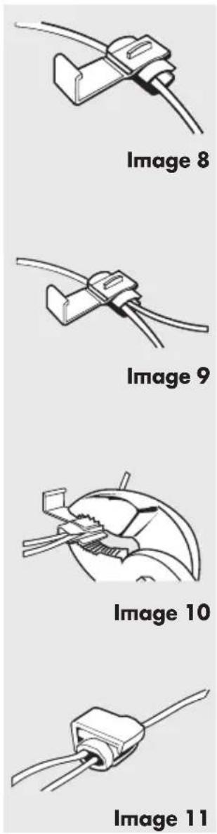
Using the second cable clamp 7 connect the vehicle's 12 V - (negative) reversing light cable with the black transmitter cable as shown in images 8 - 11. Then reconnect the negative cable to the vehicle's battery.

Caution! If you are unfamiliar with the tion and the connections or are unsure with one of these steps, please
consult a specialist regarding the installation! There is a risk of property damage or personal injuries!
Step 8: Installing the transmitter
Remove the protective film from the adhesive strip at the top of the transmitter and affix in a protected location behind the trunk trim. Also secure the transmitter with two cable ties 4. Be sure there are no electrical loads in the direct vicinity of the transmitter to avoid impairing the transmission. Now secure the camera and transmitter cables run in the void of the trunk with cable ties 4. The cables run may not interfere with the vehicle's functionality!
Step 9: Check the transmitter power supply cable
First engage the hand brake and be sure the vehicle is not shifted into gear. Vehicles with automatic transmission must be in "P" for parking lock. Turn the ignition to II but do not start the engine! Push the button 12 (⏻) to power on the monitor. If the transmitter correctly connected, a signal will now be transmitted to the monitor when putting the car into reverse and the monitor displays the camera's viewing range.
If no image is displayed on the monitor you may further check the camera power supply with the hand brake engaged (or vehicle in "P" for parking lock on vehicles with automatic transmission), ignition turned (II) and the vehicle in reverse with a simple test. Do not start the engine! Completely cover the camera with both palms cupped to darken the camera surroundings and activate the night vision sensor. Leave a slight opening between your thumbs and look into your palms. If the camera is active, all 7 LEDs around the camera will light up red. If the LEDs do not light up check the camera's cable and terminal connections. Also see item 4.7 on page 26.
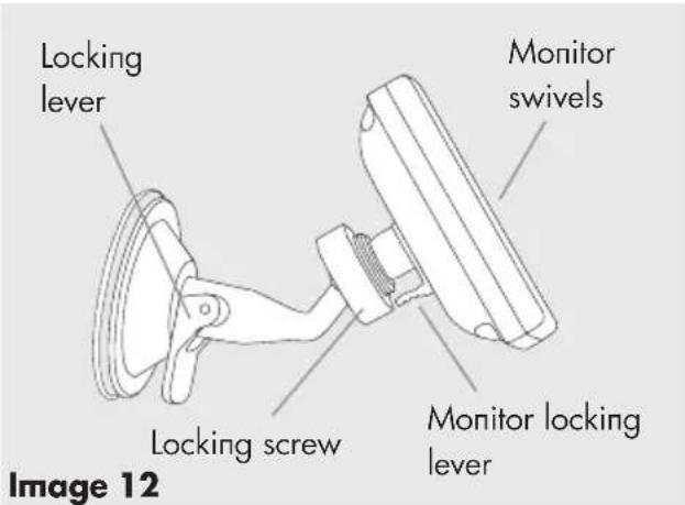
4.2 Installing the monitor
- Insert the square monitor socket on the monitor arm 10 into the designated notch at the back of the monitor. Now slide the monitor bracket upward until it catches (see image 12).
- Open the locknut and adjust the monitor to the desired viewing angle. Now tighten the locknut to secure the monitor.
- Clean the area of the windshield where you would like to attach the suction cup base. Now press the suction cup base onto the windshield and move the locking lever toward the suction cup base.
- Now plug the monitor cable 2 into the vehicle's outlet (12 V). Place the monitor cable so as not to impact or jeopardize the safety of the vehicle and its passengers.

Caution! The location of the monitor may not impair the visibility of the driver! Further, do not impair the functionality and operation of equipment, control units and systems inside the vehicle. Follow applicable laws and safety regulations for vehicles!
4.3 Monitor operation
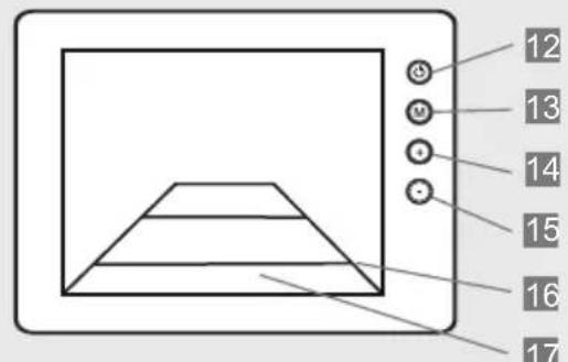
Image 13
12 On / Off button, lights up blue when the monitor is powered on
13 Menu button for selecting the respective adjustment mode
14 Forward / increase button
15 Back / decrease button
16 Guides (distance guides) on the display to assist with reversing
17 Display image
Power on the monitor before using the backup camera and off after use.
4.4 Monitor menu settings
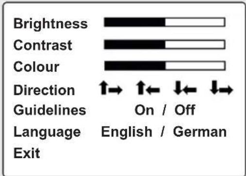
Image 14
- Push the On / Off key 12 so the symbol (_) on the key lights up blue.
- Press the (M) button to access menu mode 13 The display will now show the menu settings for approx. 7 seconds. The respective adjustment mode will be displayed in yellow font.
-
Each time the button (M) is pressed again the menu will advance to the next level of settings.
-
Use the buttons (+) 14 and (-) 15 to increase, decrease or advance the following menu items: Brightness: adjusts the monitor brightness Contrast: adjusts the monitor contrast Color: adjusts the monitor's color intensity Direction: adjusts the monitor display. Adjust image upside down and left / right Guidelines: can be activated or deactivated Language: set language to English / German Exit: leave menu mode
- In "Exit" mode press a (+) 14 or (-) 15 button to leave the menu mode.
4.5 Testing the backup camera system
- First engage the hand brake and be sure the vehicle is not in gear. On vehicles with automatic transmission put the car into "P" for parking lock. Turn the ignition to II, do not start the engine!
- Plug in the monitor 3 by plugging the monitor cable 2 into the 12 V vehicle outlet. Press the button 12 to power on the monitor. The symbol (⏻) on the button must light up blue.
- Now put the vehicle into reverse. The transmitted camera image will now be displayed on the monitor.
4.6 Replacing fuses
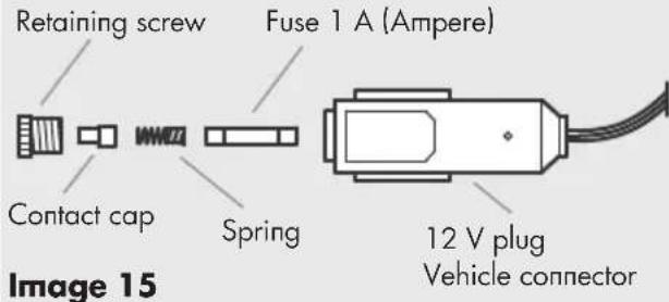
- Unscrew the retaining screw.
- Remove the contact cap, spring and the 1 A (Ampere) fuse.
- Assemble all parts and the new 1 A fuse in the order shown and tighten the retaining screw.
4.7 Troubleshooting
| Solutions, repairPossi | ||
| The vehicle ignition and the monitor are switched on and the car is in reverse but the display remains dark. The blue LED doesn't light up. | The 12 V monitor cable plug is not plugged into the vehicle's cigarette lighter or a 12 V outlet. | Plug the 12 V monitor cable plug into the cigarette lighter or a 12 V vehicle outlet. |
| The fuse inside the 12 V monitor cable plug is burnt out and must be replaced. | Replace the defective fuse inside the 12 V monitor cable plug with a new fuse (see item 4.6). | |
| The fuse for the vehicle's ciga- rette lighter or the 12 V outlet is burnt out and must be replaced. | Replace the defective fuse for the cigarette lighter or the 12 V out- let inside the vehicle's fuse box. | |
| The ignition is switched on, the car in reverse, but the monitor display is blank. | There is no connection between the camera and the monitor. The camera cables may not be correctly connected or have loosened. | Check if the camera connection cable is correctly and securely connected to the reversing light cable. |
| The image on the monitor shows interference. | Other wireless appliances (e.g. mobile phone) are interfering with the signal between monitor and camera. | Switch off all other wireless appliances (e.g. mobile phone). |
| The wireless connection between monitor and camera is too weak, thus interfering with data trans- mission. | Position the transmitter closer to the monitor or adjust the position of the monitor. | |
| The monitor image is not dis- played clearly. | The camera lens may be dirty. | Carefully clean the camera lens. |
| Bright light is hitting the camera lens. | The image quality will improve once you move out of the area of the interfering light. |
5.0 MAINTENANCE AND CARE
5.1 Cleaning, maintenance and storage

5.1.1 Caution! Power off the monitor and unplug the vehicle's 12 V power supply before cleaning the monitor.
5.1.2 Clean the backup camera system with a dry cloth. Do not use liquids or harsh cleaners as these may cause discoloration and damage to the surface of the equipment and the backup camera system may be damaged! Do not allow liquids to enter the equipment! Never immerse the equipment in liquids! Only operate the backup camera system when dry.
5.1.3 Always keep / store the backup camera system in a dry environment! Moisture may damage the electronics of the backup camera system!
5.1.4 Do not store the backup camera system under extreme temperature fluctuations! Condensation generated under these conditions could damage the electronics!
5.1.5 If the camera joint loosens over time you may readjust it. There are 4 screws at the back of the camera inside the camera bracket. Slightly tighten these screws to secure the swiveling camera. This requires the camera to be dismantled.
6.0 TECHNICAL SPECIFICATIONS
Device designation: backup camera system RV 3.5
Item number: 97152
Service and operating -10 ℃ to + 50 ℃
temperature: (Celsius)
Backup speed: max. 3 km/h
(kilometers per hour)
Transmission range: max. 10 m (meters)
Monitor:
Diagonal screen size: 3.5" / 8.9 cm
Resolution: 320 x 240 pixel
Dimensions: approx. 100 x 75 x 22
mm (l x w x h mm)
Technology: LCD color display
Power supply: 12 V (Volt) direct current
Fuse: 1 A (Ampere)
Fuse type: T1AL250V
Camera:
Resolution: 640 x 480 pixel
Night vision: 7 infrared LEDs
View angle: 110°
Color sensor: 1/4 " color CMOS
Exposure automatic
compensation:
White fader: automatic
Camera tilt: variable adjustment angle to approx. 30^
Power supply: 12 V (Volt) direct current
IP Class (protection IP68, waterproof
type):
Transmitter
Transmission: 2.4 GHz (Gigahertz;
cycles per second)
Range: max. 10 m (meter)
Power supply: 12 V (Volt) direct current

This equipment complies with EC directives
■ R&TTE Directive 1999/5/EC
- Electromagnetic Compatibility (EMC) Directive (2004/108/EC)
7.0 DISPOSAL
7.1.1 Any disposal and recycling of the backup camera system must comply with legal provisions. Please contact your municipality or a waste management company for information. Dispose of the backup camera system according to the EC Directive on waste electrical and electronic equipment 2002/96/EC (WEEE).
7.1.2 Follow the applicable waste management laws when disposing of packaging.
8.0 WARRANTY AND SERVICE
Please contact the point of sale or qualified specialists for damage, repairs or other issues with the product.
The general warranty terms apply to defects in production and materials. Please return defective products to the point of sale.
For speedy processing of your warranty claim you will also need:
- Copy of the receipt showing the purchase date.
- Reason for the claim (description of defect).
SOMMAIRE
1.0 INTRODUCTION
Image 14
Immagine 14
Obrázek 14
Obrázok 14
www.aeg-automotive.com
AEG is a registered trademark used under license from AB Electrolux (publ)
- INHALTSVERZEICHNIS
- EINLEITUNG
- SAFETY INSTRUCTIONS
- PRODUCT DESCRIPTION
- INSTALLATION/OPERATION
- MAINTENANCE AND CARE
- INTRODUCTION
- What are these symbols?
- Functionality of the backup camera system
- Intended use
- Features of the backup camera system
- General safety instructions
- Warning!
- Safety instructions for backup camera installation
- Caution! Risk of property damage and personal injury!
- Contents
- Product overview
- Installing the backup camera system
- Step 1: Remove license plate
- Step 2: Hole for camera cable
- Step 3: Mounting the camera brackets
- Step 4: Mounting the camera
- Step 5: Mounting the license number
- Step 6: Running the camera cable
- Step 7: Connecting the transmitter supply cable
- Step 8: Installing the transmitter
- Step 9: Check the transmitter power supply cable
- Installing the monitor
- Monitor operation
- Monitor menu settings
- Testing the backup camera system
- Replacing fuses
- Troubleshooting
- Cleaning, maintenance and storage
- TECHNICAL SPECIFICATIONS
- Monitor:
- Camera:
- Transmitter
- DISPOSAL
- WARRANTY AND SERVICE
- SOMMAIRE
- Immagine 14
- Obrázek 14
Brand : AEG
Model : RV 3.5
Category : Rear Camera