264333 - Remote control toy MULTIPLEX - Free user manual and instructions
Find the device manual for free 264333 MULTIPLEX in PDF.

| Product type | Radio-controlled glider (scale model) - EasyGlider 4 |
| Brand | MULTIPLEX |
| Model | 264333 (EasyGlider 4) |
| Wingspan | 1800 mm |
| Total length | 1100 mm |
| Flying weight | Approx. 1100 g |
| Wing area | Approx. 40 dm² (FAI) |
| Wing loading | Approx. 27 g/dm² |
| RC functions | Elevator, rudder, ailerons, motor (4 channels) |
| Recommended power system | Brushless motor ROXXY C28-34-850kv + ROXXY BL-Control 720 S-BEC speed controller |
| Propulsion battery | LiPo 3S 2200 mAh (ROXXY EVO 3-2200 20C) |
| Material | ELAPOR® foam (use cyanoacrylate or Zacki ELAPOR® glue) |
| Minimum age | 14 years (not a toy for children under 3 years - choking hazard) |
| Center of gravity | 70 mm back from the leading edge (measured at the fuselage) |
| Recommended control throws | Elevator ±10 mm, rudder ±25 mm, ailerons +20/-10 mm |
| Maintenance and cleaning | Clean with a soft, dry cloth. Glue foam parts with cyanoacrylate glue (like Zacki ELAPOR®) or hot glue gun. |
| Safety | Insurance mandatory. Do not use under influence of alcohol/drugs. Danger from rotating propeller. Range test before each flight. |
| Spare parts and repairability | Parts available from dealer or at www.multiplexrc.de. Repair possible with suitable glue. |
| General information | Use exclusively for model aircraft. Follow the instructions in the complete manual. Do not fly over people. |
Frequently Asked Questions - 264333 MULTIPLEX
User questions about 264333 MULTIPLEX
0 question about this device. Answer the ones you know or ask your own.
Ask a new question about this device
Download the instructions for your Remote control toy in PDF format for free! Find your manual 264333 - MULTIPLEX and take your electronic device back in hand. On this page are published all the documents necessary for the use of your device. 264333 by MULTIPLEX.
USER MANUAL 264333 MULTIPLEX
Designed for the MULTIPLEX Brushless Power Set # 33 2672
DE Bauanleitung 2-13
EN Building instructions 14 - 25
FR Notice de construction 26 - 45
IT Instruzioni di montaggio 46-57
ES Instrucciones de montaje 58-69

Abbildungen
Illustrations
Illustrations
Illustrazioni
Ilustraciones
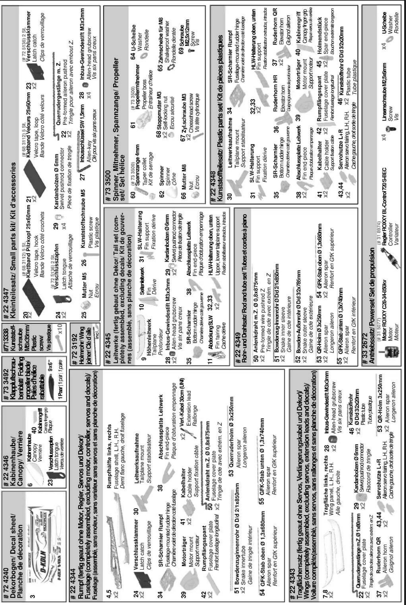
Ersatzteile
Replacement parts
Pièces de rechanges
Part di ricambio
Repuestos
70/7132 - 39
Erhaltliche Varianten / Available versions / Version disponible / Varianti disponibili / Variantes disponibles


214332#264332#214333#13272#13273

This model is NOT A TOY in the usual sense of the term.
By operating the model the owner affirms that he is aware of the content of the operating instructions, especially those sections which concern safety, maintenance, operating restrictions and faults, and is capable of fulfilling these requirements.
This model must not be operated by any child under fourteen years of age. If a person below this age operates the model under the supervision of a competent adult who is acting as the child's guardian within the legal sense of the term, this individual is responsible for the implementation of the information in the OPERATING INSTRUCTIONS.
THE MODEL AND ASSOCIATED ACCESSORIES MUST BE KEPT OUT OF THE REACH OF CHILDREN UNDER THREE YEARS OF AGE! MODELS CONTAIN SMALL DETACHABLE PARTS WHICH MAY BE SWALLOWED BY CHILDREN UNDER THREE YEARS. CHOKING HAZARD!
All the warnings in the OPERATING INSTRUCTIONS must be observed whenever the model is operated. Multiplex Modellsport GmbH & Co. KG accepts no liability for loss or damage or any kind which occurs as a result of incorrect operation or misuse of this product, including the accessories required for its operation. This includes direct, indirect, deliberate and accidental loss and damage, and all forms of consequent damage.
Every safety note in these instructions must always be observed, as all the information contributes to the safe operation of your model. Use your model thoughtfully and cautiously, and it will give you and your spectators many hours of pleasure without constituting a hazard. Failure to operate your model in a responsible manner may result in significant property damage and severe personal injury. You alone bear the responsibility for the implementation of the operating instructions and the safety notes.
Approved usage
The model is approved exclusively for use within the modelling hobby. It is prohibited to use the model for any other purpose than that stated. The operator of the model, and not the manufacturer, is responsible for damage or injury of any kind resulting from non-approved use.
The model may only be operated in conjunction with those accessories which we expressly recommend. The recommended components have undergone thorough testing, are an accurate match to the model, and ensure that it functions safely. If you use other components, or modify the model, you operate it at your own risk, and any claim under guarantee is invalidated.
To minimise the risk when operating the model, please observe the following points:
- The model is guided using a radio control system. No radio control system is immune to radio interference, and such interference may result in loss of control of the model for a period of time. To avoid collisions, you must therefore ensure at all times that there is a wide margin of safety in all directions when operating your model. At the slightest sign of radio interference you must cease operating your model!
- Never operate your model until you have successfully completed a thorough check of the working systems, and carried out a range-check as stipulated in the instructions supplied with your transmitter.
- The model may only be flown in conditions of good visibility. You can avoid being temporarily blinded by not flying towards the sun, or in other difficult light conditions.
- A model must never be operated by a person who is under the influence of alcohol, drugs or medication which have an adverse effect on visual acuity and reaction time.
- Only fly your model in conditions of wind and weather in which you are able to maintain full control of the model. Even when the wind is light, bear in mind that turbulence can form at and around objects which may have an effect on the model.
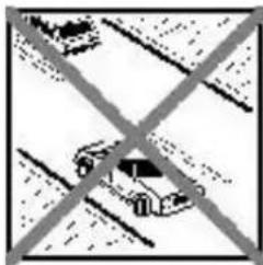
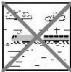
- Never fly in any location where you may endanger yourself of others, e.g. close to residential areas, overhead cables, open roads and railway lines.
- Never fly towards people or animals. You may think that flying low over other people's heads is proof of your piloting skill, but all it does is place others at unnecessary risk. It is in all our interests that you let other pilots know that this is what you think. Always fly in such a way that you do not endanger yourself or others. Bear in mind that even the best RC system in the world is subject to outside interference. No matter how many years of accident-free flying you have under your belt, you have no idea what will happen in the next minute.
Residual risks
Even if the model is operated in the correct manner, and you observe all safety aspects, there is always a certain residual risk.
For this reason it is mandatory to take out third-party liability insurance. If you join a club or flying association, insurance is usually available or included in the annual fee. Make sure that your insurance cover is adequate (i.e. that it covers powered model aircraft). Always keep your models and your radio control equipment in perfect order.
The following hazards may occur owing to the model's construction and type:
- Injury caused by the propeller: you must keep well clear of the area around the propeller from the moment that the battery is connected. Please bear in mind that objects in front of the propeller may be sucked into it, and objects behind the propeller may be blown away by it. The model may start moving when the propeller starts to turn. You must therefore position the model in such a way that it cannot move towards other persons if the motor should unexpectedly start running. When you are carrying out adjustment work involving the running motor, you must ensure that the model is always held securely by an assistant.
- Crash caused by pilot error: this can happen even to the best of pilots, so it is essential to fly exclusively in a safe environment: an approved model flying site and suitable insurance are basic essentials.
- Crash caused by technical failure or unnoticed damage in transit or in the workshop. A thorough check of the model before every flight is essential. However, you should also take into account at all times that material failures can and do occur. Never fly in a location where your model may damage or injure others.
- Keep within the stated operating limits. Excessively violent flying will weaken the airframe, and may result in sudden material failure, or may cause the model to crash during a subsequent flight due to "creeping" consequent damage.
- Fire hazard caused by electronic failure or malfunction. Store batteries safely, and always observe safety notes which apply to the airborne electronic components, the battery and the battery charger. Protect all electronic equipment from damp. Ensure that the speed controller and battery are adequately cooled.
The instructions which accompany our products must not be reproduced and / or published, in full or in part, in print or any electronic medium, without the express written approval of Multiplex Modellsport GmbH & Co. KG.
Examine your kit carefully!
MULTIPLEX model kits are subject to constant quality checks throughout the production process, and we sincerely hope that you are completely satisfied with the contents of your kit. However, we would ask you to check all the parts (referring to the Parts List) before you start construction, as we cannot exchange components which you have already modified. If you find a part is not acceptable for any reason, we will gladly correct the defect or replace the item in question once we have inspected it. Please send the component to our Service Department, with adequate postage pre-paid, being sure to include the completed complaints form. We are constantly working on improvements to our models, and for this reason we must reserve the right to change the kit contents in terms of shape or dimensions of parts, technology, materials and fittings, without prior notification. Please understand that we cannot entertain claims against us if the kit contents do not agree in every respect with the instructions and the illustrations.
Caution!
Radio-controlled models, and especially model aircraft, are by no means playthings in the usual sense of the term. Building and operating them safely requires a certain level of technical competence and manual skill, together with discipline and a responsible attitude at the flying field.
Errors and carelessness in building and flying the model can result in serious personal injury and damage to property. Since we, as manufacturers, have no control over the construction, maintenance and operation of our products, we are obliged to take this opportunity to point out these hazards and to emphasise your personal responsibility.
Warning:
Like every aeroplane, this model has static limits. Steep dives and senseless manoeuvres inappropriate to the type may result in the loss of the aircraft. Please note: we will not replace the model in such cases. It is your responsibility to approach the airframe's limits gradually. It is designed for the power system recommended in these instructions, but is only capable of withstanding the flight loads if built exactly as described and if it is in an undamaged state.
Important note
This model is not made of Styrofoam™, and it is not possible to glue the material using white glue, polyurethane or epoxy; these adhesives only produce superficial joints, and simply break away under stress. Please be sure to use medium-viscosity cyano-acrylate glue exclusively, preferably Zacki ELAPOR® # 59 2727, which is optimised specifically for ELAPOR® particle foam. If you use Zacki ELAPOR® there is usually no need for cyano 'kicker' or activator. However, if you wish to use a different adhesive which requires the use of activator, please note that these materials are injurious to health, and should always be applied in the open air. Take care when handling all cyano-acrylate adhesives, as they harden in seconds, so don't get them on your fingers or other parts of the body. We strongly recommend the use of goggles to protect your eyes. Keep the adhesive out of the reach of children! For certain joints it is also possible to use hot-melt adhesive; the instructions indicate where this is the case.
Working with Zacki ELAPOR®
Zacki ELAPOR® has been developed specifically for glued joints in our models which consist of moulded ELAPOR® foam parts.
Please observe the following points in order to obtain perfect joints:
- Avoid the use of activator. 'Kicker' significantly weakens the joint. We advise leaving joined parts for 24 hours to obtain maximum strength, particularly when the glued area is large.
- Activator should only be used for temporary, small-area joints ('tacking'). Spray a little activator on one surface, and allow it to air-dry for about thirty seconds.
To obtain maximum joint strength you should lightly sand the surface with 320-grit abrasive paper before applying glue.
Bent parts - actually don't exist. If you find that a component has taken up a curve, perhaps after being transported, it is easy to straighten again. In this respect ELAPOR® behaves in a similar way to metal: bend the component back slightly beyond the correct position, and the material will then spring back to its proper shape when released, and maintain it. There are limits, however - don't overdo it!
Specification:
Wingspan 1800 mm
Overall length 1080 mm
Take off mass approx. 1100 g
Wing area approx. 40dm^2 (FAI)
FAI = > wing + tailplane, excl. fuselage)
Wing loading approx. 27g / dm^2
RC functions:
Elevator, rudder, ailerons, motor speed
The Centre of Gravity is located at a point 70mm aft of the wing root leading edge (measured at the fuselage).
BRIEF INSTRUCTIONS
The RTF version of the EasyGlider 4 is factory-assembled, and virtually ready to fly. Numerous procedures which are described in the building instructions are already completed for you, with the result that the model can be ready for the air in very short order.
Tools required
Screwdriver for M5 slot-head screw
It is essential to observe all the safety notes and tips!
Before completing and flying the model please read through the building instructions and the operating instructions for all the components included in the set.
Take particular care over reading the instructions supplied with your SMART SX radio control system!
- Check that the set contents are complete by referring to the Parts List.
- Install the tailplane and fin
See paragraphs 2.12 and 2.13 of the building instructions and Figs. 18 - 21. Check that the servos are at neutral (centre) when you fit the tail panels.
- Assemble the model
See paragraph 5 of the building instructions and Fig. 33. - Set the correct Centre of Gravity
See paragraph 8 of the building instructions and Fig. 34. - Go flying with the EasyGlider 4
See paragraphs 9 and 10 of the building instructions and Figs. 35 - 40.
Parts List RTF EasyGlider 4
No. Quantity Description
1 1 EasyGlider 4 building instructions
21 Complaint processing form
3 1 Fuselage with servos, power set and receiver
41 LiPo battery, ROXXY EVO 3-2200 20C (M6)
51 L.H.wing with servo
61 R.H.wing with servo
7 1 Tailplane
8 1 Fin
91 M5 plastic screw
10 1 Allen key, 1.5mm A/F
11 1 Hook-and-loop tape, hook
12 1 Hook-and-loop tape, loop
13 1 Foam block battery retainer
14 1 Multiplex SMART SX radio control system
15 1 MULTlcharger L-703 EQU battery charger
264333
BRIEF INSTRUCTIONS
The RR+ version of the EasyGlider 4 is factory-assembled, and virtually ready to fly. Numerous procedures which are described in the building instructions are already completed for you, with the result that the model can be ready for the air in very short order.
Essential / recommended accessories:
Battery charger
Power Peak B6 12V / 230V charger Order No. 308561
Tools required
Screwdriver for M5 slot-head screw
It is essential to observe all the safety notes and tips!
Before completing and flying the model please read through the building instructions and the operating instructions for all the components included in the set.
- Check that the set contents are complete by referring to the Parts List.
- Install the tailplane and fin
See paragraphs 2.12 and 2.13 of the building instructions and Figs. 18 - 21. Check that the servos are at neutral (centre) when you fit the tail panels.
- Assemble the model
See paragraph 5 of the building instructions and Fig. 33.
- Bind the receiver to the transmitter
See the instructions supplied with the receiver and transmitter.
- Set the correct control surface travels and Centre of Gravity
See paragraphs 7 and 8 of the building instructions and Fig. 34.
- Go flying with the EasyGlider 4
See paragraphs 9 and 10 of the building instructions and Figs. 35 - 40.
Parts List RR+ EasyGlider 4
| No. | Quantity | Description |
| 1 | EasyGlider 4 building instructions | |
| 2 | Complaint processing form | |
| 3 | Fuselage with servos, power set and receiver | |
| 4 | LiPo battery, ROXXY EVO 3-2200 20C (M6) | |
| 5 | L.H. wing with servo | |
| 6 | R.H. wing with servo | |
| 7 | 1 | Tailplane |
| 8 | 1 | Fin |
| 9 | 1 M5 plastic screw | |
| 10 | 1 Allen key, 1.5 mm A/F | |
| 11 | 1 Hook-and-loop tape, hook | |
| 12 | 1 Hook-and-loop tape, loop | |
| 13 | 1 Foam block battery retainer |

264332
BRIEF INSTRUCTIONS
The RR version of the EasyGlider 4 is factory-assembled, and virtually ready to fly. Numerous procedures which are described in the building instructions are already completed for you, with the result that the model can be ready for the air in very short order. To fit out the model completely you will also need a receiver and a flight battery.
Essential / recommended accessories:
Receiver
MULTIPLEX RX-5 light M-Link receiver Order No. 5 5808 or MULTIPLEX RX-5 M-Link receiver (telemetry-capable) Order No. 5 5817
Battery
LiPo battery, ROXXY EVO 3-2200 20C (M6) Order No. 31 6655
Battery charger
Power Peak B6 12V / 230V charger Order No. 30 8561
Tools required
Screwdriver for M5 slot-head screw
It is essential to observe all the safety notes and tips!
Before completing and flying the model please read through the building instructions and the operating instructions for all the components included in the set.
- Check that the set contents are complete by referring to the Parts List.
- Install the tailplane and fin
See paragraphs 2.12 and 2.13 of the building instructions and Figs. 18 - 21. Check that the servos are at neutral (centre) when you fit the tail panels.
- Install the receiver
See paragraph 4.3 of the building instructions.
- Assemble the model
See paragraph 5 of the building instructions and Fig. 33.
- Set the correct control surface travels and Centre of Gravity
See paragraphs 7 and 8 of the building instructions and Fig. 34.
- Go flying with the EasyGlider 4
See paragraphs 9 and 10 of the building instructions and Figs. 35 - 40.
Parts List RR EasyGlider 4
| No. | Quantity | Description |
| 1 | EasyGlider 4 building instructions | |
| 2 | Complaint processing form | |
| 3 | Fuselage with servos and power set | |
| 4 | L.H. wing with servo | |
| 5 | R.H. wing with servo | |
| 6 | 1 | Tailplane |
| 7 | 1 | Fin |
| 8 | 1 M5 plastic screw | |
| 9 | Allen key, 1.5 mm A/F | |
| 10 | Hook-and-loop tape, hook | |
| 11 | Hook-and-loop tape, loop | |
| 12 | Foam block battery retainer |

214332
Essential / recommended accessories:
Airborne radio control system components / other accessories
MULTIPLEX receiver RX-5 light M-Link Order No. 5 5808
or MULTIPLEX receiver RX-5 M-Link (telemetry capable) Order No. 5 5817
2x servo Tiny-S (elevator/rudder) Order No. 6 5121
2x servo Nano-S (aileron) Order No. 6 5120
2x Servo extension lead 300mm Order No.85031
2x Servo extension lead 150mm Order No.85019
Power set
Power set „EasyGlider 4" Order No. 33 2672
with ROXXY C28-34-850kv brushless motor and
ROXXY BL-Control 720 S-BEC speed controller
Battery
LiPo ROXXY EVO 3-2200 20C (M6) Order No. 31 6655
Adhesives
Zacki ELAPOR® 20g
Zacki ELAPOR® Super liquid 10g Order No. 59 2728
Hot-melt adhesive
Order No. 592727
Battery charger
12V/230V Power Peak B6 Order No. 30 8561
Tools required
Balsa knife, side-cutters, screwdrivers (for M3 and M5 slot-head screw, and M2.5 cross-point screw), pliers, 13 mm A/F spanner, 320-grit abrasive paper, hot-melt glue gun.
BUILDING INSTRUCTIONS
Important note:
Always wear protective goggles when using cyano-acrylate glue ('cyano', 'CA'), as the adhesive may squirt out when parts are pushed together. Use cyano (Zacki ELAPOR®) for all joints on this model unless stated otherwise. Roughen all joint surfaces with 320-grit abrasive paper before applying glue.
Note:
You can separate the pictorial pages from the center of the building instruction.
1. CHECKING THE KIT CONTENTS
Please check that all parts are present in your kit, by referring to Figs. 1 and 2 and the Parts List.
2.COMPLETING THE FUSELAGE AND TAIL PANELS
2.1 Preparing the control 'snakes'
Check the length of the elevator inner and outer snake sleeves
51 and 52, and shorten them if necessary.
52 3 / 2 (O.D./I.D.) x 785 mm
51 2 / 1 (O.D./I.D.) × 850~mm
Slip the smaller sleeve into the larger sleeve, then fit the steel pushrod 50 (0.8 Ø × 875 mm) into the inner sleeve.
Repeat the procedure with the rudder snake components:
52 3/20 (O.D./I.D.) x 785 mm
51 2/10 (O.D./I.D.) x 850 mm
50 0.8 × 875mm
2.2 Installing the snakes in the fuselage shells
Please note: the snake outers 52 are designed to be glued to the fuselage over their full length. Carrying this out conscientiously results in a considerable increase in the stiffness of the fuselage. Check that the snakes run smoothly and freely, and take particular care to avoid glue running inside the outer sleeves.
Lay the complete elevator snake in the left-hand fuselage shell 4, with the pre-formed end (Z-bend) at the nose. Position the front end of the snake outer 52 as shown in Fig. 4.
Lay the fuselage shell down flat, and run cyano between the outer sleeve 52 and the channel in the outside of the fuselage shell over its full length.
Figs. 3, 4 and 5.
Repeat the procedure with the rudder snake and the right-hand fuselage shell 5: position the snake carefully, then glue it in place. When laying the right-hand fuselage shell down flat, pack it up at intervals in order to avoid damaging the locating lugs.
2.3 Installing the GRP stiffeners
Glue the GRP stiffener 54 (length 680~mm ) in the upper channel of the right-hand fuselage shell 5, and the GRP stiffener 55 (length 740~mm ) in the lower channel of the same fuselage shell. Check that the GRP stiffeners lie flush with the foam's surface to ensure that the fuselage shells mate without gaps when joined, then run glue along their full length. You may need to tape the GRP stiffeners in place here and there until the glue has set hard.
Fig. 6
2.4 Installing the motor mount
The motor mount 39 can now be glued in the right-hand fuselage shell. Take care not to allow adhesive to run out of the joint; the exposed half of the motor mount (which will be glued when the fuselage shells are joined) must be free of adhesive. The motor
mount should be installed even if you intend only to fly the EasyGlider as a pure glider (without motor), as it adds strength to the fuselage.
Fig. 7
2.5 Installing the tail mount and the rudder hinge
Check that the tailplane mount 30 and the fuselage-mounted rudder hinge 34 are a close fit in the appropriate recesses in the right-hand fuselage shell, and carry out any minor trimming required. Both parts can then be glued in place. Do not allow any excess glue to be squeezed out; the exposed halves of these components should be free of adhesive.
Fig. 8
2.6 Gluing the cables in the cable holders
Locate the sockets on the 300mm servo extension leads (# 8 5031), and glue them in the cable holders 41, flush with the end.
The cables can now be passed through the strain relief lugs.
Fig. 9
2.7 Installing the servos in the fuselage shells
The first step here is to remove the output arms from the two Tiny-S servos, before placing the servos in the left and right sides of the fuselage shells, as shown in Fig. 10. If you prefer to use different servos, you may find that minor adjustments are required here.
Fix the servos in place with a drop of Zacki ELAPOR® or hot-melt glue, applied to the servo lugs where they meet the foam. Glue the Canopy Lock latches 24 in the right and left fuselage shells. Glue the cable holders 41 in the appropriate recesses in the fuselage shells, taking care to keep them flush. Press the cables into the channels in both fuselage sides, then glue the two fuselage cover plates 42 in place as shown.
Fig. 10
2.8 Joining the fuselage shells
Use Zacki ELAPOR® adhesive for this stage. The first step is a 'dry run': without applying glue, check that the two fuselage shells fit together accurately, without gaps, and carry out any minor trimming required. Roughen the joint surfaces of both fuselage shells using 320-grit abrasive paper. Apply glue to the following areas of the right-hand fuselage shell 5: all the joint surfaces, including the motor mount 39, the tail mount 30 and the fuselage-mounted rudder hinge 34. Now carefully place the fuselage shells together, check that they fit neatly all round, and align them exactly. It is important that the fuselage should remain straight - no warps or twists! Hold the fuselage shells together for a few minutes until the adhesive has cured fully. When the fuselage shells are joined, glue one of the two fin end-pieces 38 in place at the tailplane mount.
Fig. 11
2.9 Installing the servo output arms
Having removed the output arms, set the servos to centre (neutral) from the transmitter. Connect the pre-formed Z-bends of the elevator and rudder snakes to the centre hole in each servo output arm. Note that the cropped end of the Z-bend should lie underneath the output arm. Now press the output arms onto the servo output shafts - not forgetting the retaining screws! Note that the centreline of each output arm should be angled back slightly, so that it forms a right-angle (or as close as possible) with the snake pushrod.
Fig. 12
2.10 Completing the tailplane
Cut away the foam at both ends of the elevator to free it from the tailplane 9, leaving a gap about 1mm wide. Cautiously work the integral hinge line to and fro to render it free-moving. Do not separate the elevator under any circumstances!
Now check that the upper tailplane support 32 and the lower tailplane support 33 fit flush in the appropriate recesses of the tailplane, and carry out any minor trimming required. Both parts can now be glued to the tailplane. Take particular care over the alignment of these parts, as they determine the angle of incidence
of the tailplane.
Glue the elevator horn 36 in the recess in the elevator using Za-cki ELAPOR® or hot-melt adhesive. Take care to position it the right way round! Fit a grubscrew 28 in one of the swivel pushrod connectors 29, then insert the pushrod connector in the outermost holes in the elevator horn.
Figs. 13, 14 and 15
2.11 Completing the fin
Cautiously work the moulded-in hinge line of the fin / rudder 10 to and free to render it free-moving. Do not separate the rudder under any circumstances!
Press the nut 25 into the opening in the fin support 31, and secure it with a small drop of hot-melt glue or Zacki ELAPOR®. Ensure that no adhesive runs into the threaded part of the nut. Check that the fin support 31 fits flush in the appropriate opening in the fin, and carry out any minor trimming required. Glue the fin support in place. Take particular to align these parts accurately! When you are satisfied, complete the fin by gluing the fin fairing 11 in place as shown.
Now check that the bottom rudder hinge 35 is an easy sliding fit in the recess at the bottom of the rudder; make any minor adjustments required, then glue the bottom rudder hinge to the rudder. Fit a grubscrew 28 into one of the swivel pushrod connectors 29, and snap the swivel pushrod connector into the holes in the horn, which is an integral part of the hinge. Finally glue the second fin end-piece 38 to the bottom of the fin.
Figs. 16 and 17
2.12 Installing the tailplane and fin
First push the fin into the tailplane, allowing the retainers to snap into place. Next place the tailplane on the fuselage and allow the small retainers to snap into place in turn, at the same time fitting the bottom rudder hinge onto its counterpart in the fuselage. The tail assembly can now be fixed to the fuselage by inserting the plastic screw 26 from the underside and tightening it carefully. Please note that the sole purpose of the snap-retainers used on the tail is to help you assemble the model, and prevent the parts twisting out of alignment. It is the plastic screw 26 which holds them in place, so NEVER fly the model without the screw fitted!
Figs. 18 and 19
2.13 Completing the elevator and rudder linkages
Slip the end of the steel pushrods through the swivel pushrod connectors. Set the control surfaces to neutral (centre), and tighten the grubscrews in the pushrod connectors. Tighten them firmly, but don't over-tighten them.
Figs. 20 and 21
2.14 Completing the canopy
Glue the canopy finger-grip 40 in the canopy 6 from the underside using hot-melt glue. Now offer up the two latch tongues 23 to the finger-grip, and position them carefully. Remove them again, apply hot-melt glue to the slots, then quickly push the latch tongues into the slots in the canopy. Immediately place the canopy on the fuselage, and allow the latch tongues to engage in the latches. Without delay, check that the canopy is aligned correctly on the fuselage. Wait a few minutes for the glue to cool, then cautiously open the canopy.
Fig. 22
3.COMPLETING THE WINGS
The steps described in section 3 must be carried out for both wing panels 7 and 8.
3.1 Installing the aileron spars
Temporarily lay the aileron spar 53 in the channel in the aileron; check that it reaches right to the bottom of the channel. When
you are satisfied, glue the aileron spar in place. Take care not to allow glue onto the area of the spar where the aileron horn will be located later.
Fig. 23
3.2 Installing the aileron horns, freeing the ailerons
Glue the aileron horn 37 in the recess in the aileron using Zacki ELAPOR® or hot-melt glue (take care to position them the right way round). Cut away the foam at both ends of the aileron to free it from the wing, leaving a gap about 1mm wide at both ends. Cautiously work the integral hinge line to and fro to render it free-moving. Do not separate the aileron under any circumstances! Fit a grubscrew 28 in one of the remaining swivel pushrod connectors 29, then snap the pushrod connector into the outermost holes in the aileron horn.
Figs. 24 and 25
3.3 Preparing the aileron servos (with mechanical aileron differential)
Remove the output arm from the aileron servo, and set it to centre (neutral) from the transmitter. The output arm should now be fitted on the servo output shaft at the angle shown in Fig. 26. Don't forget the retaining screw!
Fig. 26
3.4 Installing the aileron servos
Check that the servo fits snugly in the aileron well. Apply a drop of hot-melt glue to the two slots in the wing for the servo mounting lugs, then immediately press the servo into the recess. You may need to apply a little more adhesive afterwards.
Now connect the pre-formed end of the aileron pushrod to the innermost hole of the servo output arm. The plain section of the pushrod should face the wingtip. Slip the aileron pushrod through the swivel pushrod connector, and set the aileron to neutral (centre). Tighten the grubscrew firmly, but don't over-tighten it. Finally fix the aileron servo fairing (left: 43, right: 44) in place using a little glue.
Figs. 27, 28 and 29
3.5 Deploying the aileron servo leads
Extend each aileron servo lead by connecting it to a 150~mm servo extension lead (# 8 5019). Lay the servo leads in the cable channels, and apply adhesive tape over the top to seal the channels. The plastic sleeves 46 can now be glued in the channels provided for them. The sleeves hold the cables flat at the bottom of the channels. Don't glue the cables themselves. Check that the orientation of the cable allows it to fit in the socket in the fuselage directly, without twisting the wires.
Fig. 30
3.6 Fitting the spar end-pieces
Glue the spar end-pieces 45 into both ends of the GRP spar 12, flush with the end.
Fig. 31
4. INSTALLING THE MOTOR SYSTEM AND RECEIVER
The recommended arrangement of the individual components which make up the receiving system and power system is also shown in the illustration on the back of the packaging.
4.1 Installing the EasyGlider 4 power set (# 33 2672)
Attach the motor to the motor mount 39 using the screws and washers supplied (see Fig. 32). The motor should be installed with the three wires at the bottom. Connect the speed controller to the motor, and check from the transmitter that it rotates in the correct direction (WITHOUT the propeller!): when you look at the motor from the front, the propeller shaft must rotate anti-clockwise. If that is not the case, swap over any two of the three motor wires.
Fix the speed controller to the fuselage side using hook-and-loop tape. Attach the motor wires to the bottom of the fuselage using adhesive tape or a little hot-melt glue, to eliminate any chance of them contacting the rotating parts of the motor.
The power set recommended by MULTIPLEX is carefully matched to the EasyGlider 4. There are limits to the structural strength of the EasyGlider 4 airframe, and if you select different power system components you must bear this in mind!
4.2 Fitting the spinner and propeller
First mount the propeller blades 63 in the propeller hub 61 using the M3 x 20 mm cheesehead screws 67 and self-locking nuts 68. Don't over-tighten the screws / nuts: the propeller blades should be able to swing down under their own weight, but exhibit no lost motion (slop). Fit the propeller hub onto the taper collet 60 as shown in the illustration. This whole assembly can now be slid onto the motor shaft, taking care to leave a gap of about 1 mm between the back of the hub and the fuselage.
Place the shake-proof washer 65 on the propeller hub first, followed by the plain washer 64 and the M8 nut 66. Tighten the nut firmly, checking at the same time that the gap between the propeller driver and the fuselage does not alter as you wield the spanner. Fix the spinner 62 on the front using the M2.5 x 12 mm screw 69.
Fig. 32
4.3 Installing the receiver
First locate the plugs attached to the speed controller and servos, and connect them to the receiver, taking care to push them in to the bottom of the sockets. Carefully slide the receiver back into the rear part of the fuselage bay. If necessary, you can pack a little foam round the receiver to prevent it shifting. Take care not to block the rear part of the fuselage completely, as it is important to allow cooling air to flow out of the fuselage through the rear vents. To preserve ample space for the battery, it is a good idea to bundle the cables together and fix them to the fuselage sides with adhesive tape.
CAUTION: the spinning propeller represents a significant injury risk! Always handle the power system cautiously and conscientiously. Never stand in line with the propeller, or in front of it, when the power system is 'live' (connected and switched on)!
5. ASSEMBLING THE MODEL
5.1 Installing the tail assembly
See paragraph 2.12 for details of installing the tailplane and fin. It is the plastic screw 26 which holds them in place, so NEVER fly the model without the screw fitted!
Figs. 18 and 19
5.2 Mounting the wings on the fuselage
The wings are fitted onto the spar 12, which passes through the fuselage. Slide both wings onto the spar, leaving them about 5cm from the fuselage on both sides. Locate the plugs on the aileron servo extension leads, and insert them in the sockets in the fuselage. When you do this, the cables will help you position the wings correctly when pushing them 'home'. Check that the wing panels engage properly in the centre, and line up correctly with the fuselage. If you find this difficult, you may need to carry out the following minor adjustment: carefully squeeze the foam of the wings between your fingers at the point where the panels enter the fuselage. Note: the wings are designed not to be glued to the fuselage, as this allows the model to be dismantled for ease of transport.
Fig. 33
5.3 Positioning and securing the battery in the fuselage
The space in the fuselage for the battery is the area under the wing leading edge. It is important to retain the battery securely, as it must not be allowed to shift in flight. Fix the pack to the bottom of the fuselage using hook-and-loop tape. Note that the tape adhesive is not very strong, and should be augmented with a little Zacki ELAPOR®. To help keep the battery in place you can simply cut a suitable wedge from the block of foam 13 supplied, and push this in above the battery. Here again, take care to leave space for the cooling air to flow through. The final position of the battery can only be found when the model is balanced, and the correct Centre of Gravity established (see paragraph 8).
6. APPLYING THE DECALS
Apply the decals to the EasyGlider 4 as shown in the illustrations on the packaging.
7. SETTING THE CONTROL SURFACE TRAVELS
It is important to set the correct control surface travels in order to ensure that the model responds to the controls in a harmonious manner. Please note that the stated travels are always measured at the widest part of the control surface. The values stated below are just a guide, and you may need to adjust them to suit your personal preference. Positive (+) values mean 'up' movement, negative (-) values mean down.
Elevator
up (stick towards you) approx. +10 mm down (stick away from you) approx. -10 mm
Rudder
left and right, each approx. 25mm
Ailerons
| up | approx. | +20 | mm |
| down | approx. | -10 | m |
Spoilers
both ailerons up approx. +20mm
Elevator compensation approx. -3mm
The "spoiler" function can be used as a landing aid, i.e. to shorten the landing approach. Both ailerons are deflected up in order to increase drag, and create an increase in the rate of descent. When the spoilers are deployed, a negative (down) movement of the elevator needs to be mixed in to maintain the model in a stable attitude. This does require a radio control system with the appropriate mixer facilities
8. SETTING THE CENTRE OF GRAVITY (CG)
Like every other aircraft, your Solius must be balanced at a particular point if it is to fly efficiently and stably. Assemble the model completely, ready to fly.
The Centre of Gravity should be at a point 70mm back from the leading edge of the wing, measured where the wings meet the fuselage. Support the model at the marked points on two fingertips, and the aeroplane should balance level. The CG can be adjusted by altering the position of the flight battery. We are unable to state exact values here due to possible tolerances in material density and variations in the airborne components. Mark the location of the airborne components in the fuselage once you have found the
correct location, so that you can be sure always to replace the battery in the same position.
Fig. 34
9. FLYING
9.1 Safety
Safety is the First Commandment when flying any model aircraft. Third party insurance is mandatory. If you join a model club, suitable cover will usually be available through the organisation. It is your personal responsibility to ensure that your insurance is adequate (i.e. that its cover includes powered model aircraft). Make it your job to keep your models and your radio control system in perfect order at all times. Check and observe the correct charging procedure for the batteries you are using. Make use of all sensible safety systems and precautions which are advised for your system. An excellent source of practical accessories is the MULTIPLEX main catalogue or our website www.multiplex.de.
MULTIPLEX products are designed and manufactured exclusively by active modellers for practising modellers. Always fly with a responsible attitude. Never fly low over other people's heads. Reckless flying is no indication of real piloting ability, and real experts have no need to show off in this way. Let other pilots know that this is what you think too, as it is in all our interests. Always fly in such a way that you do not endanger yourself or others. Bear in mind that even the best RC system in the world is subject to outside interference. No matter how many years of accident-free flying you have under your belt, you have no idea what will happen in the next minute.
9.2 Before the first flight
For the first flight wait for a day with as little breeze as possible. If this is your first model aircraft, your next step is to ask an experienced model pilot to help you, as things usually do not go well if you try to manage on your own. Your local model flying club should be able to help you find someone, or - failing that - your nearest model shop may be able to assist you. Our flight simulator for the PC can also provide valuable experience prior to your "first real steps" in model flying. You can download the simulator at no charge from our website wwwultiplex-rc.de. You will also need the matching interface cable for your MPX transmitter; this is available from model shops (Order No. # 8 5153).
It is essential to carry out a range-check before the first flight! Please follow the instructions laid down by your RC system manufacturer.
The transmitter battery and flight pack must be fully charged using the correct procedures before you fly the model. If you are not using a 2.4 GHz radio control system, it is vital to check before switching on your own transmitter that 'your' channel is not already in use. If you are not certain of this or anything else, do not launch the model! If you cannot identify the fault, pack up the whole radio control system (including battery and servos) and send it to the manufacturer's Service department for checking.
9.3 The first flight
The aircraft is designed to be hand-launched (always into wind). If you are a beginner to model flying, we strongly recommend that you ask an experienced modeller to help you for the first few flights. Once the model has reached a safe height, adjust the control surfaces using the trims on the transmitter, so that the model flies straight and level "hands-off". Take the model up to a safe height before switching the motor off and observing the model's response on the glide. Carry out repeated simulated landing approaches at a safe height, as this will prepare you for the real landing when the battery is discharged. Avoid flying tight turns at first, especially close to the ground, and in particular during the landing approach. It is always better to land safely some distance away than to risk a crash by forcing the model back to your feet.
FUNDAMENTAL RULE: before every flight check that the battery, the wings and the tail assembly are securely fixed. Ensure that all the control surface functions work correctly. Check all the control surface linkages.
Please bear in mind that the motor heats up when running, and must be allowed to cool down at regular intervals - especially on very warm days. The power system of the EasyGlider 4 is designed to provide a brisk, efficient rate of climb. It is not intended to run at full-throttle for the whole length of a battery charge. If you do this, the motor could overheat and suffer permanent damage.
9.4 Thermal flying
Making the best use of flat field thermals is not particularly easy, and calls for considerable skill and experience. Areas of rising air are harder to detect and recognise at a flat field, because they tend to occur at higher altitude than at the hillside, where it is often possible to find lift while the model is cruising along the edge of the slope, and then circle away in it. A thermal at a flat field which occurs directly overhead is very hard to recognise, and to exploit it to the full requires a highly skilled pilot. For this reason it is always best to go thermal seeking off to one side of where you are standing.
You will recognise thermal contact by the glider's behaviour. Good thermals are obvious because the model will climb strongly, but weak thermals take a practised eye to detect, and you will need a lot of skill to make use of them. With a little practice you will be able to recognise likely trigger points for thermals in the local landscape. The ground warms up in the sun's heat, but heat absorption varies according to the type of terrain and the angle of the sun's rays. The air over the warmer ground becomes warmer in turn, and the mass of warm air flows along close to the ground, driven by the breeze. Strong winds usually prevent thermal build-up. Any obstruction - a shrub or tree, a fence, the edge of a wood, a hill, a passing car, even your own model on the landing ap-proach - may cause this warm air to leave the ground and rise. Imagine a drop of water on the ceiling, wandering around aimlessly, and initially staying stuck to the ceiling. If it strikes an obstruction it will fall on your head. A triggered thermal can be thought of as the opposite of the drop of water.
The most obvious thermal triggers include sharply defined snow fields on mountain slopes. The air above the snow field is cooled, and flows downhill; at the edge of the snow field, part-way down the valley, the cool air meets warm air flowing gently uphill, and pushes it up and away as if cut off by a knife. The result is an extremely powerful but bumpy thermal bubble. Your task is to locate the rising warm air and centre your model in it. You will need to control the glider constantly to keep it centred, as you can expect the most rapid climb rate in the core of the thermal. Once again, this technique does demand some skill.
To avoid losing sight of the machine be sure to leave the thermal in good time. Remember that a glider is always easier to see under a cloud than against a clear blue sky.
9.5 Slope soaring
Ridge soaring is an extremely attractive form of model flying. Soaring for hours on end in slope lift, without needing any outside aid for launching is one of the finest of modelling experiences. But take care - there are dangers for your model lurking at the slope. Firstly, in most cases landing is much more difficult than at a flat field site. It is usually necessary to land in the lee of the hill where the air is turbulent; this calls for concentration and a high-speed approach with last-minute airbrake extension. A landing on the slope face, i.e. right in the slope lift, is even more difficult. Here the trick is to approach slightly downwind, up the slope, and flare at exactly the right moment, just before touch-down.
9.6 Pure gliding, aero-towing
It is also perfectly possible to fly the EasyGlider 4 as a pure glider, i.e. without the motor. If you wish to launch the EasyGlider 4 by aero-tow, you will need the glider nosecone (# 22 4350) in con
junction with the aero-tow coupling (# 72 3470), plus one Tiny-S servo (# 6 5121). The aero-tow release servo fits in the fuselage between the elevator and rudder servos, and should be installed with the output shaft at the front (positioned at 180^ to the other servos, so that the output devices do not clash!).
An ideal combination for learning to aero-tow, and for actual aero-towing, is a FunCub and an EasyGlider 4.
For the tow you require a 20m length of braided cable of 1 to 1.5mm . Tie a loop of nylon line (0.5mm) to the glider end of the cable; this acts as a "weak link", in case the tow should go badly wrong.
A loop in the other end of the towline should be connected to the aero-tow coupling of the FunCub. Assemble the models, connect them as described, and set them up directly into wind, the glider behind the tug. Check that the towline is resting on top of the FunCub's tailplane. The tug now rolls forward until the towline is taut, and only then should the tug's pilot apply full-throttle. Both aeroplanes accelerate: the tug stays on the ground initially, while the glider lifts off, but the glider pilot keeps his model flying low above the ground, directly in the wake of the tug; the tug can now lift off safely. The two models should be kept climbing steadily, even through turns. Avoid flying directly over your heads during the first few attempts at aero-towing, as it is difficult to detect the models' attitudes from this angle. To drop the tow, operate the transmitter control which opens the tow release mechanism.
10. A FEW BASIC FUNDAMENTALS OF FLIGHT USING A MODEL AIRCRAFT AS AN EXAMPLE
The movable control surfaces allow an aircraft (in this case a model aeroplane) to be controlled around its three primary axes: lateral (pitch), vertical (yaw) and longitudinal (roll). Operating the elevator (Fig. 36) causes the model's attitude to change around the lateral axis (the aircraft's nose rises or falls). When the rudder is operated (Fig. 37) the model rotates around its vertical axis (the aircraft swings to right or left). If the ailerons are deflected (Fig. 38) the aeroplane's attitude changes around the longitudinal axis (the aeroplane banks to right or left). The two ailerons always move in opposite directions: for a turn to the right, the right-hand aileron deflects up, and the left-hand aileron down. For a left turn the exact opposite applies.
Abb. 35
When air flows over a wing, the wing section (airfoil, cross-section through the wing) causes the air to move at different speeds over the upper and lower surfaces. This results in a difference in pressure between the top and bottom of the wing: the pressure on the top of the wing is lower than that on the underside, and the result is a force which we call lift. It is this force which keeps the aircraft in the air.
The model aircraft's radio control transmitter is fitted with two primary sticks which are used to operate the control functions. The EasyGlider 4 features the following control functions:
Elevator (up / down) Fig. 36
Rudder (right / left) Fig. 37
Ailerons (right / left) Fig. 38
Motor power (throttle) Fig. 39
The arrangement of the control functions shown here applies to a transmitter set to stick mode 1. Alternative modes are possible. The stick axis which controls the motor must not have a selfcentring action. Instead it is fitted with a ratchet or friction device. Please refer to the operating instructions supplied with your radio control system for information on how this setting works.
A model aircraft can only fly in a stable manner if the Centre of Gravity and longitudinal dihedral are set correctly. The Centre of Gravity (CG) is the point at which an aircraft balances level when supported on the underside of the wings. Longitudinal dihedral refers to the difference in angle between the neutral line of the wing (measured at the wing root) and the tailplane.
Fig. 40
11. AND FINALLY ...
Model flying is a fascinating hobby, and an extremely rewarding way of spending your leisure time. You can look forward to many pleasurable hours spent in natural surroundings, enjoying the excellent performance and good-natured handling of your EasyGlider 4!
All of us in the MULTIPLEX team hope you have many hours of pleasure building and flying your new model.
No. Quantity Description Material Dimensions
1 1 Building instructions, KIT Paper 900 × 400 ~mm
2 1 Complaint processing form Paper DIN A4
3 1 Decal sheet Adhes. film Ready made
41 L.H. fuselage shell ELAPOR
51 R.H. fuselage shell ELAPOR
61 Canopy ELAPOR
71 L.H.wing panel ELAPOR
81 R.H. wing panel ELAPOR
9 1 Tailplane ELAPOR
10 1 Fin ELAPOR Ready made
11 1 Fin fairing ELAPOR Ready made
12 1 GRP spar GRP 10× 10× 1000mm
13 1 Foam block, battery retention Foam 30× 30× 100mm
| Small parts set | ||||
| 20 | 2 | Hook-and-loop tape, hook | Plastic | 25 x 60 mm |
| 21 | 2 | Hook-and-loop tape, loop | Plastic | 25 x 60 mm |
| 22 | 2 | Pre-formed aileron pushrod | Metal | 1 Ø x 80 mm |
| 23 | 2 | Canopy latch tongue | Plastic | Ready made |
| 24 | 2 | Canopy latch | Plastic | Ready made |
| 25 | 1 | Nut | Metal | M5 |
| 26 | 1 | Plastic screw | Plastic | M5 |
| 27 | 1 | Allen key | Metal | 1.5 A/F |
| 28 | 4 | Grubscrew | Metal | M3 x 3 mm |
| 29 | 4 | Swivel pushrod connector | Metal | 6 mm Ø |
| Plastic parts set | ||||
| 30 | 1 | Tailplane mount | Plastic | Ready made |
| 31 | 1 | Fin support | Plastic | Ready made |
| 32 | 1 | Upper tailplane support | Plastic | Ready made |
| 33 | 1 | Lower tailplane support | Plastic | Ready made |
| 34 | 1 | Fuselage-mounted rudder hinge | Plastic | Ready made |
| 35 | 1 | Bottom rudder hinge | Plastic | Ready made |
| 36 | 1 | Elevator horn | Plastic | Ready made |
| 37 | 2 | Aileron horn | Plastic | Ready made |
| 38 | 2 | Fin end-piece | Plastic | Ready made |
| 39 | 1 | Motor mount | Plastic | Ready made |
| 40 | 1 | Canopy finger-grip | Plastic | Ready made |
| 41 | 2 | Cable holder | Plastic | Ready made |
| 42 | 2 | Fuselage cover plate | Plastic | Ready made |
| 43 | 1 | L.H. aileron servo fairing | Plastic | Ready made |
| 44 | 1 | R.H. aileron servo fairing Plastic | ||
| 45 | 2 | Spar end-piece | Plastic | Ready made |
| 46 | 2 | plastic sleeve | Plastic | 3/2 OD/ID x 2 |
| Rod and tube set | ||||
| 50 | 2 | Pre-formed wire pushrod Metal | 0.8 Ø x 875 mm | |
| 51 | 2 | Snake inner sleeve | Plastic | 2/1 OD/ID x 850 mm |
| 52 | 2 | Snake outer sleeve Plastic | 3/2 OD/ID x 785 mm | |
| 53 | 2 | Aileron spar | Metal | 3 Ø x 250 mm |
| 54 | 1 | Upper GRP stiffener | GRP | 1.3 Ø x 680 mm |
| 55 | 1 | Lower GRP stiffener | GRP | 1.3 Ø x 740 mm |
| Propeller set | ||||
| 60 | 1 | Taper collet set, complete | Metal | For 4 mm Ø shaft |
| 61 | 1 | Propeller hub | Metal | Ready made |
| 62 | 1 | Spinner | Plastic | Ready made |
| 63 | 2 | Folding propeller blade | Plastic | 9 x 6" / 23 x 15 cm |
| 64 | 1 | Plain washer | Metal | 16/8.4 mm OD/ID |
| 65 | 1 | Shake-proof washer | Metal | 8.4 mm Ø |
| 66 | 1 | Flat nut | Metal | M8 |
| 67 | 2 | M3 cheesehead screw | Metal | M3 x 20 mm |
| 68 | 2 | M3 self-locking nut | Metal | M3 |
| 69 | 1 | Mushroom-head screw | Metal | M2.5 x 12 mm |
Chargeur 12V/230V Power Peak B6 Ref. cde. 30 8561
Chargeur 12V/230V Power Peak B6 Ref. cde. 30 8561
2x Servo Nano-S (ailerons) Ref. cde. 6 5120
Chargeur 12V/230V Power Peak B6 Ref. cde. 30 8561
Caricabatteria 12V/230V Power Peak B6
- Far volare I'EasyGlider 4
- Far volare I'EasyGlider 4
Cargador 12V/230V Power Peak B6 Ref. 30 8561
Herramentas necessities
Receptor MULTIPLEX RX-5 light M-LINK Ref. 5 5808
O receptor MULTIPLEX RC-5 M-Link (compatible con telemetria) Ref. 5 5817
Bateria
LiPo ROXXY EVO 3-2200 20C (M6) Ref. 31 6655
Cargador
Cargador 12V/230V Power Peak B6 Ref. 30 8561
Receptor MULTIPLEX RX-5 light M-LINK Ref. 5 5808
O receptor MULTIPLEX RC-5 M-Link (compatible con telemetria) Ref. 5 5817
St. = Stück, Piece, Piece