214335 - Remote control toy MULTIPLEX - Free user manual and instructions
Find the device manual for free 214335 MULTIPLEX in PDF.

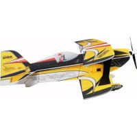
| Product type | Radio-controlled model airplane (Extra 330SC Indoor Edition) |
| Brand | Multiplex |
| Model | 214335 / Extra 330SC Indoor Edition |
| Wingspan | 845 mm |
| Overall length | 920 mm |
| Flying weight | 175 g |
| Number of channels | 4 |
| RC functions | Elevator, rudder, ailerons, motor |
| Flight time | Approximately 6 minutes |
| Motor | ROXXY C27-13-1800kV (included) |
| Speed controller | ROXXY BL Control 712 BEC |
| Recommended battery | ROXXY EVO LiPo 2 - 450B 30C with BID-Chip |
| Main material | EPP foam (ELAPOR) |
| Recommended minimum age | 14 years |
| Assembly | Assembly kit (Zacki-ELAPOR cyanoacrylate glue recommended) |
| Required tools | Zacki-ELAPOR glue, Phillips screwdriver, hobby knife, long-nose pliers, 320-grit sandpaper |
| Center of gravity | 100 mm behind the leading edge of the wing |
| Recommended control throws | Elevator: 80% EXPO, Ailerons and rudder: 60% EXPO |
| Maintenance | Check the condition of parts before each flight, clean with a dry cloth, store in a dry place away from moisture |
| Safety | Do not use by children under 14 years, keep away from children under 3 years (choking hazard), have insurance, follow the safety instructions detailed in the manual |
| Repairability | Spare parts available (references listed in the manual), repair possible with specific glues |
Frequently Asked Questions - 214335 MULTIPLEX
User questions about 214335 MULTIPLEX
0 question about this device. Answer the ones you know or ask your own.
Ask a new question about this device
Download the instructions for your Remote control toy in PDF format for free! Find your manual 214335 - MULTIPLEX and take your electronic device back in hand. On this page are published all the documents necessary for the use of your device. 214335 by MULTIPLEX.
USER MANUAL 214335 MULTIPLEX
This model is NOT A TOY in the usual sense of the term.
By operating the model the owner affirms that he is aware of the content of the operating instructions, especially those sections which concern safety, maintenance, operating restrictions and faults, and is capable of fulfilling these requirements.
This model must not be operated by any child under fourteen years of age. If a person below this age operates the model under the supervision of a competent adult who is acting as the child's guardian within the legal sense of the term, this individual is responsible for the implementation of the information in the OPERATING INSTRUCTIONS.
THE MODEL AND ASSOCIATED ACCESSORIES MUST BE KEPT OUT OF THE REACH OF CHILDREN UNDER THREE YEARS OF AGE! MODELS CONTAIN SMALL DETACHABLE PARTS WHICH MAY BE SWALLOWED BY CHILDREN UNDER THREE YEARS. CHOKING HAZARD!
All the warnings in the OPERATING INSTRUCTIONS must be observed whenever the model is operated. Multiplex Modellsport GmbH & Co. KG accepts no liability for loss or damage or any kind which occurs as a result of incorrect operation or misuse of this product, including the accessories required for its operation. This includes direct, indirect, deliberate and accidental loss and damage, and all forms of consequent damage.
Every safety note in these instructions must always be observed, as all the information contributes to the safe operation of your model. Use your model thoughtfully and cautiously, and it will give you and your spectators many hours of pleasure without constituting a hazard. Failure to operate your model in a responsible manner may result in significant property damage and severe personal injury. You alone bear the responsibility for the implementation of the operating instructions and the safety notes.
Approved usage
The model is approved exclusively for use within the modelling hobby. It is prohibited to use the model for any other purpose than that stated. The operator of the model, and not the manufacturer, is responsible for damage or injury of any kind resulting from non-approved use.
The model may only be operated in conjunction with those accessories which we expressly recommend. The recommended components have undergone thorough testing, are an accurate match to the model, and ensure that it functions safely. If you use other components, or modify the model, you operate it at your own risk, and any claim under guarantee is invalidated.
To minimise the risk when operating the model, please observe the following points:
- The model is guided using a radio control system. No radio control system is immune to radio interference, and such interference may result in loss of control of the model for a period of time. To avoid collisions, you must therefore ensure at all times that there is a wide margin of safety in all directions when operating your model. At the slightest sign of radio interference you must cease operating your model!
- Never operate your model until you have successfully completed a thorough check of the working systems, and carried out a range-check as stipulated in the instructions supplied with your transmitter.
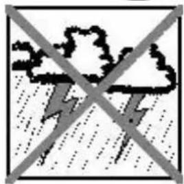
- The model may only be flown in conditions of good visibility. You can avoid being temporarily blinded by not flying towards the sun, or in other difficult light conditions.
- A model must never be operated by a person who is under the influence of alcohol, drugs or medication which have an adverse effect on visual acuity and reaction time.
- Only fly your model in conditions of wind and weather in which you are able to maintain full control of the model. Even when the wind is light, bear in mind that turbulence can form at and around objects which may have an effect on the model.
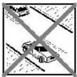
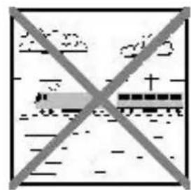
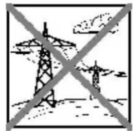
- Never fly in any location where you may endanger yourself of others, e.g. close to residential areas, overhead cables, open roads and railway lines.
- Never fly towards people or animals. You may think that flying low over other people's heads is proof of your piloting skill, but all it does is place others at unnecessary risk. It is in all our interests that you let other pilots know that this is what you think. Always fly in such a way that you do not endanger yourself or others. Bear in mind that even the best RC system in the world is subject to outside interference. No matter how many years of accident-free flying you have under your belt, you have no idea what will happen in the next minute.
Residual risks
Even if the model is operated in the correct manner, and you observe all safety aspects, there is always a certain residual risk.
For this reason it is mandatory to take out third-party liability insurance. If you join a club or flying association, insurance is usually available or included in the annual fee. Make sure that your insurance cover is adequate (i.e. that it covers powered model aircraft). Always keep your models and your radio control equipment in perfect order.
The following hazards may occur owing to the model's construction and type:
- Injury caused by the propeller: you must keep well clear of the area around the propeller from the moment that the battery is connected. Please bear in mind that objects in front of the propeller may be sucked into it, and objects behind the propeller may be blown away by it. The model may start moving when the propeller starts to turn. You must therefore position the model in such a way that it cannot move towards other persons if the motor should unexpectedly start running. When you are carrying out adjustment work involving the running motor, you must ensure that the model is always held securely by an assistant.
- Crash caused by pilot error: this can happen even to the best of pilots, so it is essential to fly exclusively in a safe environment; an approved model flying site and suitable insurance are basic essentials.
- Crash caused by technical failure or unnoticed damage in transit or in the workshop. A thorough check of the model before every flight is essential. However, you should also take into account at all times that material failures can and do occur. Never fly in a location where your model may damage or injure others.
- Keep within the stated operating limits. Excessively violent flying will weaken the airframe, and may result in sudden material failure, or may cause the model to crash during a subsequent flight due to "creeping" consequent damage.
- Fire hazard caused by electronic failure or malfunction. Store batteries safely, and always observe safety notes which apply to the airborne electronic components, the battery and the battery charger. Protect all electronic equipment from damp. Ensure that the speed controller and battery are adequately cooled.
The instructions which accompany our products must not be reproduced and / or published, in full or in part, in print or any electronic medium, without the express written approval of Multiplex Modellsport GmbH & Co. KG.
MULTIPLEX model kits are subject to constant quality checks throughout the production process, and we sincerely hope that you are completely satisfied with the contents of your kit. However, we would ask you to check all the parts before you start construction, as we cannot exchange components which you have already worked on. If you find any part is not acceptable for any reason, we will readily correct or exchange it. Just send the component to our Model Department. Please be sure to include the purchase receipt and a brief description of the fault.
We are constantly working on improving our models, and for this reason we must reserve the right to change the kit contents in terms of shape or dimensions of parts, technology, materials and fittings, without prior notification. Please understand that we cannot entertain claims against us if the kit contents do not agree in every respect with the instructions and the illustrations.
Caution!
Radio-controlled models, and especially model aircraft, are by no means playthings. Building and operating them safely requires a certain level of technical competence and manual skill, together with discipline and a responsible attitude at the flying field. Errors and carelessness in building and flying the model can result in serious personal injury and damage to property. Since we, as manufacturers, have no control over the construction, maintenance and operation of our products, we are obliged to take this opportunity to point out these hazards and to emphasise your personal responsibility.
Warning:
Like every aeroplane, this model has static limits. Steep dives and senseless manoeuvres inappropriate to the type may result in the loss of the aircraft. Please note: we will not replace the model in such cases. It is your responsibility to approach the airframe's limits gradually. It is designed for the power system recommended in these instructions, but is only capable of withstanding the flight loads if built exactly as described and if it is in an undamaged state.
Recommended equipment EXTRA 330SC Indoor Edition:
Article Number Quantity Description:
1-00012 1 Extra 330 SC Indoor Edition power set
112065 1 HS-65HB servo
112040 2 HS-40 servo
55808 1 RX-5 light M-LINK 2.4 GHz receiver
852727 1 Zacki ELAPOR 20 g, pack of 1
852728 1 Zacki ELAPOR super liquid 10g pack of 1
1-00016 1 ROXXY EVO LiPo 2 - 450B 30C with BID chip
Important note
This model is not made of Styrofoam™, and it is not possible to glue the material using white glue, polyurethane or epoxy; these adhesives only produce superficial joints, and simply break away under stress. Please be sure to use medium-viscosity cyano-acrylate glue exclusively, preferably Zacki ELAPOR® # 59 2727, which is optimised specifically for ELAPOR® particle foam. If you se Zacki ELAPOR® there is usually no need for cyano 'kicker' or activator. However, if you wish to use a different adhesive which requires the use of activator, please note that these materials are injurious to health, and should always be applied in the open air. Take care when handling all cyano-acrylate adhesives, as they harden in seconds, so don't get them on your fingers or other parts of the body. We strongly recommend the use of goggles to protect your eyes. Keep the adhesive out of the reach of children! For certain joints it is also possible to use hot-melt adhesive; the instructions indicate where this is the case.
Working with Zacki ELAPOR®
Zacki ELAPOR® has been developed specifically for glued joints in our models which consist of moulded ELAPOR® foam parts. Please observe the following points in order to obtain perfect joints:
- Avoid the use of activator. 'Kicker' significantly weakens the joint. We advise leaving joined parts for 24 hours to obtain maximum strength, particularly when the glued area is large.
- Activator should only be used for temporary, small-area joints ('tacking'). Spray a little activator on one surface, and allow it to air-dry for about thirty seconds.
To obtain maximum joint strength you should lightly sand the surface with 320-grit abrasive paper before applying glue.
Technical information EXTRA 330SC Indoor Edition:
Wingspan: 845 mm
Overall length: 920 mm
All-up weight: 175 g
Control channels: 4
RC functions: Elevator, rudder, aileron, throttle
Flight time: 6 min
Seite 10
A warm welcome to your new Multiplex Extra 330SC Indoor Edition.
You will require the following tools to build the model:
1 x Zacki Elapor # 85 2727
1 x Zacki® Elapor super liquid # 85 2728
Activator spray for CA adhesive
UHU®POR
Small cross-point screwdriver
Balsa knife
Pointed-nose pliers
1 sheet 320-grit abrasive paper
Before starting construction:
Check that all parts are present by comparing the kit contents with the Parts List on page 13.
To ensure that the airframe is free of warps we recommend building the model on a perfectly flat surface, cleaned carefully to avoid denting or scoring the components. It is essential to cover the surface with clear plastic film to prevent the parts becoming stuck to it. Unless expressly stated otherwise, please use Zacki®-Elapor CA (cyano-acrylate) adhesive for all joints on the model.
1. Preparing and assembling the model's horizontal components:
Prepare the flat building surface by cleaning it carefully, then cover it with clear plastic film. Lay the tailplane on the building board, top side up, and insert the 0.5 × 3 × 100 ~mm CFRP rectangular strips (26) in the slots. Run low-viscosity (thin) Zacki Elapor super liquid along the strips, then apply a little activator spray to cure the glued joints.
Fig. 1
The wings and tailplane should be glued to the fuselage centre section using UHU® POR. This is accomplished by applying the adhesive sparingly to the joint surfaces, leaving them to air-dry for about eight minutes, then pressing the parts together. Glue the CFRP rods in the wings and the fuselage centre section as described for the tailplane. The 0.8mm × 330mm and 0.8 × 370mm rods (16 & 17) overlap in the centre of each panel
Fig. 2
2. Preparing the lower fuselage section, gluing it to the centre section:
Glue the 0.8 × 530 mm CFRP rod (20) in the lower fuselage section. Glue the undercarriage support plates (43) and the L.H. and R.H. strut brackets in the positions shown. Take care not to apply too much adhesive: remember that CFRP rods have to pass through the holes later. Glue the tailskid in place using UHU®POR.
Fig. 3
Apply UHU®POR to the joint surfaces of the lower fuselage section and the centre section, and glue them together as described above. Check carefully that the parts are aligned correctly and exactly at right-angles to each other.
Fig. 4
3. Stiffening the fuselage and wings:
Cut the 0.8 × 500 mm CFRP rods (19) to the required
lengths, and glue them to the fuselage as shown to stiffen the structure. The undercarriage legs can also be glued to the fuselage at this stage; they consist of the 1.5 × 2.5 × 230 ~mm rectangular strips (30) and the 1.2 × 250 ~mm wing struts (22). Standard Zacki Elapor should be used for these joints.
Fig. 5
4. Installing the aileron servo and linkages:
Set the aileron servo (Hitec HS-65HB # 11 2065) to neutral (centre) using a servo tester or your radio control system, then fit the double-ended output lever (supplied with the servo) on the servo shaft. Locate the servo output lever (37) supplied in the kit, and screw it to the lever attached to the servo. Drill 1mm holes in the aileron servo output lever at the points where the pushrods will subsequently be connected. This part should face forward. Fix the servo in the appropriate recess by applying a small drop of Zacki to each servo mounting lug.
Fig. 6
Glue the L.H. and R.H. aileron horns (33 & 34) in the slots in the ailerons. The pushrods are assembled as shown in the drawing: one end of the pushrod is completed by gluing it into an M2 x 20 mm threaded coupler (48), and screwing a clevis (46) on the coupler; grip the threaded coupler in a pair of pliers while you do this. Use a small pair of pliers to press the linkage pins (47) through the clevises to connect them to the aileron horns, then slip the pushrods into the clevises. Measure the correct pushrod length to the servo, then glue the clevises to the pushrods. The final pushrod length can now be adjusted by screwing the clevises in or out on the threaded couplers. Ensure that both ailerons are exactly horizontal when the servo is at neutral (centre). The pushrods can now be connected to the servo output lever by engaging the linkage pins.
Fig. 7
5. Fitting the undercarriage fairings and wheels:
Sand the bottom end of the undercarriage legs horizontal, so that the model stands straight. Now glue the axle mounting brackets (38) and the 1.5 × 25mm CFRP axles (24) to the legs. Slip the spacer rings (44) and the wheels (31) onto the axles, together with the wheel spat holders (40). Glue the wheel spats to the holders and the spacer rings, taking care to leave the wheels free to rotate.
Apply UHU® POR sparingly to the undercarriage fairings and glue them to the undercarriage legs.
Fig. 8
6. Installing the side force generators and elevator linkages:
Use a servo tester or your radio control system to set the rudder and elevator servos (Hitec HS-40 # 11 2040) to centre (neutral), and attach the large double-ended output levers (supplied with the servos) to the output shafts. Only one end of the lever is needed; cut off the other end. Locate the second hole from the centre of the servo output lever and drill it out to 1mm .Glue the elevator servo in the aperture by applying a small drop of Zacki at each mounting lug. Now glue the elevator horn in the elevator. Thread six pushrod guides onto a 1.0 × 500mm CFRP rod (23), then glue the guides in the slots in the underside of the fuselage.
Complete the linkages as described for the ailerons, but in this case use M2 x 14 mm threaded couplers. At the other end of the pushrod fit an adapter sleeve to ensure that the clevis is a good fit on the CFRP rod. Take care to produce sound glued joints between all the linkage components. Slit the side force generators to allow them to fit on the wing and tailplane, then glue them in place as shown.
Fig. 9
7. Adding the upper fuselage section and the rudder linkage:
Glue the upper fuselage section to the model, then install the rudder servo and linkage using the procedure already described for the elevator pushrod. Glue a 3 × 0.5 × 100 mm CFRP reinforcement (26) and the rudder horn (35) to the rudder. The rudder can now be glued to the fuselage using UHU®POR before completing the rudder linkage. Glue the motor bulkhead 32 permanently to the front end of the fuselage using Zacki.
Figs. 10 & 11
8. Installing the RC components:
Screw the motor (ROXXY C27-13-1800kV # 1-00018) to the front face of the motor bulkhead, and attach the speed controller (ROXXY BL Control 712 BEC # 318971) to the underside of the fuselage using hook-and-loop tape. The same method is used to fix the receiver and battery to the fuselage. Since the battery-mounting tape is subject to considerable stress, it is advisable to rub a little UHU® POR into the EPP foam at the mounting position, and allow the adhesive to air-dry for ten minutes to improve the tape's adhesion.
9. Centre of Gravity, control surface travels:
The model should balance at a point 100mm back from the wing leading edge, measured close to the fuselage. The control surface travels should be chosen to suit the pilot's personal preference, but we recommend adding about 80% EXPO on elevator and 60% EXPO on aileron and rudder.
15. Safety
Safety is the First Commandment when flying any model aircraft. Third party insurance is mandatory. If you join a model club, suitable cover will usually be available through the organisation. It is your personal responsibility to ensure that your insurance is adequate (i.e. that its cover includes powered model aircraft). Make it your job to keep your models and your radio control system in perfect order at all times. Check and observe the correct charging procedure for the batteries you are using. Make use of all sensible safety systems and precautions which are advised for your system. An excellent source of practical accessories is the MULTIPLEX main catalogue or our website wwwultiplex.de
MULTIPLEX products are designed and manufactured exclusively by active modellers for practising modellers. Always fly with a responsible attitude. You may think that flying low over other people's heads is proof of your piloting skill; others know better. The real expert does not need to prove himself in such childish ways. Let other pilots know that this is what you think too, as it is in all our interests. Always fly in such a way that you do not endanger yourself or others. Bear in mind that even the best RC system in the world is subject to outside interference.
No matter how many years of accident-free flying you have under your belt, you have no idea what will happen in the next minute.
Before every flight, check that the battery, the wings and the tailplane are attached and firmly seated. Check in turn that each control surface is operating correctly!
We - the MULTIPLEX team - hope you have many hours of pleasure building and flying your new model.
MULTIPLEX Modellsport GmbH &Co.KG
Part No. Qty Description Material Dimensions
1 1 Extra 330SC Indoor building instructions Paper DIN A4
2 1 Model complaint form Paper DIN A5
3 1 Upper fuselage section EPP Ready made
4 1 Lower fuselage section EPP Ready made
5 1 Fuselage centre section EPP Ready made
61 L.H. wing EPP Ready made
71 R.H. wing
81 Tailplane
91 Fin
10 2 Wing side force generator
11 2 Tailplane side force generator
12 1 L.H. wheel spat
13 1 R.H. wheel spat
14 2 Undercarriage fairing
15 1 Tailskid
16 2 Carbon fibre rod
17 2 Carbon fibre rod
18 2 Carbon fibre rod
19 4 Carbon fibre rod
20 1 Carbon fibre rod
21 2 Carbon fibre rod
22 4 Carbon fibre rod
23 2 Carbon fibre rod (pushrods)
24 2 Carbon fibre rod (wheel axles)
25 2 Carbon fibre rod (pushrods)
26 5 Rectangular-section carbon strip
27 1 Rectangular-section carbon strip
28 1 Rectangular-section carbon strip
29 2 Rectangular-section carbon strip
30 2 Rectangular-section carbon strip
31 2 Wheel
32 1 Motor bulkhead
33 1 L.H. aileron horn
34 1 R.H. aileron horn
35 1 Rudder horn
36 1 Elevator horn
37 1 Aileron servo output lever
38 2 Axle mounting bracket
39 12 Pushrod guide
40 2 Wheel spat holder
41 1 L.H. strut bracket
42 1 R.H. strut bracket
43 2 Undercarriage support plate
44 2 Wheel spacer ring
45 2 Adapter sleeve
46 10 Clevis
47 10 Clevis pin
48 2 Threaded coupler
49 3 Threaded coupler
EPP Ready made
EPP Ready made
EPP Ready made
EPP Ready made
EPP
Ready made
EPP Ready made
EPP Ready made
EPP Ready made
EPP Ready m
CFRP 0.8 日 x330mm
CFRP 0.8 日 x370mm
CFRP 0.8Øx470mm
CFRP 0.8 日 x500mm
CFRP 0.8 x530mm
CFRP 1.0 日 x 140 mm
CFRP 1.20x250mm
CFRP 1.0 日 x500mm
CFRP 1.50x25mm
CFRP 1.50x120mm
CFRP 3 × 0.5 × 100 ~mm
CFRP 3 × 0.5 × 140 ~mm
CFRP 3 × 0.5 × 330 ~mm
CFRP 3 × 0.5 × 660 ~mm
CFRP 1.5× 2.5× 230mm
Plastic 27 mm Ø
Plastic Ready made
Plastic Ready made
Plastic Ready made
Plastic Ready made
Plastic Ready made
Plastic Ready made
Plastic Ready made
Plastic Ready made
Plastic Ready made
Plastic Ready made
Plastic Ready made
Plastic Ready made
Plastic 4mm0
Plastic 20x5mm
Plastic Ready made
Brass 10x5mm
Brass M2 x 20 mm
Brass M2 x 14 mm
55808 1 RX-5 light M-LINK 2.4 GHz receiver
852727 1 Zacki ELAPOR 20 g, pack of 1
852728 1 Zacki ELAPOR super liquid 10g pack of 1
1-00016 1 ROXXY EVO LiPo 2 - 450B 30C with BID chip
Nota importante
Overall length: 920 mm
All-up weight: 175 g
Control channels: 4
RC functions: Elevator, rudderatae, ran, rotleron, throttle
Flight time: 6 min
Seite 24
Overall length: 920 mm
All-up weight: 175 g
Control channels: 4
RC functions: Elevator, rudder, aileron, throttle
Flight time: 6 min