DB36600XP92V - Cooker BERTAZZONI - Free user manual and instructions
Find the device manual for free DB36600XP92V BERTAZZONI in PDF.
Questions des utilisateurs sur DB36600XP92V BERTAZZONI
0 question sur cet appareil. Repondez a celles que vous connaissez ou posez la votre.
Poser une nouvelle question sur cet appareil
Download the instructions for your Cooker in PDF format for free! Find your manual DB36600XP92V - BERTAZZONI and take your electronic device back in hand. On this page are published all the documents necessary for the use of your device. DB36600XP92V by BERTAZZONI.
USER MANUAL DB36600XP92V BERTAZZONI
(GB) INSTRUCTIONS FOR THE INSTALLATION, MAINTENANCE
pag. 2 AND USE OF FIXED HOBS WITH GAS OR MIXED SUPPLY
DROP IN (TYPE P92/P92V)
(FR) INSTRUCTIONS POUR L'INSTALLATION, L'ENTRETIEN ET
page.7 L'UTILISATION DES TABLES DE CUISSON ENCASTRABLES
GAZ ET MIXTES
DROP IN (MODELE P92/P92V)
(NL) INSTRUCTIES VOOR INSTALLATIE, ONDERHOUD EN
pag. 12 GEBRUIK VAN INGEBOUWDE GASKOOKPLATEN (TYPE P92/P92V)
(GB)
READ THE INSTRUCTION BOOKLET BEFORE INSTALLING AND USING THE APPLIANCE.
These instructions are valid only for those countries which are indicated by their identification symbol on the front cover of the instruction booklet and on the label on the appliance.
The manufacturer cannot be held responsible for any damage to things or persons caused by an incorrect installation or by incorrect use of the appliance.
The manufacturer cannot be held responsible for any inaccuracies due to errors in printing or writing contained in this booklet. The appearance of the figures shown is also only approximate.
The manufacturer reserves the right to make changes to his products when it is considered necessary and useful without effecting the essential features regarding safety and function.
INDEX:
TECHNICAL MANUAL FOR THE INSTALLER . 2
Inserting the hob . pag. 2
Fixing the hob - Advice about installation . pag. 3
Ventilation and airng of the premises - Connection to the gas supply . pag. 3
Adaptation to different types of gas
Regulation of the burners . pag. 4
Connection to the electricity supply . 4
MAINTENANCE OF THE APPLIANCE - Replacing parts. pag. 4
USE AND MAINTENANCE MANUAL . . . . . . . . . . . . . . . . . . . . . . . . . . . . . . . . . . . . . . . . . . . . . . . .
Description of types of hobs . 5
Use of the burners . 5
Cleaning of the appliance . . . . . . . . . . . . . . . . . . . . . . . . . . . . . . . . . . . . . . . . . . . . . . . .
Figures . 1
Electrical Diagram . pag. 14-15
THIS APPLIANCE HAS BEEN DESIGNED FOR NON PROFESSIONAL USE IN HOUSEHOLDS.
TECHNICAL MANUAL FOR THE INSTALLER
INFORMATION FOR THE INSTALLER
The installation, all regulations, changes and maintenance referred to in this part must only be carried out by qualified staff. A wrong installation can cause damage to persons, animals or things which the manufacturer cannot be held responsible for. The safety and automatic regulation devices on the appliances can only ever be changed by the manufacturer or by the supplier which has been authorised to do so.
INSERTING THE HOB
When you have removed the various adjustable parts from their internal and external packaging, check that the hob is intact. If you are in doubt do not use the appliance and contact the qualified staff.
The parts which make up the packaging ( polystyrene, bags, boxes, nails etc.), are dangerous objects and must be kept out of children's reach.
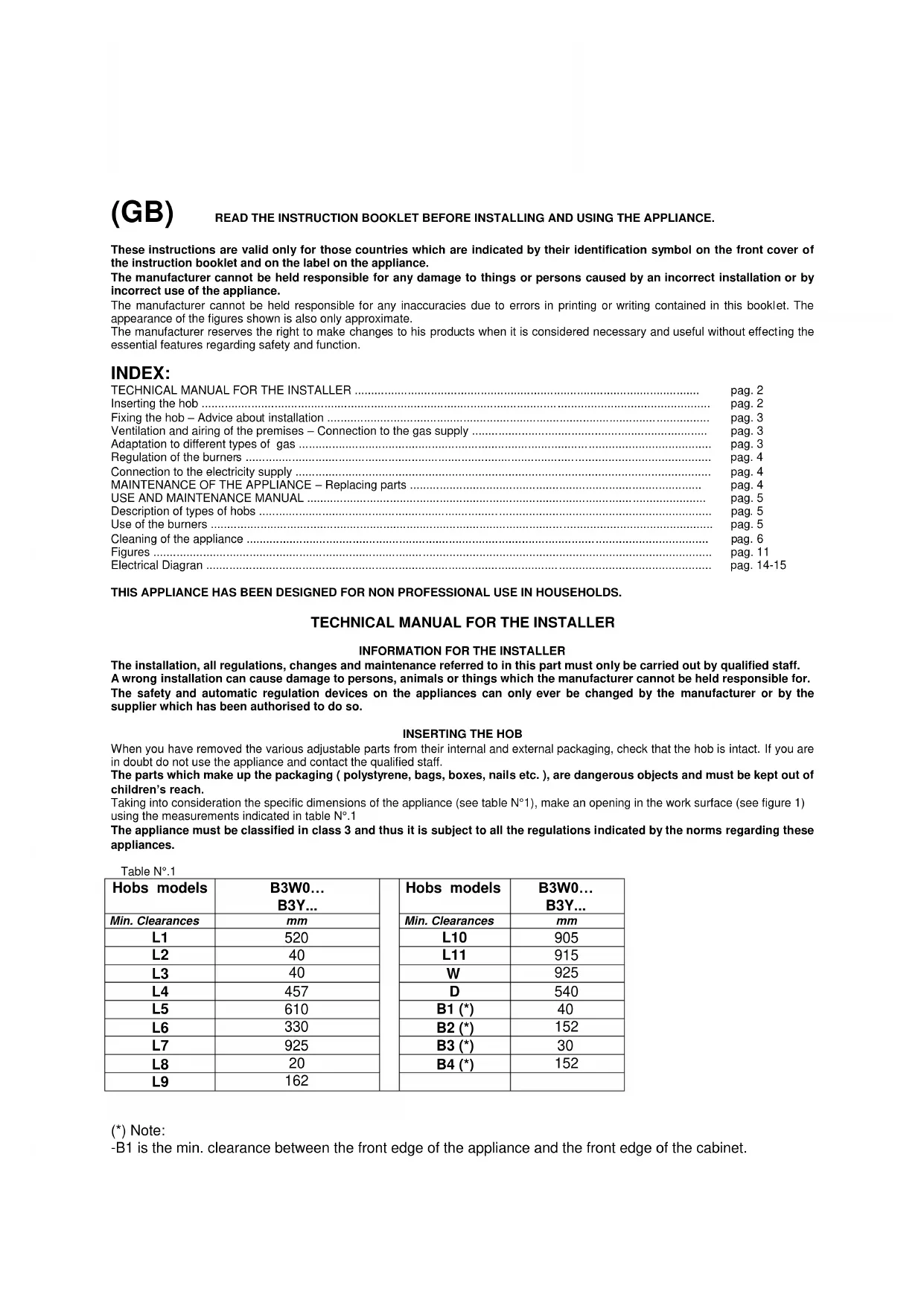
Taking into consideration the specific dimensions of the appliance (see table N°1), make an opening in the work surface (see figure 1) using the measurements indicated in table N°1
The appliance must be classified in class 3 and thus it is subject to all the regulations indicated by the norms regarding these appliances.
Table N.1
| Hobs models | B3W0... B3Y... | Hobs models | B3W0... B3Y... | |
| Min. Clearances | mm | Min. Clearances | mm | |
| L1 | 520 | L10 | 905 | |
| L2 | 40 | L11 | 915 | |
| L3 | 40 | W | 925 | |
| L4 | 457 | D | 540 | |
| L5 | 610 | B1 (*) | 40 | |
| L6 | 330 | B2 (*) | 152 | |
| L7 | 925 | B3 (*) | 30 | |
| L8 | 20 | B4 (*) | 152 | |
| L9 | 162 |
(*) Note:
-B1 is the min. clearance between the front edge of the appliance and the front edge of the cabinet.
-B2 and B4 are the min. clearance between the left/right side edge of the appliance and the side wall (if present).
-B3 is the min. clearance between the back edge of the appliance and the back wall.
ATTACHING THE HOTPLATE
To prevent liquids from leaking accidentally into the underlying storage space, the appliance is equipped with a special gasket. To apply this gasket, carefully follow the instructions in Fig. 3. Lay out the protective sealing strips along the edges of the opening in the bench top and carefully overlap the strip end. (See Fig. 3). insert the hotplate into the bench top opening. With a screwdriver assemble the brackets A to the hotplate bottom by means of the screws B. (See Fig. 4). Slide the hooks into position and secure them with the screws.
Trim the part of the sealing strips which extend beyond the hotplate base
IMPORTANT INFORMATION CONCERNING THE INSTALLATION OF THE APPLIANCE
We inform the installer that this hob is of the Y type and thus it can be installed by itself, in an isolated position or inserted between two kitchen units or between one kitchen unit and a wall. Furthermore the back wall and surrounding surfaces must resist a temperature of 65K .
To prevent the plastic layer which covers the kitchen unit from ungluing, the glue used to join the two surfaces together must resist temperatures of up to 150^
The installation of the appliance must be carried out according to the norms in force of the country concerned and the appliance must be installed in a well ventilated place.
This appliance is not equipped with devices to remove the products of combustion. The appliance must therefore be connected following the norms for installation mentioned above. Special attention must be paid to the information below regarding aeration and ventilation of the premises.
VENTILATION OF THE PREMISES
To guarantee that the appliance works correctly it is necessary that the place where the appliance is installed is continuously ventilated. The volume of the premises must not be less than 25m^3 and the quantity of air needed must be based on the regular combustion of gas and on the ventilation of the premises. The natural flow of air will take place through permanent openings made in the wall of the premises to be ventilated: these openings will be connected to the outside and must have a minimum section of 100cm^2 (see Fig. 6). These openings must be made in such a way that they cannot be obstructed.
POSITION AND VENTILATION
The cooking appliances that use gas must always remove the products of combustion via a hood linked to chimneys, chimney flues or via a direct connection to the outside (see Fig. 6A). If it is not possible to fit a hood it is possible to use a fan, fitted on the window or facing directly outside, which operates when the appliance is in use. (see Fig. 6B). In this way the norms in force of the country concerned regarding the ventilation of premises are strictly followed.
CONNECTING THE APPLIANCE TO THE GAS SUPPLY
Before connecting the appliance to the gas supply you first need to remove the plastic protective plug for the gas supply which is inserted under pressure in the gas inlet connection. To remove the plug simply unscrew it.
Then make sure that the details shown on the label on the lower part of the case are compatible with those of the gas supply. A label on the last page of this manual and on the lower part of the case indicates the conditions for regulating the appliance: type of gas and pressure used.
IMPORTANT: This appliance must be installed in accordance with the norms in force of the country concerned and it must only be used in a well-ventilated place.
ATTENTION: Remember that the gas inlet connection for the appliance is threaded 1/2 gas cylindrical male in accordance with the norms UNI-ISO 228-1. (Fig. 5)
ADAPTING TO DIFFERENT TYPES OF GAS
Before carrying out any maintenance work, disconnect the appliance from the gas and electric supply. - CHANGING THE NOZZLES FOR USE WITH OTHER TYPES OF GAS:
To change the nozzles of the burners use the following procedure:
Lift up the burners and unscrew the nozzles (Fig. 9) using an adjustable spanner of 7mm and change the nozzles with those designed for the new gas supply according to the information given in TABLE N° 2 shown below.
ATTENTION: After carrying out the changes described above, the technician must put the label corresponding to the new gas supply on the appliance to take the place of the old label. This label is found in the bag containing spare nozzles.
TABLE N2: Adapting to different types of gas APPLIANCE CATEGORY: II2H3+
| Burner | Type of Gas | Pressure | Nozzle diameter | Nominal Charge | Reduced Charge | Diameter by-pass 1/100mm | ||||
| mbar | 1/100mm | g/h | l/h | Kw | kcal/h | kw | kcal/h | safety | ||
| Auxiliary | Natural G20 | 20 | 77 | - | 95 | 1 | 860 | 0,3 | 258 | 27 |
| Butane G30 | 28-30 | 50 | 73 | - | 1 | 860 | 0,3 | 258 | 27 | |
| Propane G31 | 37 | 50 | 71 | - | 1 | 860 | 0,3 | 258 | 27 | |
| Semi-Rapid | Natural G20 | 20 | 101 | - | 167 | 1,75 | 1505 | 0,44 | 378 | 31 |
| Butane G30 | 28 | 66 | 127 | - | 1,75 | 1505 | 0,44 | 378 | 31 | |
| Propane G31 | 37 | 66 | 125 | - | 1,75 | 1505 | 0,44 | 378 | 31 | |
| Rapid | Natural G20 | 20 | 129 | - | 286 | 3 | 2580 | 0,75 | 645 | 42 |
| Butane G30 | 28 | 87 | 218 | - | 3 | 2580 | 0,75 | 645 | 42 | |
| Propane G31 | 37 | 87 | 214 | - | 3 | 2580 | 0,75 | 645 | 42 | |
| Dual | Natural G20 | 20 | In 70 | - | 476 | 5 | 4300 | 0,48 | 413 | In 34 |
| Out 2x110 | Out 65 | |||||||||
| Butane G30 | 28 | In 46 Out 2x69 | 334 | - | 4,6 | 3956 | 0,48 | 413 | In 34 Out 65 | |
| Propane G31 | 37 | In 46 Out 2x69 | 338 | - | 4,6 | 3956 | 0,48 | 413 | In 34 Out 65 | |
REGULATION OF BURNERS:
Regulation of the "MINIMUM" on the burners
To regulate the minimum on the burners carry out the following procedure indicated below:
1) Turn on the burner and put the knob onto position MINIMUM (small flame).
2) Remove the knob (Fig. 10) of the tap which is set for standard pressure. The knob is found on the bar of the tap itself.
3) Beside the tap bar on the work top, use a small screwdriver that fits the screw (gold) found on the lower part of the tap (auxiliary, semirapid, rapid Fig. 10 (dual fig.11) and turn the fixing screw to the right or left until the flame of the burner is regulated in the most suitable way to MINIMUM.
4) Make sure that the flame does not go out when changing the position quickly from MAXIMUM to the MINIMUM position.
ATTENTION: The regulation described above can be carried out only with burners using natural gas, while with burners using propane gas the screw must be fully screwed in, in a clockwise direction.
CONNECTION OF THE APPLIANCE TO THE ELECTRICITY SUPPLY:
Connection to the electricity supply must be carried out according to the norms and indications of the law in force.
Before carrying out the connection check that:
- The electric charge of the system and the sockets are suitable for the maximum power of the appliance (see label on the lower part of the case).
- The socket or system is equipped with an efficient earth connection according to the norms and indications of the law currently in force. No responsibility can be held if these indications are not respected.
When the connection to the electricity supply is made with a socket.
Fit onto the electric cable a standard plug ( if it is not provided ) which is appropriate for the charge indicated on the label. Connect up the wires according to the diagram in Fig. 12 taking care to respect the corresponding pairs listed below:
letter L (phase) = brown coloured wire;
letter N (neutral) = blue coloured wire;
symbol" earth = green-yellow coloured wire;
-
The electric cable must be positioned so that it cannot reach a temperature of over 75K at any point.
-
Do not use reducers, adapters or shunts for the connection as they could cause false contacts and subsequent dangerous overheating.
When the connection is made directly with the electricity supply:
-
Place a single-pole switch between the appliance and the electricity supply. The switch must be of a suitable charge for the appliance with a minimum opening between the contacts of 3mm .
-
Remember that the earth wire must not be interrupted by the switch.
- Alternatively the electrical connection can also be protected by a differential switch of high sensitivity.
- You are strongly advised to fix the special yellow-green earth wire to an efficient earthing system
ATTENTION:
The appliance conforms to the EEC indication 90/396 regarding gas cooking appliances for domestic use.
All our appliances are designed and produced according to the European norms EN 60 335-1 and EN 60 335-2-6 and additional relative amendments. The appliances conform with the indications of the European Low Tension Directive 73/23 and 93/68 as well as conforming with the indications of the European directive 89/336 regarding electromagnetic compatibility.
Before carrying out any maintenance work, disconnect the appliance from the gas and electric supply.
To replace different components such as burners, taps and electrical parts you must take out the hob from the kitchen unit by releasing the fixing hooks, unscrew the fixing screws of the burners on the work top, unscrew the fixing nuts of the electric plates which are visible on the lower part of the hob and remove the worktop in order to carry out the replacement of the defective parts.
NOTE: If the taps need replacing you also need to unscrew the two fixing screws of the gas ramp at the bottom of the hob which are found on the upper part of the latter.
For appliances equipped with automatic "ON" switches you must dismantle the "ON" switch chain before replacing the taps.
You are advised to change the seal on the tap every time you replace a tap in order to ensure a perfect hold between the body and ramp.
WARNING: The electric cable which is provided with the appliance is connected to the appliance with a type X connection (in accordance with the norms EN 60335-1, EN 60335-2-6 and successive variations) and thus can be replaced with the same type of cable as that installed without using special tools.
In the event of wear or damage to the mains cable, replace it following the indications shown below.Type/ section of mains cable H05RR-F 3x0,75 mm2
WARNING: If you replace the electric mains cable the installer must have the earth conductor about 2cm longer than the phase conductors and must also take heed of the warnings regarding electric connection.
Oilling the taps: (This must be carried out by qualified staff from a technical assistance centre)
If a tap becomes difficult to move you must oil the tap, without delay, following the instructions given below:
1) Dismantle the main part of the tap by unscrewing the two screws that can be found on the bar of the tap itself. (Fig. 13)
2) Take out and clean the holding cone and its setting with a cloth soaked in diluent.
3) Oil the cone lightly with the special oil.
4) Insert the cone, move it a few times, take it out again, remove the excess oil and make sure that the areas where the gas flows are not obstructed.
5) Reassemble all the pieces in the reverse order to that followed for the dismantling and check that the tap is working properly.
USE AND MAINTENANCE MANUAL
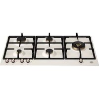
DESCRIPTION OF HOBS
Descriptions
DESCRIPTEV CAPTION FOR HOB DESCRIPTION OF HOBS
- Small Burner
Model 5 Burner Fig. 14 - Medium burner
Model 6 Burner Fig. 15 - Rapid burner
- Dual burner
- Front left side burner control knob
- Front right side burner control knob
- Rear right side burner control knob
- Rear left side burner control knob
- Central burner control knob
- Front central side burner control knob
- Central rear side burner control knob
CAPTION FOR ELECTRICAL DIAGRAM
(Diagrams fig. 16 fig.17)
1 Electric panel
2 Lighter button
3 Ignition device
4 Lighting plugs
L Brown (phase)
N Blue (neutral)
USE OF THE BURNERS
On the control panel above every knob there is a diagram which indicates which burner the knob in question refers to. The burners can be turned on in several ways according to the type of appliance and its individual features:
-
Manual "On" switch (this is always possible even if the electric current is cut off): Turn the knob corresponding to the selected burner in an anticlockwise direction so that the knob is at MAXIMUM (this corresponds to a large flame) and then put a lit match to the burner.
-
Electric "On" switch: Turn the knob corresponding to the selected burner in an anticlockwise direction so that the knob is at MAXIMUM (this corresponds to a large flame) and then press the lighter button and let it go as soon as the burner is alight..
-
Automatic Electric "On" switch: Turn the knob corresponding to the selected burner in an anticlockwise direction so that the knob is at MAXIMUM (this corresponds to a large flame) and then press in the knob. Let it go as soon as the burner is alight.
-
"On " switch for burners with safety device ( thermocouples ): Turn the knob corresponding to the selected burner in an anticlockwise direction so that the knob is at MAXIMUM (this corresponds to a large flame) and then use one of the lighting devices described above. When the burner is lit keep the knob pressed in for about 10 seconds in order to allow the flame to heat up the thermocouple. If the burner goes out when letting the knob go, repeat the operation all over again.
-
Use of the Dual burner (Fig.18)
This model controls both the central and the external crown of the burner with just one valve.
To ignite the central crown and the external crown of the burner, press and turn the knob to the maximum delivery position 1 and hold it down until ignition; in this position both the internal and the external flame are at maximum.
Turn the knob to position 2 to have the external crown at minimum and the internal crown at maximum flame
Turn the knob to position 3 to have the internal crown at maximum and the external crown off. Turn the knob to position 4 to have the internal crown at minimum and the external crown off.
N.B.: You are advised not to try and light a burner if its flame divider is not correctly in place.
Advice for the best use of the burners:
- Use suitable pans for each burner (see tab. n° 4 and Fig. 19).
- When boiling point is reached turn the knob on to MINIMUM.
- Always use pans with a lid.
TABLE N°4:Recommended pan diameters
| BURNER | PAN DIAMETERS recommended (cm.) |
| Small | 9 - 14 |
| Medium | 14 - 26 |
| Large | 18 - 26 |
| Dual | 22 - 26 |
ATTENTION: use containers with a flat bottom
ATTENTION: If there is no electric current you can light the burners with matches.
Lighting the burners with safety thermocouples can only be carried out when the knob is on MAXIMUM (large flame). When cooking food with oil or fat which can easily set alight, the user must not leave the appliance.
Do not use sprays near the appliance when it is in use. When using the burners make sure that the pan handles are in the correct position. Keep children away. If the hob has a lid, before closing it, make sure that the surrounding work surface is cleaned of any food that has been left there.
NOTE: The use of a gas cooking appliance produces heat and humidity in the place where it is installed. Therefore you need to ensure that the place is well ventilated, keeping clear the natural ventilation openings (Fig. 6) and using the mechanical ventilation device/ flue or electric fan ( Fig. 6A and 6B ). Intensive or prolonged use of the appliance may require additional entilation such as by opening a window or an increased ventilation efficiency obtained by increasing the power of the mechanical ventilators if it is present.
CLEANING OF THE APPLIANCE
Before carrying out any cleaning operation disconnect the appliance from the electric mains and turn off the main tap which supplies the appliance with gas.
Cleaning the worktop: Periodically the burner heads, enamelled steel grills, enamelled lids and flame dividers must be cleaned with warm soapy water, rinsed and dried well.
Any liquid which overflows from the pan must always be removed with a cloth.
If opening or closing any tap is difficult do not force it but ask for an urgent check from the technical assistant.
Cleaning of the enamelled parts: To maintain the features of the enamelled parts they must be cleaned frequently with soapy water. Never use abrasive powders. Avoid leaving acid or alkaline substances on the enamelled parts (vinegar, lemon juice, salt, tomato juice etc.) and washing the enamelled parts when they are still warm.
Cleaning of the stainless steel parts: Clean the parts with soapy water and then dry them with a soft cloth. The shininess is maintained by periodically cleaning with the special products normally available on the market. Never use abrasive powders.
Cleaning of the burner flame dividers: as they are not fixed, the flame dividers can be cleaned by simply removing them and cleaning with soapy water. After drying them well and checking that the holes are not blocked, put them back into their correct position.
(FR) (BE)
LISEZ ATTENTIVEMENT CETTE NOTICE AVANT D'INSTALLER ET D'UTILISER L'APPAREIL.
lettler L (phase) = fil marron,
lettre N (neutre) = fil bleu,
symbole" 1一 " terre = fil jaune-vert.