PR1PROCH94I1EXT - Cooker BERTAZZONI - Free user manual and instructions
Find the device manual for free PR1PROCH94I1EXT BERTAZZONI in PDF.
Download the instructions for your Cooker in PDF format for free! Find your manual PR1PROCH94I1EXT - BERTAZZONI and take your electronic device back in hand. On this page are published all the documents necessary for the use of your device. PR1PROCH94I1EXT by BERTAZZONI.
USER MANUAL PR1PROCH94I1EXT BERTAZZONI
Dear Customer, Many thanks for choosing the quality of Bertazzoni appliances for your home. My family has been building cookers since way back in 1882 and has won a sound reputation for the excellence of its engineering, springing from its passion for good food. Today, our products offer exclusive, typically Italian design and outstanding technology. Our mission is to construct appliances that work perfectly and give their users complete satisfaction. We respond to our customers’ demands by creating beautifully styled products. Our appliances are also versatile and agile, so cooking becomes a real pleasure. This manual will help you to use and care for a Bertazzoni product in the safest, most efficient way, to ensure that it will give you the greatest satisfaction for many years to come. I hope you will be completely pleased with it! Paolo Bertazzoni ChairmanVALIDITY OF USER MANUAL This user manual is valid for the following product codes:
- EXPIRY OF THE WARRANTY p. 95
- SERVICE p. 96
- CUSTOMER SERVICE p. 96
- CONVENTIONAL WARRANTY CERTIFICATE: what do I need to do? p. 96
- ANOMALIES AND MALFUNCTIONS: who do I contact? p. 96
- FINDING YOUR NEAREST SERVICE CENTRE p. 96
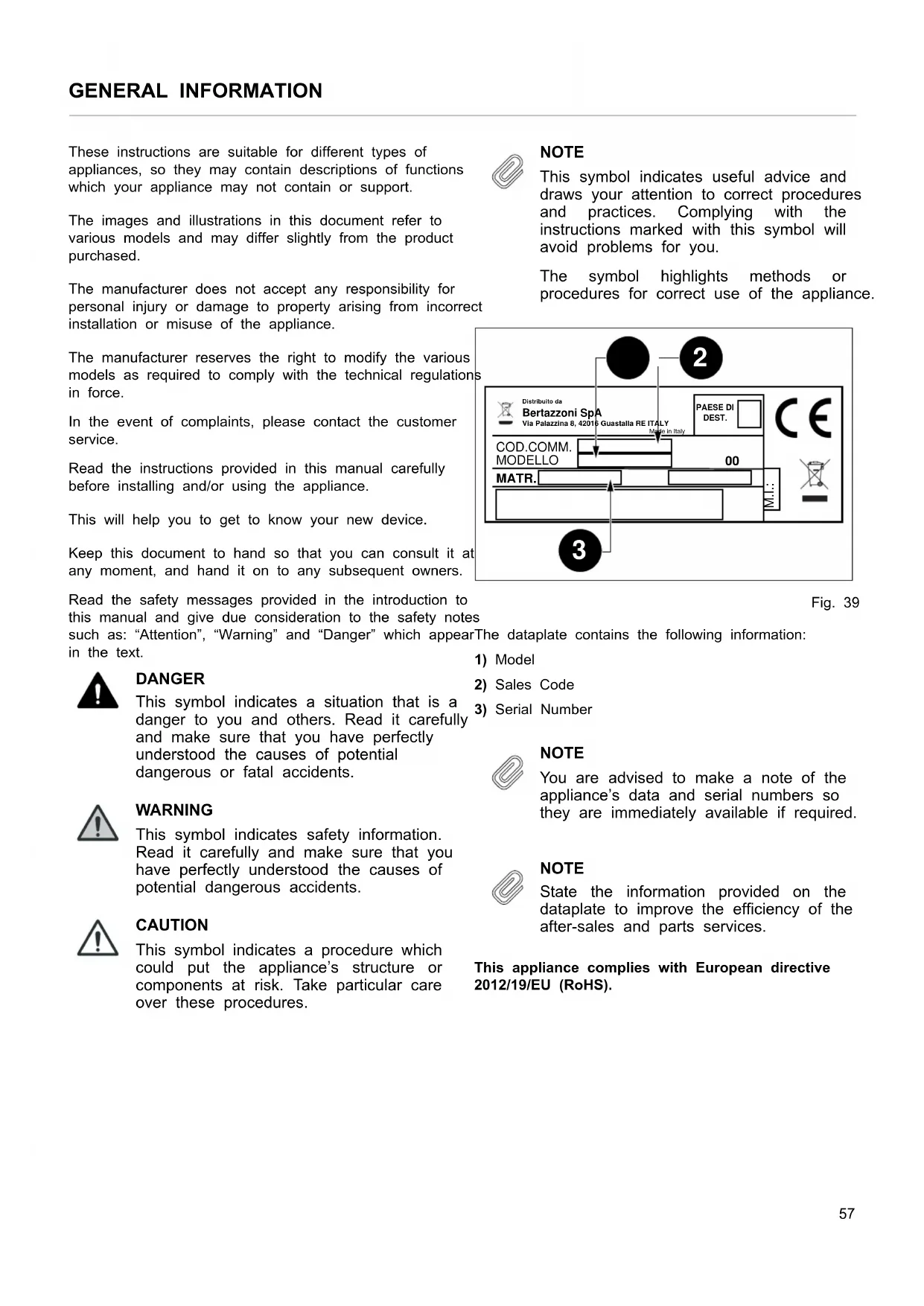
- PRODUCT MODEL: where can I find it? GENERAL INFORMATION These instructions are suitable for different types of appliances, so they may contain descriptions of functions which your appliance may not contain or support. The images and illustrations in this document refer to various models and may differ slightly from the product purchased. The manufacturer does not accept any responsibility for personal injury or damage to property arising from incorrect installation or misuse of the appliance. The manufacturer reserves the right to modify the various models as required to comply with the technical regulations in force. In the event of complaints, please contact the customer service. Read the instructions provided in this manual carefully before installing and/or using the appliance. This will help you to get to know your new device. Keep this document to hand so that you can consult it at any moment, and hand it on to any subsequent owners. Read the safety messages provided in the introduction to this manual and give due consideration to the safety notes such as: “Attention”, “Warning” and “Danger” which appear in the text. DANGER This symbol indicates a situation that is a danger to you and others. Read it carefully and make sure that you have perfectly understood the causes of potential dangerous or fatal accidents. WARNING This symbol indicates safety information. Read it carefully and make sure that you have perfectly understood the causes of potential dangerous accidents. CAUTION This symbol indicates a procedure which could put the appliance’s structure or components at risk. Take particular care over these procedures. NOTE This symbol indicates useful advice and draws your attention to correct procedures and practices. Complying with the instructions marked with this symbol will avoid problems for you. The symbol highlights methods or procedures for correct use of the appliance. Fig. 39 The dataplate contains the following information: p. 96
NOTE You are advised to make a note of the appliance’s data and serial numbers so they are immediately available if required. NOTE State the information provided on the dataplate to improve the efficiency of the after-sales and parts services. This appliance complies with European directive 2012/19/EU (RoHS). COD.COMM. Via Palazzina 8, 42016 Guastalla RE ITALYMade in ItalyBertazzoni SpAPAESE DIDEST. Distribuito da MODELLO 220-240V~/380-415V3N~ 50/60Hz 11100 W (INDUCTION 7400W) AXOVJZREXE. VAR M.I.:
57GENERAL INFORMATION This appliance is tagged in accordance with European directive 2012/19/EC regarding waste electrical and electronic equipment (WEEE). This directive contains the regulations governing the collection and recycling of decommissioned appliances throughout the European Union. The symbol of a waste bin with a cross over it which appears on the product indicates that Waste Electrical and Electronic Equipment (WEEE) must not be thrown away with ordinary urban waste but must be disposed of separately, so it can undergo special processing to enable its reuse or specific treatment for safe removal and disposal of any substances harmful to the environment and extraction of raw materials which can be recycled. Therefore, WEEE must be delivered to Recycling Centres run by Municipal Authorities or Waste Management Companies. What’s more, when a new appliance is purchased WEEE can be consigned to the retailer, who is obliged to take it back free of charge (“1:1” take-back). “Very small” WEEE (with no dimension exceeding 25 cm) can be consigned to retailers free of charge even when no purchase is made (“0:1” take-back - which however is only compulsory for stores with sales area of over 400 m2). DANGER This appliance is not intended for use by people, including children, with reduced mental or motor capabilities, or who do not have experience in or knowledge of the product’s operation. These persons may only use the appliance under the supervision of a person responsible for their safety and with suitable instruction in use of the appliance. DANGER If the surface of the induction hob is cracked, switch the appliance off to avoid the risk of electric shocks. DANGER Fire hazard: do not leave inflammable objects on cooking surfaces. DANGER Automatic cooking on the hob with fat or oil may be hazardous and may cause fires. If a fire breaks out, do not attempt to put it out with water. Switch the appliance off and cover the flames with a lid or a fire blanket. DANGER This appliance can be used by children over 8 years of age and persons with reduced physical, sensory or mental capabilities, or without the necessary of experience and knowledge, provided they are supervised or have received instruction concerning safe use of the appliance and an understanding of the hazards involved. Children must not play with the appliance. Cleaning and user maintenance must not be carried out by unsupervised children. WARNING The appliance and its accessible parts become very hot during use. Do not touch the heating elements. Children under 16 years of age must be kept away from the appliance unless constantly supervised. Do not touch the heating elements of the hob and/or inside the oven. WARNING Accessible parts may become hot during use. Children must be kept well away. WARNING Make sure that the appliance is disconnected from the electrical mains before replacing the lamp to avoid possible electric shocks. WARNING The cooker must not be installed on a stand. WARNING Do not use steam cleaners to clean the appliance. CAUTION Do not use an external timer or other remote control systems to operate the appliance.
The listed installation, adjustment, conversion and maintenance procedures must only be performed by qualified staff in accordance with the current regulatory framework. DANGER Incorrect installation may cause injury to people and pets or damage to property, for which the manufacturer cannot be held liable. During the lifetime of the system, appliance safety or automatic adjustment devices may only be modified by the manufacturer or the duly authorised installer.
INSTALLING THE COOKER
NOTE Remove all parts of the packaging from the appliance before disposing of the packaging. NOTE Remove all packaging and protective films prior to installation. DANGER Keep all parts of the packaging (expanded polystyrene, bags, cardboard box, nails) out of reach of children since they are dangerous items. DANGER Make sure that the cooker is intact after removing the internal and external packaging from the various movable parts and before proceeding with installation. If in doubt, do not use the appliance and contact qualified staff. DANGER When installing the cooker, secure it with an anti-tilt system (see ANTI-TILT SYSTEM). WARNING The air vent flue must be constructed in accordance with regional regulations and laws. WARNING Sufficient air intake must be guaranteed. WARNING If the hob hood is used in filter mode only, it can be utilised with an open combustion system without any additional technical safety devices. CAUTION Any vertical surfaces of adjacent furniture units and the wall behind the cooker must be in heat-resistant material able to withstand a temperature of 90℃. CAUTION To avoid overheating, do not install the appliance behind a decorative door. CAUTION If the appliance stands on a base, take the necessary measures to ensure that it cannot fall off its supporting base. The appliance can be installed free-standing, against a vertical surface with a gap of at least 20mm (Fig. 41 , Class 1 installation) or inset between two vertical surfaces (Fig. 40 Class 2 installation, subcategory 1). A vertical surface at one side which exceeds the height of the work surface is permissible; it must be at least 70mm from the edge of the cooker (Fig. 41 Class 1 installation). Fig. 40
INSTALLATION CONSIDERATIONS The appliance complies with the provisions of directives 2014/35/EC (Low Voltage Directive) regarding electrical safety and 2014/30/EC (EMC Directive) regarding electromagnetic compatibility. DANGER Before connecting the appliance, check that the data on the label applied to the rear of the cooker are compatible with the electrical system to which it is to be connected. Make that the electrical system and circuit breakers are suitably rated for the maximum power stated on the sticker on the back page of this document. Use Table 10 Power supply systems and cable gauges for guidance when installing electricity supply cables. Table 10 Power supply systems and cable gauges 220-240V ~ 380-415V 2N~ 380-415V 3N~ 3X10 mm
Cookers also intended for connection to multiphase systems are normally prepared in the factory for connection as specified in product data labels and the connection diagram affixed to the product, in accordance with Table 10 Power supply systems and cable gauges.
Combustion systems which require ambient air (e. g. gas, oil, wood or coal stoves, instantaneous water heaters, boilers) draw in combustion air from the room where they are installed and convey their exhaust gases outdoors via a gas venting system (e.g. a flue). If the hob hood is used in ducted mood, it removes ambient air from the installation site and adjoining rooms. If sufficient air is not supplied to the environment, this creates a vacuum and toxic gases are sucked back down the flue into the other rooms. If the hob extractor hood is operated simultaneously in the installation site, make sure that:
- the vacuum does not exceed 4 Pa (4 x 10⁻⁵ bar)
- a technical safety device (e. g. proximity contact for windows, vacuum pressure switch) is always used to ensure a sufficient intake of fresh air
- the exhaust air is not conveyed to a flue also used for the exhaust gases from appliances which burn gas or other fuels. Fig. 42 For filtering appliances installed inside kitchen cabinets, there must be a vent opening of ≥300 cm
. To enable recycled air return, the vent opening required can be created by shortening the plinth. A slatted plinth with the
61INSTALLING THE COOKER
minimum opening cross-section required also can be used. Otherwise, an air vent kit with a fan and a specially designed plinth is available. CAUTION If the hob hood is used in filter mode only, it can be utilised with an open combustion system without any additional technical safety devices. ADJUSTABLE FEET The feet are supplied in a pack inside the oven cavity. The feet must be fitted with the appliance close to its final installation position. CAUTION Do not move the appliance long distances with the feet fitted as they may break. Unpack and lift the appliance then proceed as follows:
- remove the supports (1 and 2, Fig. 43 ),
- fit the feet into the keyhole in the underside of the appliance (3 and 4, Fig. 43 ),
- screw the feet down until they are securely fixed to the base (5 and 6, Fig. 43 ),
- gently lower the appliance to the floor. Adjust the feet to the correct height (7, Fig. 43 ). CAUTION When lowering the appliance, do not maintain the pressure on the feet (Fig. 43 ). Use a shim underneath the base or a pallet to avoid tilting the cooker. CAUTION Screw in the front feet first and then the back feet to avoid damage to the oven base panel. Fig. 43
ANTI-TILT SYSTEM Once the feet have been adjusted to the correct height, fit the anti-tilt system brackets. The anti-tilt brackets must be fixed to the wall behind the cooker as described below.
1) To calculate the brackets’ height above the floor,
measure from the bottom of the anti-tilt brackets on the rear of the cooker and add 32 mm.
2) Fix the brackets to the wall behind the cooker with the
screws provided. The brackets must be fixed 60 mm from the side edges of the cooker.
3) Lift the cooker and place it 130 millimetres from the wall.
Move the cooker gently backwards until the brackets are fully inserted in its rear. CAUTION Take care not to damage the floor and not to apply unnecessary stress to the feet of the cooker. Fig. 44
The extraction system can be used in ducted mode with discharge outdoors or in filter mode with the air recycled to the room. DUCTED VERSION Fumes are discharged outdoors along a series of pipes (which customers must procure themselves) fixed to the outlet ( 150 mm) on the base. The section underneath the cooker is designed to accommodate rectangular ducts of 222x89 mm. Except for the section underneath the cooker, the flue pipes used should have the same cross-section as the diameter of the outlet:
- for rectangular outlet 222 x 89 mm
- for round outlet 150 mm. Connect the appliance to ducts and wall vent holes with the same cross-section as its air outlet. WARNING The exhaust air must be conveyed outdoors in suitable vent ducts. CAUTION The minimum cross-section of the air vent ducts must be 176 cm
, equivalent to a round pipe 150 mm in diameter or the NABER duct system®. CAUTION Ensure that the duct used is as short as possible. Ensure that the duct has the smallest possible number of bends (maximum bend angle: 90°). Avoid sharp changes in duct direction. CAUTION Vent ducts connected to the cooker should not exceed 4 metres in length as otherwise the hood’s performance may be reduced. Consider that every 90° bend corresponds to 1 linear metre of duct. CAUTION To enable the installation and use of connection fittings underneath the cooker, its height measured at the work surface must be at least 910 mm. NOTE The use of narrower pipes and wall vent holes will reduce extraction efficacy and drastically increase noise. The manufacturer does not accept any responsibility for personal injury or damage to property arising from incorrect installation or misuse of the appliance. Fig. 45 FILTER VERSION The extracted air is filtered through specific fat and odour filters before being returned to the room. If the cooker is built into the cabinets, there must be a vent opening of ≥500 cm
. To enable recycled air return, the vent opening required can be created by shortening the plinth. A slatted plinth with the minimum opening cross-section required also can be used. Otherwise, an air vent kit with a fan and a specially designed plinth is available. For more information, refer to the page on filter version accessories on the website. To enable the installation and use of connection fittings underneath the cooker, its height measured at the work surface must be at least 910 mm.
COMPATIBLE CARBON FILTERS
The cooker can also be fitted with carbon filters and plasma filters. For more information, refer to the page on filter version accessories on the website: www.bertazzoni.com
OTHER FILTERS AND CONNECTIONS
Alternative filter systems and connections are available on the market. WARNING Before proceeding to install them, check that the components are compatible.
64INSTALLING EXTRACTION DUCTS
The systems recommended by BERTAZZONI have been tested and guarantee good operation and satisfactory efficiency. Other systems and connections may impair the cooker’s extraction and/or filtering efficiency. BERTAZZONI S. p. A. accepts no liability in case of poor hood performance further to the use of non-recommended components and/or incorrect installation. 65USE
IMPORTANT WARNINGS FOR THE USER
WARNING Do not place metal items such as knives, forks, spoons or lids on the surface of the hob since they may become hot. WARNING After use, switch the hob elements off using their controls; do not rely on the pan sensor. WARNING Accessible parts may become overheat during use. Keep children well away from the appliance. WARNING Cooking processes must be monitored. A short cooking process must be constantly supervised. WARNING The appliance becomes hot during use. Avoid touching the heating elements inside the oven. WARNING The appliance is not intended to operate by means of an external timer or other remote control system. CAUTION Only use the meat probe recommended for this oven. CAUTION Do not use abrasive cleaning products or sharp-edged metal scrapers to clean the glass of the oven door, since they may scratch its surface and the glass may break. 66INDUCTION HOB Fig. 46
- U Keeps the temperature at 70℃
- A Heating accelerator ICON DESCRIPTION Heating accelerator Booster function Bridge function Child safety lock Pan sensor device Residual heat HOB KNOBS These knobs provide control of the induction hob's cooking zones. The zone it controls is shown above each knob. Turn the knob clockwise to set the zone's operating power from a minimum of 1 to a maximum of 9. The working power is shown by a display on the hob. HEATING ACCELERATOR Each cooking zone has a heating accelerator. It provides the zone concerned with a power peak for a time proportional to the heating power selected. To start the heating accelerator, turn the knob anticlockwise, select setting “A” and then release the knob. The letter “A” will appear on the hob’s display. Turn the knob again within 3 seconds to select the operating power level, from 1 to 9. After selection of the power level, the icon “A” and the icon of the power level selected will flash in alternation on the display. The heating level can be increased at any time during operation of the heating accelerator. The "full power" time will be modified accordingly. If the power is reduced by turning the knob anticlockwise, option "A" is automatically deactivated. BOOSTER FUNCTION The booster function enables the user to operate each continuous heating zone at maximum power for a time of 5 minutes. This function can be used to bring a large amount of water to the boil, for example, or to turn up the heat under meat. Turn the knob clockwise and set heating level 9, then turn the knob again, to the "P" position, and release it. The “P” icon will appear on the display. After 5 minutes the power is automatically reduced, the knob returns to value 9 and the "P" icon disappears from the display. The booster function can be deactivated at any time by turning the knob to a power setting between 1 and 8 to reduce the heating level. When the booster function is selected for one heating zone (e.g. the left front zone), the power absorbed by the second zone (left rear zone) may be automatically reduced to supply the maximum available energy to the first zone. The booster function therefore has priority over the heating accelerator. If the pan is removed during cooking, the heating zone switches to standby. It is reactivated when the pan is replaced. CAUTION To switch off the cooking zone, turn the knob back to 0 (zero). BRIDGE FUNCTION 2 cooking zones can be operated as one using the Bridge function will appear on the rear display function. This function can only be activated vertically, on the 2 right-hand and/or the left-hand induction cooking zones. To activate it, turn both knobs of the cooking zones concerned fully clockwise for 2 seconds. The Bridge function will appear 67INDUCTION HOB on the rear display and the power level can be selected on the front display.
TIME LIMITATION SYSTEM
For safety reasons, a maximum continuous operating time is set for each power level. Table 11 POWER LEVEL
POWER LIMITATION The power limitation function adapts the appliance’s power draw to the electrical power available in the home. To activate the function, proceed as follows:
1) Make sure that all knobs are turned to ‘0’.
2) Turn the control knobs of the front left and front right
induction cooking zones anticlockwise simultaneously and hold them in position for 3 seconds, then release both knobs.
g. “2 P” for two-phase connection).
5) Turn the control knob of the front right induction cooking
zone anticlockwise to alternate the settings available.
6) Do not do anything for 10 seconds. The setting
displayed will be permanently saved. The hob will return to OFF mode and can be used in the normal way. Table 12
[A] NUMBER OF PHASES VOLTS [V]
Use the same procedure to activate or deactivate the child safety lock. Turn the two left-hand knobs anticlockwise simultaneously (position "A") and hold them down for at least 3 seconds. COOKING ZONES The appliance has 4 cooking zones. Their positions are marked by screen-printed centres and lines which show their outer limits. Heating power is only emitted in the area marked on the induction hob. Each zone’s heat level can be regulated from the minimum to the maximum setting using the knobs on the fascia panel. Underneath each cooking zone there is a coil called an inductor, supplied with power by an electronic system, which generates a variable magnetic field. When a pan is placed inside this magnetic field, the high-frequency currents concentrate directly on the bottom of the pan and produce the heat needed to cook foods. 68INDUCTION HOB The 4 lights between the cooking zones come on when the temperature of one or more cooking zones exceeds 60℃. The lights go out when the temperature drops below 60℃. Fig. 47 Table 13 Power absorption COOKING ZONE
WITH BRIDGE FUNCTION
[W] Front L 2100 3000 1500/1850 Rear L 2100 3000 Rear R 2100 3000 1500/1850 Front R 2100 3000 NOTE When the hob is used for the first time, it should be heated to the maximum temperature for long enough to burn off any oily residues left by the manufacturing process, which might contaminate foods with unpleasant smells. PAN TYPES This type of appliance is only able to operate with special pans. Check that pans are marked with the symbol The bottom of the pan must be iron or steel/iron to generate the magnetic field necessary for the heating process. NOTE Pans made from the following materials are not suitable:
- steel, aluminium or copper without magnetic bottom. To check that a pan is suitable, simply put a little water in the pan, place it on a cooking zone and switch the zone on. If appears on the display instead of the power, the pan is not suitable. The pans used for cooking must be at least 120 mm in diameter to ensure operation. Pans larger than the cooking zones can be used, but it is important to ensure that the bottom of the pan does not touch other cooking zones, and that it is always centred on the zone used. The centre of the zone is screen-printed on the hob. The area of the four induction zones is 21x19 cm each. NOTE Only use pans specifically designed for induction cooking, with a thick, completely flat bottom. Do not use pans with concave or convex bottoms. 69EXTRACTOR HOOD Fig. 48
Each cooking zone has a pan sensor device to ensure that cooking only starts when a suitable pan is present in the correct position. If a user attempts to switch on the cooking zone with the pan not correctly positioned, or with a recipient made from an unsuitable material, a few seconds later the symbol of the zone concerned will appear on the display to indicate the error. RESIDUAL HEAT Each cooking zone is equipped with a residual heat sensor device. Once the cooking zone has been switched off, one or more “H” icons will appear on the display to indicate that the zone concerned is still very hot. WARNING Supervise children, because cooking zones are very hot for some time after use, even if switched off. Make sure that children do not touch them. WARNING Do not touch the cooking surface as long as the light which indicates residual heat on the induction hob is “ON“; this warns that the temperature in the relative zone is still high. WARNING Never, in any circumstances, use aluminium foil or plastic containers to contain food during cooking on an induction hob. CAUTION Never place pans with bottoms which are not perfectly flat and smooth on the hob. CAUTION The induction hob is resistant to thermal shocks, heat and cold. The hob will not break if a heavy pan is dropped onto it. However, it may break if a hard object such as a salt cellar or bottle hits its edge or corner. CAUTION Never place unrelated items on the induction hob. NOTE Do not spill sugar or sweet mixtures on the hob, or place materials or substances which might melt during cooking (plastic or aluminium foil) on it. If this should occur, to prevent damage to the surface, switch the zones off immediately and clean with the scraper provided while the cooking zone is still warm. If the induction hob is not cleaned at once, it may be impossible to remove the residues formed once the hob has cooled down.
SELECTING THE EXTRACTION SYSTEM
The extraction system has to be configured. There is a choice of two operating modes:
- operating mode 0: Ducted operating system (factory setting)
- operating mode 1: Filtering operating system. The setting must be made with the hob turned off.
1) Turn the knob of the hood to the P position and hold it
there for 5 seconds until the "c" icon appears on the display.
2) Select the operating mode required by turning the knob
until the display shows one of the following icons:
4) Save the configuration by turning the knob to the P
position and holding it there for 5 sec until the “c” icon appears on the display steady and not flashing. 70EXTRACTOR HOOD Fig. 49
- A Automatic operation ICON DESCRIPTION Automatic operation Booster function Delayed automatic switch- off Metal mesh fat filter maintenance Activated carbon odour filter maintenance HOOD KNOB This knob controls the extractor hood. The knob is identified on the control panel by the symbol
Turn the knob clockwise to set the zone's operating power from a minimum of 1 to a maximum of 9. The working power is shown by a display on the hob. EXTRACTION ACCELERATOR This function enables the hood to operate at peak power for a time of 5 minutes, after which it automatically sets on power level “9”. To start the extraction accelerator, turn the knob anticlockwise and select setting “P”. The letter “P” will appear on the hob’s display. AUTOMATIC MODE The extractor fan power is set automatically depending on the cooking zone settings. No manual adjustment of the fan settings is required, although this is possible at any time. Set the power required in manual mode by turning the knob. To start automatic mode, turn the knob to position "A". The extraction power is automatically regulated on the basis of the highest power set on any of the cooking zones. If the power level of a cooking zone is changed, the extraction power is automatically adjusted accordingly.
DELAYED AUTOMATIC SWITCH-OFF
Once all the cooking zones have been switched off, the extractor continues to operate at level 1; it stops automatically after 5 minutes. It can be switched off manually by turning the knob to 0.
The hob extractor filter maintenance light comes on automatically after about 30 hood operating hours. The "F” icon appears on the multifunction display.
ACTIVATED CARBON ODOUR FILTER (FILTERING
MODE ONLY) The hob extractor filter maintenance light comes on automatically if the maximum lifetime of the activated carbon filter has been reached. The lifetime of the activated carbon filter supplied by Bertazzoni is about 4 months. The “C” icon appears on the multifunction display. The filter maintenance alert light appears whenever the hob extractor is switched on and remains active until the filter maintenance light is reset. The hood can still be used with no restrictions. To reset, turn the knob to the "P" symbol and hold it there for 5 seconds. After 5 seconds, the “F” or “C” icon (whichever is illuminated) will disappear. NOTE The fat filter must be cleaned regularly regardless of whether the filter maintenance alert light comes on. 71EXTRACTOR HOOD
FITTING THE CARBON FILTER KIT
The appliance is delivered set to operate in ducted mode. To change to filtering mode, the carbon filter kit supplied by Bertazzoni S.p.A. must be added. To fit the original carbon filter, follow the instructions provided in the kit. After the carbon filter is fitted, the hob must be configured in filtering mode, as instructed in the SELECTING THE EXTRACTION SYSTEM section. 72OVEN Table 14 Oven operation
Heating from below . Heating from above . Grill
- Remove films and any packaging residues from the inside and outside of the oven.
- Remove and wash all the accessories.
- Operate the oven in “fan static” mode for 30 min. at a temperature of 250℃ without placing food inside (it is normal for processing residues to produce smells and smoke during this operation).
- Leave the oven to cool.
- Open the oven door and leave it to air for 15 minutes.
- Clean the oven cavity.
FITTING THE ACCESSORIES
Wire shelves and solid trays must be fully inserted on the side runners so that they do not touch the oven door. When extracted more than half way, accessories are locked in place to facilitate the removal of foods. The oven has 4 cooking levels starting from the bottom. Fig. 50 COOLING The oven is equipped with a cooling system which comes into operation during cooking. An air flow between the control panel and the oven door keeps the controls at a temperature that enables their use. The cooling system switches on and off automatically (it is normal for it to continue operating even after the oven is switched off). PREHEATING Most recipes require the oven already to be at the cooking temperature when the food is placed inside.
73OVEN The preheating time depends on the temperature set and the number of accessories in the oven. COOKING MODES
1) Place the wire shelf at the level required
2) Select the oven function by turning the knob
3) Set the temperature by turning the knob clockwise
4) If present, set manual or timed cooking using the knob
or using the TOUCH CONTROL DISPLAY. The light on the control panel goes out when the set temperature is reached. The oven has several heating elements, operated individually or in combination to create the various cooking modes. WARNING All cooking procedures must be carried out with the oven door closed. PREHEATING Use this function to bring the oven to the required temperature in a short time. This function is only designed for heating the oven and not for cooking foods. STATIC Heat from above and below. Cooking on just one level, ideal for roasts, bread and cakes.
- Roasts on level 2 or 3
- Cakes on level 2 or 3 to ensure they are completely cooked underneath without burning the top.
Heat from below. Cooking on just one level, ideal for slow cooking and for warming plates. At high temperature, use for sweet and savoury pastries which do not require browning.
Heat from above. Cooking on just one level, ideal for warming foods, or for dishes which require browning on the top.
- Level 3 or 4 GRILL Heat from top grill. Max temperature 200℃. Cooking on just one level, ideal for grilling sausages, chops, bacon, fish or toast. Surface browning after cooking.
- Level 4 FAN GRILL Heat from top grill, distributed by fan. Max temperature 175℃. Cooking on just one level, ideal for grilling thick foods The circulation of the heat helps to cook the food through while still grilling it on the top.
- Level 4 FAN STATIC Heat from above and below distributed by the fan. Cooking on multiple levels, ideal for biscuits and cakes.
- Level 2 or 3 for cooking single items
- Levels 1 and 3 for cooking multiple items FAN Heat from rear element, distributed by fan. Cooking on multiple levels, ideal for any type of dish requiring uniform heat.
- Level 2 or 3 for cooking single items
- Levels 1 and 3 for cooking multiple items PIZZA Function which combines fan cooking and heating from below. Cooking on one level, idea for pizza, flatbreads and foods which require high temperatures and cooking from below.
- Level 1 or 2. SPECIAL FUNCTIONS PROVING This function maintains the level of heat required for proving. When using this function, it is best to insert foods with the oven cold. Select the STATIC function and leave the temperature on zero. Do not open the oven door unless strictly necessary. THAWING This function uses forced air circulation to speed up the thawing of foods. 74OVEN Select the FAN function and leave the temperature on zero. OVEN LIGHT The oven light comes on when the oven is in operation. To turn on the light with the oven off, set manual cooking and turn the functions knob to the STATIC function without turning the thermostat knob. CONDENSATE It is normal for condensate to form on the inside of the oven door glass and on the control panel when cooking particularly water-rich foods. The condensate will evaporate on its own during cooking. COOKING GUIDANCE
- The temperature set and cooking time may vary slightly from one oven to another. Small adjustments compared to the recipe may be necessary.
- Increasing the temperature does not reduce cooking times.
- Cooking times depend on the food’s weight, thickness and type.
- Always place food in the middle of the shelf.
- Choose the level in accordance with the recipe and your own experience.
- Leave a gap of at least 3 cm between oven dishes and the sides of the oven to enable heat to circulate effectively.
- Use light-coloured aluminium trays when baking small pastries.
- Use dark metal baking pans for cakes and biscuits because they help to absorb the heat.
- Turn and stir foods so that they are heated evenly.
- For new recipes, set the temperature at the bottom of the stated range and the shortest time, then assess how cooking is proceeding and extend the time if necessary. ENERGY SAVING
- Do not open the door unless strictly necessary to avoid heat loss.
- Keep the oven cavity clean.
- Remove equipment not being used in the cooking process.
- Stop cooking a few minutes before the time it normally takes: cooking will continue for the minutes left using the accumulated heat. 75AUTOMATIC PROGRAMMER
USING THE AUTOMATIC PROGRAMMER
The touch control programmer controls and enables programming of the cooking cycle with the following cooking tools:
- automatic switch-off
- clock and minute minder. Table 15 Key to icons
Confirms the selection
Scrolls right/left and up/down (hold down to increase scrolling speed)
Select the minute-minder icon (6) to access the setting screen. You can set:
- Time (12 or 24 hours)
- Temperature unit of measurement (metric ℃ or imperial
Turn the functions knob: the display shows the icon of the selected function. The touch controls are disabled with this setting. NOTE The functions knob has priority and returns to display of function selection.
77AUTOMATIC PROGRAMMER Fig. 55 To switch to the cooking tools menu (see COOKING TOOL MENU), turn the thermostat knob to the required temperature. After about 4 seconds the value selected is confirmed and the display shows the status screen. Fig. 56 STATUS SCREEN Fig. 57
- 12 Icon of selected function
If no cooking tool is selected, after about 4 seconds with no action the display returns to the home screen, or the status screen if the oven is in operation. Fig. 58
- 9 Meat probe MINUTE-MINDER Press (4) to access the cooking tool menu and select the minute-minder function by pressing the relevant touch zone. Select the minute-minder function using the buttons (3) and confirm (2). Cancel (1) to exit without activating the timer.
78AUTOMATIC PROGRAMMER Fig. 59 DELAYED START Press (4) to access the cooking tool menu. Select the delayed start function by pressing the relevant touch zone. Set the delayed start using the buttons (3) and confirm (2). The oven will switch on at the set time. A beeper will sound when the oven switches on. Exit (1) the menu. Fig. 60 After about 4 seconds the value set is confirmed and the display shows the status screen. Fig. 61 COOKING DURATION Press (4) to access the cooking tool menu and select the cooking duration function by pressing the relevant touch zone. Set the cooking duration using the buttons (3) and confirm (2). Exit (1) the menu. Fig. 62 After about 4 seconds the value set is confirmed and the display shows the status screen. 79AUTOMATIC PROGRAMMER Fig. 63 The display shows a countdown of the cooking time left. The oven switches off at the end of the countdown. A beeper will sound when the oven switches off. MEAT PROBE Press (4) to access the cooking tool menu and select the meat probe function by pressing the relevant touch zone. Set the meat probe function using the buttons (3) and confirm (2). The display shows the temperature setpoint and the probe temperature reading. After this the oven switches off when the inside of the food reaches the temperature setpoint. A beeper will sound when the oven switches off. Exit (1) the menu. Fig. 64 After 3/4 seconds the selected value is confirmed and the status screen will appear on the display. Fig. 65 The probe measures the temperature inside the piece of meat. There is no need to set a cooking time. The cooking time depends on the time needed to reach the temperature setpoint. The time depends on the type of meat and the weight. Therefore, the probe should not be used together with the automatic timer. The oven switches off when the temperature inside the meat reaches the temperature setpoint, shown on the right of the display. The probe is intended for large cuts of deboned meat, or deboned, stuffed joints, such as topside of beef, pork loin, or leg of lamb / pork. It is important to:
- Insert the probe when the meat is more or less at room temperature.
- Insert the probe in the centre of the cut of meat for accurate readings. The meat is cooked when its centre reaches the temperature shown on the display. NOTE If the probe is not inserted in the centre of the piece of meat, the temperature measured does not refer to the right point for monitoring cooking. To use:
1) Remove the probe cap on the left-hand side of the oven
and insert the short metal end of the probe.
2) Place the meat in the tray at the 2nd shelf level from the
bottom of the oven and insert the long end of the probe in the thickest part of the meat, aiming for the centre. Make sure that the probe’s rubber cable is not trapped in the door and does not touch the shelf, as this could
80OVEN TEMPERATURE SETTING GUIDE
interfere with the reading. Place the cable in the dish and do not let it hang down.
3) When both temperatures on the display reach the
temperature setpoint, the oven switches off. Refer to the table below for guidance. This cooking mode should not be used for pieces of meat weighing more than
2.5 kg. The meat should be left at room temperature for two
hours before cooking. The probe gives best results with red meat and pork, as recommended by the temperature table. The probe is not recommended for poultry. Table 16 Meat cooking temperatures
CUT OF MEAT RESULT RECOMMENDED TEMPERATURE
Beef topside Medium to rare 63℃ Beef topside Medium 70℃ Deboned leg of lamb Medium pink 69℃ Deboned leg of pork Well done 85℃ min temp Meat does not need to stand before carving if cooked at a relatively low temperature. CAUTION Do not leave the probe in the oven when not in use. RESET To reset the delayed start/cooking duration and meat probe cooking tools, return both knobs to the “0” position.
SELECTING THE CORRECT COOKING
TEMPERATURE: Turn the oven temperature selector knob to the temperature required. When using the “Fan cooking” or "Pizza” function, select a temperature 20℃ lower than that stated in your recipe. In fact, many recipes were written for conventional cooking, but recently some magazines, food packaging and cookbooks have started to add the fan oven setting, usually in brackets. If you wish to cook just one dish, use level 2; to cook more than one dish, shelf levels 1 and 3 are recommended depending on the depth of the tray or the food’s volume. A piece of greaseproof paper can be placed on the shelf. Always check that foods are properly cooked on the inside before serving, especially pork, poultry and fish. Table 17 Cooking with natural convection electric oven
Table 17 Cooking with natural convection electric oven (cont'd.)
APPLE TART 180 2 15-20
BREAD 220 3 30 PIZZA 220 2 20 Table 18 Cooking with natural convection electric oven
Table 18 Cooking with natural convection electric oven (cont'd.)
DANGER Fatty and/or oily substances deposited inside the oven could catch fire. WARNING Always disconnect the appliance from the electrical mains before cleaning. WARNING Do not use steam cleaners when cleaning. NOTE Do not allow deposits of fatty and/or oily substances to build up inside the oven, especially on the bottom and shelves, because this could cause permanent stains.
TEMPERATURE READING ERROR
A temperature reading error may be due to food residues deposited on the thermostat, the top of the oven or the thermostat sensor. Regular, thoroughly cleaning is required. INDUCTION HOB Before starting cleaning, leave the hob to cool until the heat warning light goes out. Do not use abrasive pastes or powders or metallic sponges. All water, food and detergent residues must be removed before reuse. Remove light dirt with a soft cloth dipped in water and detergent then polish with a microfibre cloth. For the most stubborn stains, use a specific product, following the producer’s instructions for use. In case of spills of very sugary materials (such as jam) or if plastic or metals are accidentally melted onto the surface, switch the hob off and remove the dirt immediately, taking great care because the hob and dirt will be very hot.
FASCIA, CONTROLS, EXTERNAL SURFACES
Do not use abrasive detergents on the controls, fascia or coloured surfaces because they may damage or cause discolouring of the icons and permanently scratch the surfaces. COLOURED SURFACES Clean with a soft cloth wet with hot water and liquid detergent. Dry with a microfibre cloth. STAINLESS STEEL For stubborn dirt, use a non-abrasive steel detergent. Always rub with the grain of the steel. Rinse and dry with a microfibre cloth. GLASS Clean with a soft cloth wet with hot water and liquid detergent. Dry with a microfibre cloth. Stubborn dirt can be removed with a cream detergent. Do not use sharp objects as they may scratch the glass.
Always allow the oven to cool before cleaning it.
Never use sharp objects to remove stains as this may scratch the surface. The door enamel and glass surfaces can be cleaned with a soft cloth, hot water and detergent. Dry with a microfibre cloth. For the most stubborn stains and to protect the surface of the glass, use a good specific detergent, following the producer’s instructions. Do not use steam cleaners because they may damage electronic parts. Make sure that the oven is cold before cleaning it.
For easier access to the inside of the door for thorough cleaning, the oven door can be removed.
- Fully open the door and insert the pins provided in each hinge.
- Keeping the door closed to an angle of about 30°, lift and pull to release the door. Leave the pins in place. Fig. 66
REMOVING THE INTERNAL GLASS OF THE
DOOR The internal glass of the door can be removed for easier cleaning.
- Open the door and fix the pins provided in the hinge to lock it in place.
- Locate the steel clips at the base of the door.
- Slide the clips towards the centre of the door and remove them
- Lift the glass slightly and pull it towards the oven. The glass will come away
- The central glass will now be accessible. It can be cleaned in position or it can be removed
- Remember that the rubber shim must be replaced before refitting the central glass
- When refitting the central glass, make sure that the printed side and the larger edge are facing towards the oven
- There is no need to remove the door to clean the glass. Fig. 69 SELF-CLEANING LINERS If the inside of your oven is grey and rough, it is fitted with self-cleaning liners. If the inside is shiny, it is enamelled.
FITTING SELF-CLEANING LINERS
If you have purchased self-cleaning liners as an accessory, they are easy to fit. SIDE PANELS
- Remove the accessories from the oven.
- Remove the side runners (release them) by pressing the middle of the bottom bar
- Locate the holes of the liner next to the holes in the side of the oven
- Replace the side runners. REAR PANEL
- Remove the screws of the rear panel (2 at the top and 2 at the bottom) and replace it with the self-cleaning liner (screw in place, holding it in position)
- Screw in place, holding it in position.
CLEANING SELF-CLEANING LINERS
The shelves and telescopic runners should be removed before cleaning the self-cleaning liners.
- After cooking (especially after roasting) remove all trays and shelves.
- Heat the oven to the maximum temperature for 15 - 20 minutes to catalyse the dirt (fan or fan-assisted function).
- If the oven is very dirty, leave it to cool then wipe away residues with a damp sponge. Then heat to the maximum temperature for two hours.
- Repeat the cycle if the dirt has not been removed.
- Liners can be removed periodically and washed in warm soapy water and dried with a soft cloth. Clean the inside surface before refitting them.
85CLEANING THE COOKER
ENAMELLED PARTS Enamelled surfaces may discolour if vinegar, wine, coffee, milk, salty water and fruit juices are left on them for any length of time. For light dirt, clean with a soft cloth using hot water and liquid detergent. For more stubborn dirt, use a cream detergent with a nylon sponge. Specific cleaning products can be used, following the producer’s instructions and avoiding contact with all steel, chromium-plated or coloured parts, aluminium parts or gaskets and door components.
RUNNERS, WIRE SHELVES, TELESCOPIC
RUNNERS For light dirt, clean with a soft cloth, hot water and washing- up liquid. In case of stubborn dirt, soak in hot water and washing-up liquid and clean with a nylon scouring pad. The side runners and wire shelves are dishwasher-friendly. Telescopic runners should not be washed in the dishwasher or soaked in water and detergent since this could strip the runners’ lubrication.
- The telescopic runners can be used for wire shelves and trays at any height within the oven.
- Locate the two spring clips in the front and back of the runner.
- Pull the front clip down.
- Detach the runner from the side of the oven, taking care not to apply excessive force to the clip.
- Repeat the two previous steps in the rear of the runner.
- To refit them, keep the telescopic runner aligned with the front of the side runner and push until the clip fits back into place.
- Repeat at the rear. Fig. 70 Fig. 71
REMOVING THE TOP LINING PANEL
The lining panel above the grill element can be removed for cleaning.
- Hold the grill element in place with one hand while removing the two wing-nuts which support it.
- The grill element will descend, allowing the top lining panel to be removed.
- After washing and drying, it can be returned to its place above the element and screwed in position with the two wing-nuts.
- When refitting the lining, make sure that the rear fins and front edge are facing downwards.
- Do not use the oven without the top lining or before fixing the grill element in place.
CLEANING THE FAT FILTER
This traps the fat particles generated by cooking. The metal fat filter must be cleaned at least once a month or if the filter cleaning alert light “F” comes on, using non-aggressive detergents, by hand or in a dishwasher at low temperatures and with a short cycle.
The metal fat filter may discolour if washed in a dishwasher but there will be no change in its filtering characteristics. Fig. 72
REGENERATING THE ODOUR FILTER
(For Filtering Version only) This traps the odours generated by cooking. The product has a set of odour filters. The amount of time taken to saturate the odour filters depends on the type of cuisine and how often the fat filter is cleaned. Odour filters can be thermally regenerated every 3/4 months by placing in the oven preheated to a maximum of 200℃ for 45 minutes. Correct regeneration ensures constant filtering performance for 5 years. Fig. 73
WATER SPILL TRAY IN HOOD EXTRACTION
COMPARTMENT If water is spilt on the induction hob, the hood extraction compartment has a spill tray with a capacity of up to 0.5 litres. To empty the spill tray:
5) Check that there is no water underneath the spill tray. If
more than 0.5 litres is spilt, water may reach the compartment which contains the tray. In this case, soak up the water with a cloth or sponge. Fig. 74 If a pan of water (3-4 litres) is accidentally overturned on the work surface, the extraction system also has a lower tank able to contain a few litres of water. All extraction pipes inside the cooker have airtight seals, so the water collects in the tank at the bottom. To drain the bottom tank, first remove the plinth. Then:
1) There is a small pipe with cap underneath the base next
to the right front foot;
2) Take hold of the cap and pull the pipe out beyond the
4) The water will start to drain from the tank;
5) Once it has emptied, screw the cap back on and push
the pipe back into its initial position.
Fig. 75 IMPORTANT NOTES DANGER If the power cord is damaged, it must be replaced by the manufacturer, its service partner or a qualified person. Fitting of a power cord by unqualified persons may cause potential hazards. DANGER All electric cookers must be installed by an electrician qualified under the current national regulations, or by the local electricity supplier. Building regulations must be considered when undertaking an installation. Incorrect installation of the appliance renders the warranty null and void. WARNING If a crack is noticed in the induction hob, disconnect the appliance from the electrical mains and contact a service partner. CAUTION Do not use abrasive cleaning products or sharp-edged metal scrapers to clean the glass of the oven door, since they may scratch its surface and the glass may break. Do not use steam cleaners to clean the appliance. REPLACING COMPONENTS Disconnect the appliance from the electrical mains before carrying out any maintenance procedure. Components such as knobs can be replaced by simply removing them, without dismantling any part of the cooker. To replace the oven lamp simply unscrew the protective cover which projects from the inside of the oven. Fig. 76 To replace the power cord, remove the rear panel of the appliance, replace the power cord at the terminal block and reassemble the rear panel. The power cord must only be replaced by qualified staff. WARNING Make sure the appliance is cold before making any replacement. WARNING Cookers are heavy and must be handled by two people. WARNING Before changing the lamp, disconnect the appliance from the electrical mains WARNING Make sure that the appliance is switched off before replacing the lamp to avoid possible electric shocks. CAUTION The power cord supplied with the appliance is connected to it by means of a typeXconnection, so it can be replaced without the aid of special tools, using a cable of the same type as that installed. Replace the power cord if worn or damaged. The power cord must only be replaced by qualified staff.
CAUTION When replacing the power cord, keep the earth wire longer than the other wires and comply with safety warnings regarding the electrical connection. CAUTION Never lift or drag the cooker by the handle as this may damage it. 89TROUBLESHOOTING The oven does not work
- Is the cooker receiving electrical power?
- Make sure that power is present by checking whether the clock is working.
- Check the master switch fuse.
- Is the programmer set for manual use?
- The main oven does not work if the programmer is set for automatic use. The knobs are always too hot
- Cooking with the oven door open?
- Keep the oven door closed when not in use and while grilling.
- The oven can only be used with the door open for short periods of time (no more than 15 minutes). Knob loose on its pin
- The retainer spring may have become disconnected.
- Contact our service and parts department for advice. Food cooks too quickly
- Using the fan function?
- When using the fan function, the temperature must be reduced by about 20℃ compared to conventional cooking (see temperature table).
- Using the quickstart function?
- The quickstart function must only be used for preheating the oven. When the set temperature is reached, change the oven function (static or fan) as required. The quickstart function should not be used for more than 10 minutes. Uneven cooking
- Cooking large pieces of food or using a large tray?
- Air needs to circulate properly all through the oven. Remove trays not in use and leave gaps between the oven dish and the four sides of the oven. Turn the oven dish from time to time when cooking large pieces. Large containers (cake tins, trays, etc.) prevent the necessary air circulation within the oven.
- Choose trays which leave a gap of at least 2 centimetres all around the oven to allow hot air to pass.
- Has the grill tray or the sheet of silicone or aluminium foil been left on the bottom of the oven?
- Always remove the tray if not in use, since it may reduce the air flow within the oven. Grilling takes too long
- Has the right function been selected?
- Make sure you have selected the grill function and not the top heating element function. The oven takes a long time to preheat
- Have you tried the quickstart function?
- Preheat the oven to the temperature required with the quickstart function, then change function as necessary.
- The quickstart function should not be used for more than 10 minutes. Fan keeps running even after oven is switched off
- The cooling fan may keep running for up to about 30 minutes after the oven is switched off. Condensate forms in the oven
- Has the oven been preheated?
- Condensate is more unlikely to form if the oven is preheated prior to use. 90TROUBLESHOOTING Smoke forms in the oven
- Has the right temperature been programmed?
- Remember that the fan function requires a temperature 20° lower than conventional cooking.
- Cooking food with high fat content?
- Use deep containers to prevent grease and splashes from escaping.
- Clean the inside of the oven if necessary.
- Remember to remove and clean the grill tray after use.
- Use the grill only rarely?
- Grilling food with high fat content?
- Leave the grill on for a few minutes after use to burn off any residues deposited on the top of the oven.
- Are sides and top of the oven clean?
- The inside of the oven must be cleaned regularly to prevent food residues from building up. Oven gasket has failed
- Have caustic cleaners been used on or near the gasket?
- No caustic cleaner must be used in the vicinity of the gasket.
- Contact our service and parts department to order a replacement gasket if necessary. Induction hob error messages
- If the hob display shows symbols other than those referred to in this manual, contact the after-sales centre, specifying the code shown. 91USEFUL ADVICE
CORRECT COOKING TIME
In most cases, the times stated in the recipe must be used. However, cooking times should be shortened for recipes which require long cooking times (such as fruit cakes, for example). As a general rule, after the first hour of cooking, reduce the time by 10 minutes for every hour of cooking stated in the recipe, or after ¾ of the stated time. This rule also applies to large pieces of meat or turkey, where use of a meat thermometer is recommended. Always make sure that food is cooked and hot before serving it.
USING ALUMINIUM FOIL OR SILICONE
SHEETS Aluminium foil may be used to protect food during cooking, but must not touch the oven’s heating elements. It must not be used to protect the oven’s cavities or tray, because it might cause overheating, instability and cracking of the enamel. Silicone sheets must not be placed on the bottom of the oven when using the bottom heating element, because the silicone damages the oven’s enamel.
The general condition of the door and its gasket may affect the oven’s temperature. Clean the gasket and check that it is undamaged and correctly positioned regularly. Do not leave cleaning products in prolonged contact with the gasket as this would shorten its lifetime. The door handle must not be used to move the cooker. This might shift the hinge pins of the door out of place and cause uneven heating of the oven. INDUCTION HOB The induction hob uses a sophisticated zone management system which controls the level of power available for each zone to avoid appliance electrical power and circuit overloads. The system automatically regulates power distribution, reducing it in zones where it is not required to increase availability in other zones. If several zones are operating at full power simultaneously, it may not be possible to operate other zones. This can be overcome by reducing the power in one of the zones currently in use. For example, if the left front and rear zones are used at level 9, the other zones are unable to operate. A line in the middle of the display indicates that these zones are not operational. If the power of the left rear zone is reduced to level 7, the right zone can operate at level 8.
92CONVENTIONAL WARRANTY CERTIFICATE
The text of this Warranty Certificate contains the terms of the Conventional Warranty provided to the Consumer; these terms do not prejudice and are compliant with the Consumer’s rights under current law.
DURATION AND VALIDITY CONDITIONS
For all conformity defects present at the time of delivery of the appliance anddue to actions or omissions on the part of the manufacturer, the brand guarantees its products, on the terms and conditions set forth in this warranty and in accordance with the aforesaid legal provisions, for a period of 24 months from the date of delivery of the goods as certified by a fiscally valid document. Consumers forfeit all rights under this warranty if they fail to report the conformity defect to the vendor within two months after the date of its discovery. For application of the warranty, the warranty certificate must be conserved together with the fiscally valid delivery document (transport document, invoice, fiscal receipt, etc.) which carries the vendor’s name, the delivery date, identification of the product and the price of sale; in case of after-sales service, both documents must be shown to the technical staff. For details of their local Authorised Service Partner, users can contact the dealer or distributor or visit www.bertazzoni.com This Conventional Warranty is only fully valid if:
- the Appliance is used for domestic purposes and in no case in a business or professional context;
- all operations for the installation of the Appliance and its connection to the electricity supply system are performed in strict accordance with the instructions provided in the Installation Instruction Manual and the User Manual supplied inside the Appliance;
- all operations for use of the appliance and its routine maintenance are performed in accordance with the instructions and recommendations provided in the User Manual;
- any repair work is carried out by staff of the Manufacturer’s Authorised Service Partners and all parts used are genuine; this also applies to the accessories and consumables, the use of which may affect the product’s performance. The nonconformity is not the responsibility of BERTAZZONI S.p.A. if the technical staff report that it has been caused by conditions external to the operation of the product, such as (but not limited to):
- inadequate delivery capacity of the electricity and gas supply systems
- incorrect installation and/or maintenance by unauthorised staff
- negligence, misuse and poor maintenance by the consumer in breach of the instructions and recommendations in the product’s instruction manual, which forms an integral part of the sale contract. The same applies to damage caused to the appliance by natural and weather events (lightning, floods, fires, earthquakes, etc.) or vandalism, or by circumstances not arising from manufacturing defects. Moreover, the warranty does not cover: work done to repair problems caused by negligence, accidental breakage, tampering and/or damage during transport when undertaken by the consumer; work by unauthorised staff; operating demonstrations; routine checks and maintenance; and everything of which the consumer was informed at the time of sale and/or which they could reasonably be expected to know.
SUBJECT OF THE WARRANTY
If, during the warranty period, a conformity defect in the appliance due to an action or omission on the part of the manufacture is reported and acknowledged, the consumer shall be entitled, free of charge, to restoration of the appliance’s conformity through repair or replacement, unless the remedy requested is objectively impossible or exorbitantly expensive in relation to the other option, and without prejudice to all other provisions in the consumer’s favour envisaged by the aforesaid legislation. It is understood that, unless proven to the contrary, conformity defects which emerge within six months after delivery of the appliance are assumed to have already existed at that date, unless this assumption is incompatible with the nature of the appliance or the nature of the conformity defect. For the subsequent eighteen months of the warranty period, consumers intending to claim remedies granted under the warranty shall be responsible for proving that the conformity defect has been present ever since delivery; therefore, if consumers are unable to provide this proof, the warranty conditions shall not be applied. Any repairs or replacements shall not extend the duration of the original warranty, which always runs from the delivery date. EXCLUSION CLAUSES The warranty does not cover any components subject to conformity defects due to:
- wear and tear, negligence, misuse and poor maintenance by the consumer arising from failure to comply with the recommendations in the product’s use, maintenance and installation manuals.
- damage occurring during transport or in circumstances which do not arise from actions or omissions by the manufacturer.
93CONVENTIONAL WARRANTY CERTIFICATE
- incorrect installation and/or connection to the supply systems, or failure to perform all the adjustments required by the instruction manual. Moreover, unless proven that they have manufacturing defects, the warranty does not cover movable and removable parts, knobs, handles, lamps, glass and enamelled parts, rubber parts, any accessories, consumables and all components external to the product on which the consumer may operate during use or in order to perform correct maintenance of the product. Furthermore, this warranty does not cover any call-outs requested for routine maintenance and checks, or for operating demonstrations. Therefore, if Authorised Service Partner staff perform a technical visit on the Consumer’s request in relation to the aforesaid, the costs of the work and any spare parts shall be payable in full by the Consumer.
LIMITATION OF MANUFACTURER’S
LIABILITY The brand declines all liability for any injury or damage caused directly or indirectly to people, property and pets due to failure to comply with all the instructions provided in the user manual and relating in particular to the precautions for the installation, use and maintenance of the appliance. FAQ
- When is the warranty valid? The warranty is valid when the customer holds all documentation which certifies the product’s date of purchase, identification and type. Therefore, in addition to the product’s warranty certificate, the user is also required to show the technician a fiscally valid document (invoice, fiscal receipt, transport document) which proves the date of purchase, the name of the dealer, the model and its price of sale. After the end of the WARRANTY period, a CHARGE shall be made for all service procedures.
- What are the dealer’s responsibilities? The dealer shows the product's characteristics to the customer and provides explanations of its operation, line with the contents of the sales catalogues. When envisaged by the sale contract, it installs the product in accordance with the use and maintenance manuals. If not included in the sale contract, installation is the responsibility of the end user. It consigns to the consumer an original of the fiscal document which certifies the data of purchase, the dealer’s name and the product’s model and cost.
- What are the Service Partner’s responsibilities? The technician is responsible for restoring the appliance’s functions and conformity in accordance with the warranty terms. The technician is the only person with the skills required to establish whether or not the appliance is functioning correctly and, in some cases, to decide whether or not to replace it (if it is found to be unrepairable). The technician must fill in all parts of the service report (worksheet), precisely stating their conclusions regarding the outcome of the check.
- Which services on products under warranty does the latter not cover? A charge is made for all procedures for which the warranty cover does not apply, meaning:
- Call-outs to explain how the product operates.
- Call-outs related to installation of the product and/or to correct erroneous or incomplete installation and/or maintenance procedures by unauthorised staff.
- Call-outs to convert the appliance from natural gas to LPG (nozzle replacement and adjustments).
- Call-outs to check temperatures external to the product.
- Call-outs to replace lamps or indicator lights.
- Call-outs to refit buttons or knobs which have come off due to circumstances beyond the manufacturer’s control.
- Call-outs to replace parts subject to wear and tear (knobs; knob ring-nuts; pan stands; burner caps; covers; other items).
- Call-outs to resolve problems caused by foreign bodies (various breakages).
- Call-outs to reconnect the oven door.
- Call-outs to replace the minute-minder due to failure of the internal spring.
- Call-outs further to incorrect installation (loose gas hose or badly connected plug).
- Call-outs arising from failure to comply with all the recommendations and instructions for use provided in the instruction manual.
- Call-outs during which the failure reported by the customer is not found.
- Call-outs due to damage caused to the appliance by atmospheric agents (oxidation), natural events (lightning, floods, earthquakes, fires, etc.) or vandalism.
- Call-outs further to misuse and/or non-domestic use of the product (use in a bar, restaurant, holiday farm, etc.).
- Call-outs necessary due to failure to maintain the appliance as recommended (e.g. poor cleaning).
- Call-outs due to damage caused by the use of acid and aggressive cleaning products.
- Call-outs to release or replace gas taps due to oxidation caused by poor cleaning and the use of
94CONVENTIONAL WARRANTY CERTIFICATE
particularly harmful products which have not been removed. In the above cases: transport costs will also be charged if the appliance has to be taken in for repair in the workshop.
EXPIRY OF THE WARRANTY
Once the warranty period expires, the costs of any repairs will be charged to the Consumer. You are advised to have all work done by our Authorised Service Partners, where you can be sure to find quality services, tested, guaranteed genuine parts and competitive, transparent rates regardless of the distance between the Authorised Service Partner and your home. Information about your local Authorised Service Partner can be obtained at any time by calling your dealer or distributor or visiting www.bertazzoni.com 95CUSTOMER SERVICE CONVENTIONAL WARRANTY CERTIFICATE: what do I need to do? Your product is guaranteed, on the terms and conditions set forth in the certified supplied with the product and in accordance with the provisions of current law, for a period of 24 months from the date of delivery of the appliance. As required by the aforesaid Legislative Decrees, you must conserve the duly compiled warranty certificate, so that it can be shown to the Authorised Service Partner if necessary together with a fiscally valid document issued by the dealer at the time of purchase (delivery note, invoice, fiscal receipt, etc.) which carries the dealer’s name, the delivery date, identification of the product and the price of sale. It is understood that, unless proven to the contrary, since conformity defects which emerge within six months after delivery of the appliance are assumed to have already existed at that date, unless this assumption is incompatible with the nature of the appliance or the nature of the conformity defect, after checking the warranty cover, the Bertazzoni S.p.A. Authorised After-Sales Service will do the necessary work without charging for the call-out, labour and parts. However, for the subsequent eighteen months of the warranty period, consumers intended to claim remedies granted under the warranty shall be responsible for proving that the conformity defect has been present ever since delivery; therefore, if consumers are unable to provide this proof, the warranty conditions shall not be applied and therefore the Bertazzoni S. p. A. Authorised After-Sales Service will do the work required and charge all the relative costs to the consumer. ANOMALIES AND MALFUNCTIONS: who do I contact? The service partner is always ready to assist you with all necessary explanations, but in case of anomalies or malfunctions affecting your product you are urged to perform all the checks listed in the instruction manual before contacting the Authorised After-Sales Service. To order parts or accessories, telephone our service and parts department.
FINDING YOUR NEAREST SERVICE CENTRE
If the problem persists, you can find your local Authorised Service Partner at any time by contacting your dealer or distributor or visiting www.bertazzoni.com. PRODUCT MODEL: where can I find it? When talking to the Authorised Service Partner, you must state the product’s model and its serial number (10 figures), which are provided in the instruction manual (silver sticker) or on the decal applied to the product. This will help to avoid unnecessary call-outs and above all save the relative costs.