
Welcomeeye Connect DES9900VDP - Intercom PHILIPS - Free user manual and instructions
Find the device manual for free Welcomeeye Connect DES9900VDP PHILIPS in PDF.
User questions about Welcomeeye Connect DES9900VDP PHILIPS
0 question about this device. Answer the ones you know or ask your own.
Ask a new question about this device
Download the instructions for your Intercom in PDF format for free! Find your manual Welcomeeye Connect DES9900VDP - PHILIPS and take your electronic device back in hand. On this page are published all the documents necessary for the use of your device. Welcomeeye Connect DES9900VDP by PHILIPS.
USER MANUAL Welcomeeye Connect DES9900VDP PHILIPS
natural_image
Black Philips smartphone with a circular button and a bell icon (no text or symbols on the device body)
text_image
PHILIPSFR -Notice téléchargeable sur philips.com
GB - Downloadable instructions at phillips.com
D - Anleitung kann auf philips.com heruntergeladen werden
NL - De handleiding kan gedownload worden op philips.com
PL - Instrukcja do pobrania na philips.com
IT- Il manuale è disponibile anche su www.philips.com.
ES - Manual que puede descargar en philips.com
PT - Manual de instruções disponível no site philips.com

natural_image
Two black oval-shaped objects with internal geometric cutouts, no text or symbols visible
natural_image
Man sitting at a desk using a mobile phone, with a potted plant nearby (no visible text or symbols)
natural_image
Woman wearing straw hat and holding smartphone with photo of a person (no visible text or symbols)
natural_image
Two people in a kitchen, one holding a smartphone and the other looking at food (no visible text or symbols)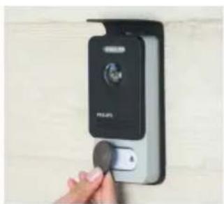
natural_image
Hand inserting a small black object into a wall-mounted device (no visible text or symbols)
Scan me
to find out about our products
Flashez-moi
flowchart
graph TD
    A["120 m max"] --> B["Control Panel"]
    A --> C["Terminal Block"]
    B --> D["230V Unit 1"]
    B --> E["230V Unit 2"]
    B --> F["230V Unit 3"]
    C --> G["230V Unit 4"]
    C --> H["230V Unit 5"]
    C --> I["230V Unit 6"]
    D --> J["Power Supply L"]
    E --> K["Power Supply Z"]
    F --> L["Power Supply Z"]
    G --> M["Power Supply Z"]
    H --> N["Power Supply Z"]
    I --> O["Power Supply Z"]
Fig. 3
flowchart
graph TD
    A["120 m max"] --> B["120 m max"]
    B --> C["Control Panel 1"]
    B --> D["Control Panel 2"]
    B --> E["Control Panel 3"]
    B --> F["Control Panel 4"]
    B --> G["Control Panel 5"]
    B --> H["Control Panel 6"]
    B --> I["Control Panel 7"]
    B --> J["Control Panel 8"]
    B --> K["Control Panel 9"]
    B --> L["Control Panel 10"]
    B --> M["Control Panel 11"]
    B --> N["Control Panel 12"]
    B --> O["Control Panel 13"]
    B --> P["Control Panel 14"]
    B --> Q["Control Panel 15"]
    B --> R["Control Panel 16"]
    B --> S["Control Panel 17"]
    B --> T["Control Panel 18"]
    B --> U["Control Panel 19"]
    B --> V["Control Panel 20"]
    B --> W["Control Panel 21"]
    B --> X["Control Panel 22"]
    B --> Y["Control Panel 23"]
    B --> Z["Control Panel 24"]
    B --> AA["Control Panel 25"]
SOMMAIRE
1 CONSIGNES DE SÉCURITÉ ......p.2
2 CONTENU DU KIT ...... p.2
3 GÉNÉRALITÉ....p.3
4 NOMENCLATURE....p.3
5 INSTALLATION DU PRODUIT......p.5
natural_image
Simple line drawing of a rectangular electronic device with a screen and indicator label (no text or symbols on the device itself)
natural_image
Simple line drawing of a rectangular frame with mounting holes (no text or symbols)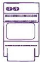
natural_image
Line drawing of a Philips electronic device with a circular button and control panel (no text or symbols on the device itself)


5. 5 badges RFID :
text_image
SNPLID SNPLID DCS 3300 VOP CE5. INSTALLATION DU PRODUIT
natural_image
Line drawing of a hand holding a small object with a pointer, no text or symbols present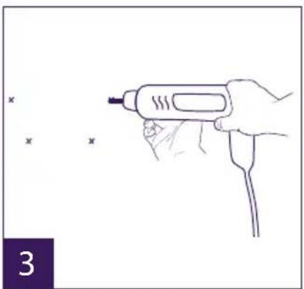
natural_image
Line drawing of a hand holding a handheld tool with a probe, no text or symbols present
natural_image
Hand holding a small object with three small 'x' marks nearby (no text or symbols)
natural_image
Hand holding a tool interacting with a mechanical component, showing curved lines and a bracket (no text or symbols)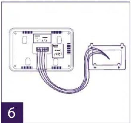
natural_image
Diagram of a device with connected cables showing internal components (no text or symbols)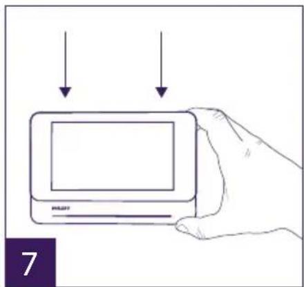
text_image
7natural_image
Line drawing of a hand holding a handheld device with a label 'PULP' and number '1' (no text or symbols on the device itself)
natural_image
Line drawing of a hand holding a handheld electronic device (no text or symbols visible)
text_image
1m60 3
natural_image
Line drawing of hands inserting a card into a device (no text or symbols)
natural_image
Line drawing of a hand holding a handheld electric shaver with a probe inserted (no text or symbols)
natural_image
Line drawing of a hand holding a small object with an 'x' mark above it, no text or symbols present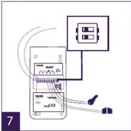
text_image
Diagram showing connections between a device with labeled components and a control panel, likely illustrating a system or system architecture.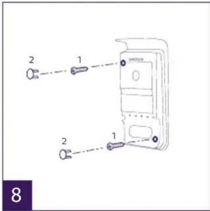
text_image
2 1 2 1 8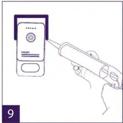
natural_image
Line drawing of a hand using a power soldering iron to press a small electronic device (no text or symbols visible)natural_image
Two purple square icons: one with two overlapping document-like shapes, the other with a speech bubble (no text or symbols)1 2
natural_image
Three purple square icons: a placeholder image, a film strip, and a cross symbol (no text or labels)a
b
C
text_image
Start 21 00 Stop 07 00a
b
C
text_image
TV appear ag04076415-
Wiring
-
Configuring the intercom
- Installing the main or additional monitor
- Installing the main or additional intercom panel
- Installing a camera (optional)
6 MONITOR INTERFACE....p.9
A. Monitoring function and response to a call
B. Intercom function
C. Settings
D. Photo album
E. Video album
7 USER GUIDE.... p.14
8 SMARTPHONE APPLICATION ...... p.15
9 TECHNICAL CHARACTERISTICS....p.21
10 ACCESSORIES....p.23
11 FAQ....p.23
12 TECHNICAL ASSISTANCE - WARRANTY....p.27
13 SAFETY PRECAUTIONS....p.27
14 FCC/CE WARNING...... p.28
15 DECLARATION OF CONFORMITY ...... p.28
1. SAFETY INSTRUCTIONS

Important!
- Please read the user manual carefully before installing or using this product.
- If you are installing this product for a third party, please remember to leave the manual or a copy of it with the end user.
Warning:
• The various components may only be dismantled by an authorised technician.
Safety precautions:
- To ensure the safe operation of the system, installers, users and technicians must follow all the safety procedures described in this manual.
- Specific warnings and warning symbols are marked on the components where necessary.
2. CONTENTS OF THE KIT

natural_image
Simple line drawing of a rectangular electronic device with a screen and a labeled pointer (no text or symbols on the device itself)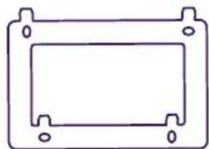
natural_image
Simple line drawing of a rectangular frame with corner holes (no text or symbols)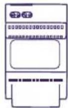
- 7" monitor 2. Wall bracket 3. Modular power
supply
natural_image
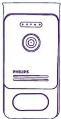
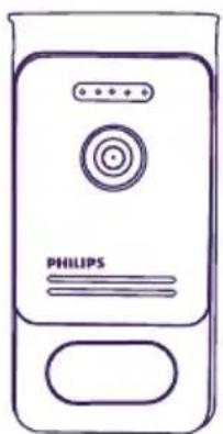
Line drawing of a Philips electronic device with a circular button and control panel (no text or symbols on the device itself)- Intercom panel


5. 5 RFID badges:
2 user badges (grey)
1 admin badge (yellow)
1 - (red)
1 + (blue)
3. GENERAL
This videophone consists of an indoor answering unit with a touch screen and an outdoor panel with an intercom and camera, allowing you to see and communicate with the visitor who has pressed the bell. It is easy to install as only two wires are needed for all functions: bell, video image, intercom and strike plate and automatic opener controls.
The WelcomeEye technology allows you to share the intercom panel between 2 families. Each family can own up to three monitors.
The system can operate up to one camera and two intercom panels per family.
To get the most out of your intercom, please read this instruction manual carefully.
4. NOMENCLATURE
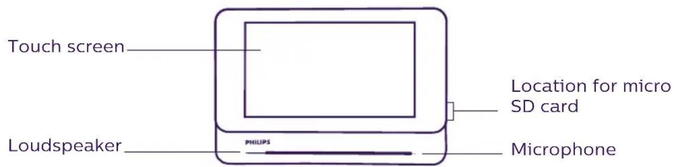
Monitor:
text_image
Touch screen Location for micro SD card Loudspeaker PHILIPS Microphone
text_image
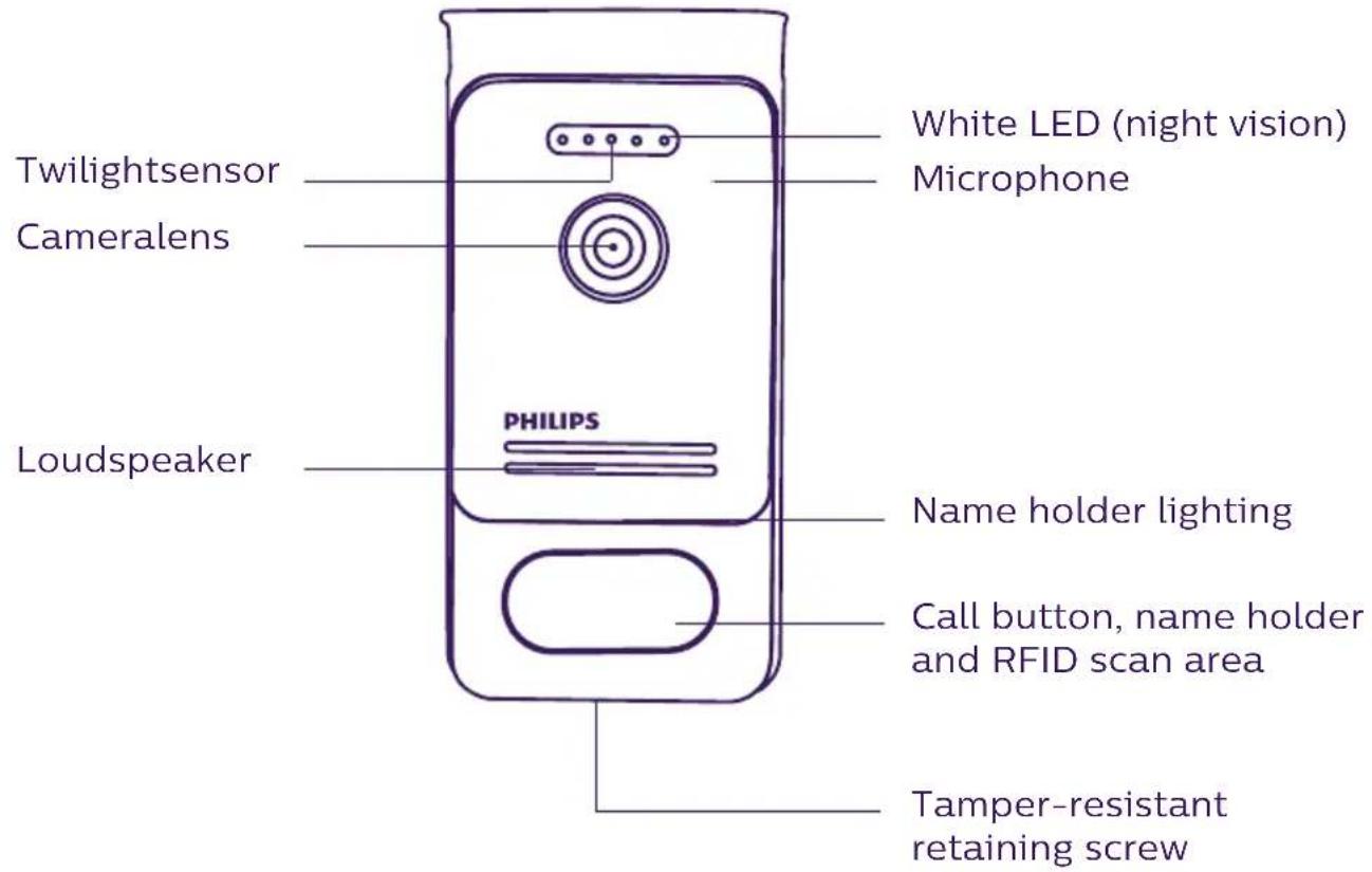
Power supply terminal block Terminal block for connection to the intercom panel and accessoriesIntercom panel:
text_image
Twilightsensor Cameralens Loudspeaker PHILIPS White LED (night vision) Microphone Name holder lighting Call button, name holder and RFID scan area Tamper-resistant retaining screw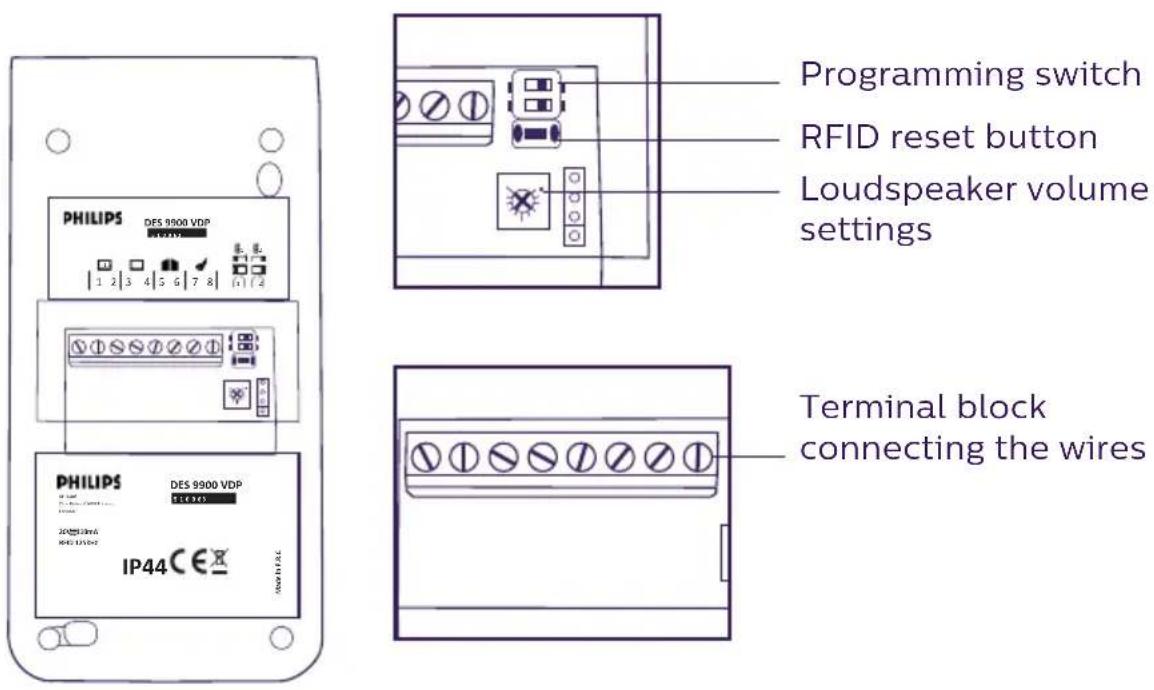
text_image
PHILIPS DES 9900 VDP 1 2 3 4 5 6 7 8 1 2 3 4 5 6 7 8 PHILIPS DES 9900 VDP 1 2 3 4 5 6 7 8 IP44 1 2 3 4 5 6 7 8 1 2 3 4 5 6 7 8 1 2 3 4 5 6 7 8 1 2 3 4 5 6 7 8 1 2 3 4 5 6 7 8 1 2 3 4 5 6 7 8 1 2 3 4 5 6 7 8 1 1 2 3 4 5 6 7 8 1 2 3 4 5 6 7 8 1 2 3 4 5 6 7 8 1 2 3 4 5 6 7 8Notes:
- When someone presses the call button, the inside monitor rings and the video is displayed.
- To change the nameplate label, remove the front cover and unclip the plastic cap behind the label.
5. PRODUCT INSTALLATION
Important notes and advice:
- To make the most of your intercom panel, we recommend configuring it (RFID, for 1 or 2 families, 1 or 2 intercoms, loudspeaker volume) before final installation. To do this, a table connection may be necessary to check that the settings are correct.
- If you test your product before installing it, ensure that you do not test it with the intercom panel and the monitor in the same room to avoid the video doorphone emitting a shrill noise (feedback).
- Do not expose the camera lens to direct sunlight or a reflective surface.
- We recommend running the cables through a protective sheath to protect them against breakage and bad weather.
- For the WelcomeEye Connect version, to make the most of your monitor's Wi-Fi function, we advise you to check that your Wi-Fi network is accessible from where it is installed.
1. Wiring
To avoid the risk of interference and malfunctions, do not run the videophone cable through the same sheath as the electrical cables.
Warning: Do not double up the wires to increase their section.
a. Connecting the videophone (monitor, intercom panel and camera)
Wires to be used: two wires 0.75mm^2 with 80m length or two wires 1.5mm^2 with 120m length.
- Make sure to connect the wires in accordance with one of the wiring diagrams depending on the desired configuration.
- Refer to the label stuck to the back of the monitor and the back of the intercom panel.
- Configure the switches on the back of the intercom panel as well as the monitor interface according to the chosen configuration (see section 2 intercom configuration).
b. Connecting a gate motor
- The intercom provides a dry contact (without power) to be connected to the push button control of the automatic opener.
- Connect it directly to terminals 5 and 6 at the back of the intercom panel (no need to observe polarity).
- The opening function is only possible if the video of the respective intercom panel is displayed.
c. Connecting a strike plate or electric lock
Important: The strike plate or electric lock that you are ordering must have a mechanical memory. The strike plate current cannot exceed 1.1A.
- Connect it directly to terminals 7 and 8 at the back of the intercom panel (no need to observe polarity).
- The opening function is only possible if the video of the respective intercom panel is displayed.
2. Configuring the intercom (see fig. 1, fig. 2 or fig. 3)
a. Configuring the intercom number:
Place switch 2 on the left on intercom no. 1 and on the right on intercom no. 2.
b. Configuring the number of families:
Place switch 1 on the left to be in one-family mode and on the right to be in two-family mode.
c. Intercom volume settings:
Turn the volume control with a Phillips head screwdriver to adjust the intercom volume.
d. Configuring the RFID function:
1) Programming (or resetting) the administrator badges:
When switching on the device for the first time, the badges must be configured in the following order:
-
Press the reset button at the back of the intercom panel for five seconds, the intercom panel will emit six short beeps.
-
Swipe the yellow administrator badge, one short beep confirms the programming.
-
Swipe the blue badge, one short beep confirms the programming.
-
Swipe the red badge, one long beep confirms that the administration badges have been programmed.
2) Add one or more user badges:
-
Swipe the blue badge, four long beeps confirm the activation of the programming mode.
-
Swipe all user badges (grey) to be activated; one short beep confirms the programming of every badge presented.
-
Once all of the badges have been programmed, wait 10 seconds. One long beep confirms the end of the programming process.
3) Remove one or more user badges:
-
Swipe the badge (red); 4 long beeps confirm the activation of the programming mode.
-
Swipe all user badges (grey) to be deactivated; one short beep confirms the deactivation of every badge presented.
-
Once all badges have been deactivated, wait 10 seconds. One long beep confirms the end of the programming process.
4) Remove all user badges:
-
Swipe the administrator badge (blue); 4 short beeps confirm the activation of the administration mode.
-
Swipe 1 user badge (grey) that has already been added; one short beep indicates that all user badges have been deactivated.
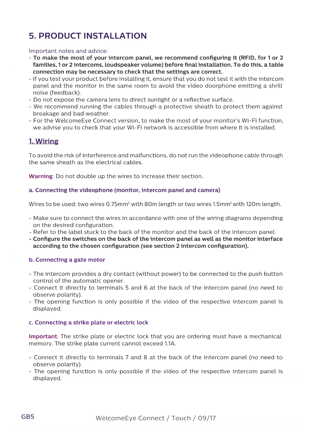
5) Using the badges:
To open the electric strike plate, quickly swipe your pre-programmed grey user badge on the RFID reading field. One short beep confirms the opening of the electric strike plate.
To open the gate motor, hold the badge in front of the RFID scan area for 3 seconds. Two short beeps confirm the opening of the gate.
3. Installing the main or additional monitor
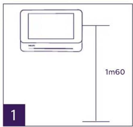
text_image
1m60 1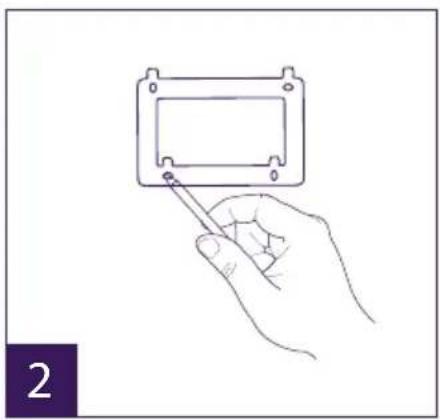
natural_image
Line drawing of a hand holding a small component with a pointer, no text or symbols present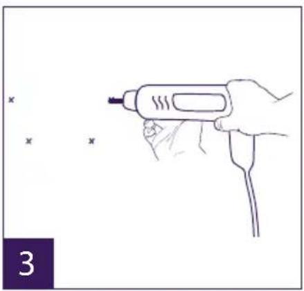
natural_image
Line drawing of a hand holding a handheld tool with a probe, no text or symbols present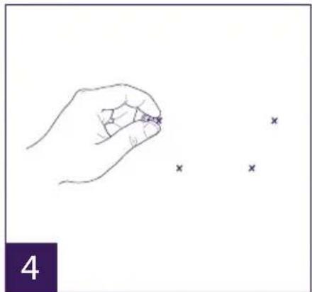
natural_image
Hand holding a pen with three small 'x' marks nearby (no text or symbols)
natural_image
Line drawing of a hand holding a tool next to a rectangular device with curved wires (no text or symbols)
natural_image
Diagram of a device with cable routing from an open panel to a closed terminal block (no text or symbols visible)
text_image
71 - Position the wall bracket so that the screen of the monitor is approximately 1.60m above the ground.
2 - Mark the location of the holes using the U bolt.
3 - Drill.
4 - Use pegs adapted to the bracket (those supplied are suitable for solid walls).
5 - Attach the wall bracket.
6 - Connect the two intercom panel wires and the two power supply wires in accordance with the wiring diagram.
7 - Position the monitor on the wall bracket.
8 - Depending on the configuration selected, and when wiring is completed, the interface may have to be configured.

Warning: during this step, do not connect the power supply to the 230V AC.
4. Installing the main or additional intercom panel
Warning: The product must not be connected to the power supply before wiring is complete.

natural_image
Line drawing of a hand holding a handheld device with a screwdriver inserted (no text or symbols visible)
natural_image
Line drawing of a hand holding a handheld electronic device (no text or symbols visible)
text_image
1m60 3
natural_image
Line drawing of hands installing or adjusting a device component (no text or symbols visible)
natural_image
Line drawing of a hand holding a handheld electric drill pen (no text or symbols)
natural_image
Line drawing of a hand holding a pen with an 'x' mark above it, no text or symbols present
text_image
Diagram showing electrical connections between a device with labeled components and wiring, including a switch and battery.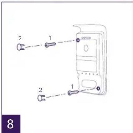
text_image
2 1 2 1 8
natural_image
Line drawing of a hand using a soldering iron to apply a power button to a device (no text or symbols visible)1 - Remove the tamper-resistant screw from the intercom panel.
2 - Tip the intercom panel cover forward.
3 - The intercom's lens should be approximately 1.60m above the ground.
4 - Mark the locations.
5 - Drill.
6 - Use pegs adapted to the nature of the support (the screws supplied are suitable for solid walls).
7 - Connect the two wires from the monitor and, if necessary, connect the electric strike plate and the gate (see section 1. Wiring). Confi gure the switches at the back of the intercom panel (see section 2. Confi guring the intercom).
8 - Insert the screws and refi t the two caps concealing the retaining screws.
Note: screw through the black covers on the back of the intercom panel – do not remove them.
9 - Refi t the front cover of the intercom and tighten the tamper-resistant retaining screw.
10 - Connect the 230V AC power supply to the modular adaptor, for an installation compliant with applicable standards (NFC 15-100 in France).
- Verify the smooth functioning (video call, RFID, etc.).
- When there is a second intercom panel, don't forget to configure the monitor(s)
11 - Attach a silicone seal* between the shield and the wall to stop flowing water.
*Do not use acetic acid-based silicone (vinegar odour).

5. Installing a camera (optional)
Connect the wires in accordance with the wiring diagram.
Choose a suitable place to install the camera.
Ensure that nothing gets in the way of the installation.
Screw the wall section with the screws provided (for solid walls).
Point the camera in the desired direction and tighten the retainer screw.
Configure the monitor(s) ^+ On
6. MONITOR INTERFACE
Main Menu
Lightly touch the screen to turn it on and access the main menu
text_image
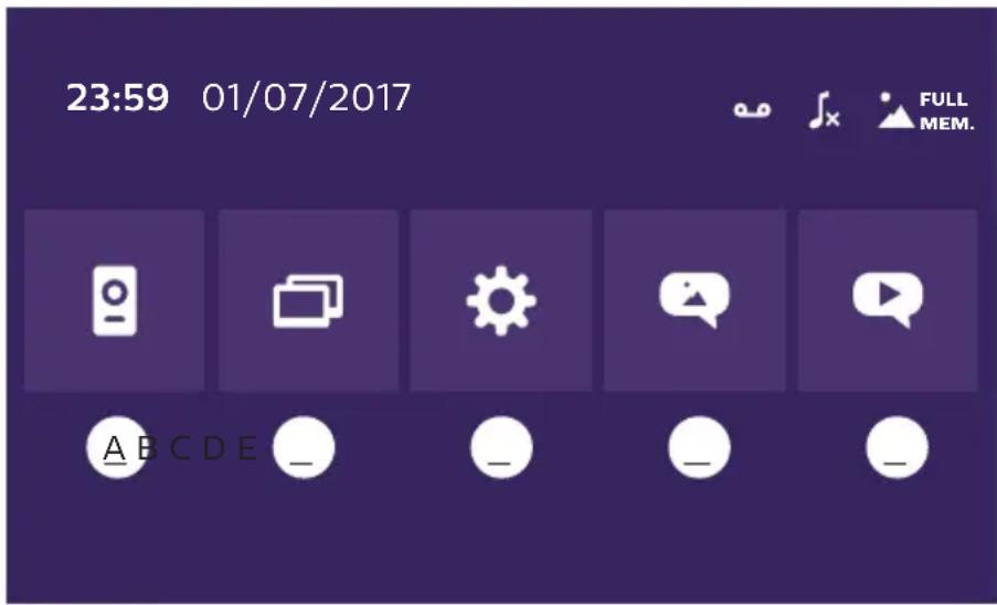
23:59 01/07/2017 FULL MEM. A B C D E _ _ _ _ _A. Monitoring function and response to a call
B. Intercom function
C. Settings
D. Photo album
E. Video album

: indicates that silent mode is active

: indicates that the monitor ringtone is deactivated

: indicates that the memory is full. The oldest photos/videos are replaced with the new recordings.
A. Monitoring function and response to a call

text_image
1 2 3 4 51: To switch to the view of the second intercom panel or camera, or return to the main menu.
2: To establish voice communication with the intercom panel and hang up.
3: To open the electric strike plate.
4: To open the gate.
5: To take a photo or video in accordance with the settings selected.
B. Intercom function


natural_image
Two purple square icons: one with two white document-like shapes, the other with a speech bubble (no text or symbols)1 2
Function only valid if an additional monitor is connected and the parameters are set correctly.
1: To exit the function
2: To call the family's other monitors, to respond when receiving a call from another monitor or to hang up.
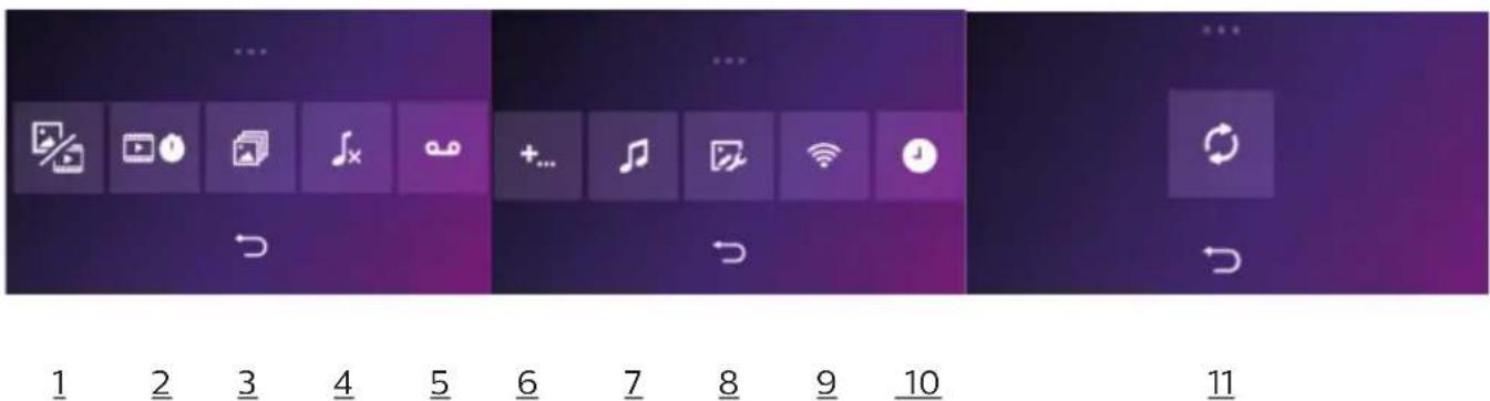
C. Settings

The settings menu consists of three pages for the WelcomeEye Connect and two pages for the WelcomeEye Touch. To switch from one page to the next, simply slide the screen to the right or left.
Click on to return to the previous menu.
text_image
1 2 3 4 5 6 7 8 9 10 11- Visit memory function

natural_image
Three colored square buttons with white icons: a photo, a film strip, and an 'X' symbol (no text or labels)a
b
C
a: Photo record of a visitor.
b: Video recording of a visitor (there must be a formatted micro SD card in the monitor).
c: Deactivation of the visit memory function.
- Video recording configuration (valid if video mode has been selected)
Choose the video recording time (10, 20 or 30 sec) during a missed call or in monitoring mode (note: function inactive without a micro SD card).
- Photo configuration (valid if photo mode has been selected)
Choose the number of photos taken (1, 2 or 3) during a missed call or in monitoring mode.
- De-activation of silent mode
This function turns off the monitor ringtone for a certain period (snooze, etc.). The monitor LEDs will continue flashing to indicate a call.

text_image
Start 21 00 Stop 07 00a
b
C
a: activate (On) / deactivate (Off) the monitor's silent mode.
b: Time when the ringtone will be deactivated.
c: Time when the ringtone will be reactivated.
- Answering system function (only on WelcomeEye Connect, valid if video mode has been selected)
This function allows you to record a voice message which will be played if the call is not answered. Video recording must be configured during calls to activate this function.

text_image
Ona
b
C
a: To activate or deactivate voice message function.
b: To play back the recorded voice message.
c: To start and stop voice message recording (maximum duration of the message: 15s.).
6: Configuration of the WelcomeEye system's options

text_image
+ + On + Off + Off Offa
b
C
d
a: Activation of a second intercom panel (choose On if a second intercom panel is used).
b: Activation of the camera option (choose On if a camera is used).
c: Configuration of the monitor(s). When the system has several monitors, you must configure one Master monitor and Slave monitors. If the system only features one monitor, choose Off.
d: Activation of the videophone's energy saving mode. When the energy saving mode is activated (On), the product's consumption is reduced. The intercom panel is placed on standby, therefore the monitor no longer receives calls.
7: Audio settings

text_image
3 2 1 6 1a
b
C
d
e
a: Choice of ringtone during a call from intercom panel 1
b: Choice of ringtone during a call from intercom panel 2 (only if an additional intercom panel has been configured)
c: Choice of ringtone during an intercom call (only if an additional monitor has been configured)
d: Volume settings for the monitor ringtone
e: Volume settings for the monitor loudspeaker during communication.
8: Image settings
Image brightness, contrast and colour settings.
9: Wi-Fi network management (only on WelcomeEye Connect)

text_image
On 10 s ia
b
C
a: Activation (On) or deactivation (Off) of the Wi-Fi network.
b: Conf i guration of the time between the visitor ringing the bell and when the notifi cation is sent to the smartphone.
c: Access to information on the network and Wi-Fi network reset.
Note: The use of the Wi-Fi network and the smartphone application is detailed in chapter 8 application.
10: Time and date settings
a: time and date settings

bar
| Year | Value | |---|---| | 2017 | 23 | | 2018 | 59 | | 2019 | 01 | | 2020 | 31 | | 2021 | 2017 |b: date (applies to the main menu only) and time format settings.
Slide the image to access this menu.

text_image
YYYY/MM/DD 24 H11: Reset menu
a: Micro SD card resetting and formatting. May be necessary when using an micro SD card for the first time.
b: Internal memory reset.
c: Factory reset of the product and return to default values (visit memory function, configuration of video and photo recordings, ringtone deactivation, answering system function, options configuration, audio settings, image settings, Wi-Fi, time and date). The photos and videos recorded are saved.
D. Photo album

To access the album of recorded photos. The figure in the red circle indicates the number of unread photos.

text_image
23:59 01/07/2017 23:59 01/07/2017 23:59 01/07/2017 23:59 01/07/2017 23:59 01/07/201723:59 01/07/2017
: time and date photo was taken. Click on it to view the photo.

: To delete one or several photos. Click on the waste bin then select the photos to be deleted and click on the waste bin again to delete them.
E. Video album

Menu only accessible if a micro SD card is inserted.
To access recorded videos. The figure in the red circle indicates the number of unplayed videos.
The viewing and deletion procedure is identical to the photo album.
7. USER MANUAL
Response to a call:
- Pressing the intercom panel button triggers an audible signal and the monitor turns on. You have up to 20 seconds to respond to the call. Once the visitor has been identified, press the 🔔 key to begin talking.
- After two minutes of conversation, communication stops and the screen returns to the home page. If the conversation ends before two minutes, press the key to stop communication. The screen returns to the home page.
- To refresh the picture, press on the home screen. To refresh for an additional 120 seconds of conversation, press the key
- Control an electric lock or strike plate by pressing the key
- Control an automatic gate opening mechanism by pressing the key
Missed call:
- Pressing the intercom panel button triggers an audible signal and the monitor turns on. If the visit memory function is activated (photo or video), a screenshot of the visitor is automatically sent to the user.
- If you choose to take photos, the number of images are captured corresponds with the number of photos you have selected (1, 3 or 5). These photos are stored in the internal memory if no micro SD card is inserted. Otherwise they are stored on the micro SD card.
Note: the photos saved in the internal memory may not be copied onto a memory card.
- You can also choose the video recording. In this case a video with sound is recorded. This function requires a micro SD card. Videos will only be recorded on your micro SD card. The recording time can be adjusted (10, 20 or 30 seconds).
- When there is a recorded message (visitor screenshot or message), a red circle with a figure indicates the number of unread messages on the home screen.
- For the WelcomeEye Connect version, an answering system function is available. If the answering system function is activated, the recorded message of the answering system is played on the intercom panel. At the end of the message, the system automatically switches to video and audio recording mode. The visitor can therefore leave a message. Note: the answering system function is only possible if the video recording is activated.
Standby
- The screen is automatically placed on standby which means the screen enters sleep mode for energy saving and screen sustainability purposes.
- If the monitor is in a menu other than the main menu, it automatically switches to the main screen after 15 seconds of inactivity.
- If the monitor is in the main menu, it automatically switches to standby mode after 15 seconds of inactivity.
- Lightly touch the screen to exit the standby mode.
8. SMARTPHONE APPLICATION
Connect a monitor to the Wi-Fi network
-
Download the Philips WelcomeEye application onto your smartphone. From the Apple store or Play store
-
From the monitor, go to then and activate Wi-Fi:
-
Go to , and the following menu appears:


text_image
UID XXXXXXXXXXXXXXXXX ( )
Note: If the icon does not appear on the second line, reset Wi-Fi by clicking on then wait until the icon appears (approximately 30s.).

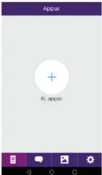
text_image
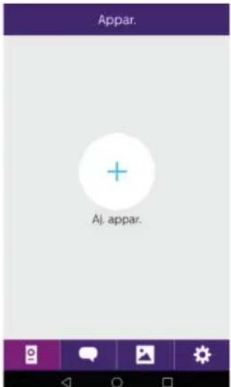
Appar. Aj. appar.- From the WelcomeEye application, click on + to add a device.
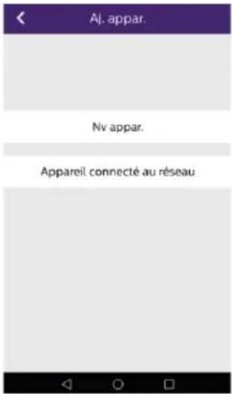
- Android : Click on new device and then next

text_image
Nv appar. cg03c1a70e- The UID of your monitor should appear. Click on it.
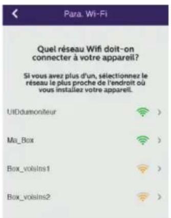
Choose the box to which you wish to connect your monitor, enter its password and click on next.

5 Bis. IOS : Click on new device and then next.
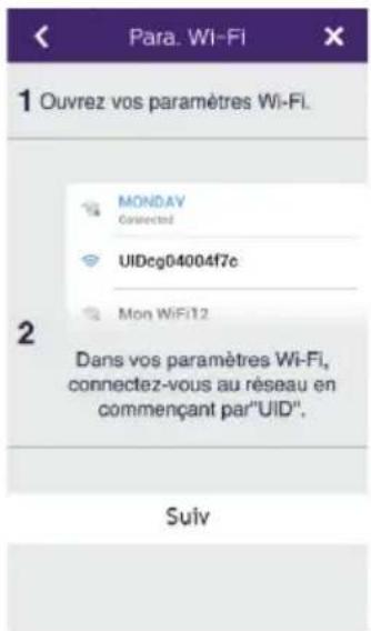
Exit the application and go to the Wi-Fi settings of the smartphone. Log in to the Wi-Fi starting with 'UIDcg.....'.
text_image
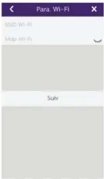
Para. Wi-Fi SSID Wi-Fi Map Wi-Fi SulvReturn to the application and click on next. Enter the name of your network and its password, then click on next. : Show password
text_image
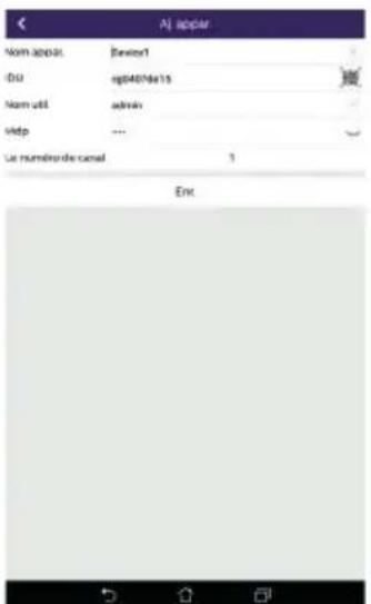
Aj - RODAY Nom appue: Device1 IDU cp4407e16 Nom USB admin Map --- Le numéro de canal 5 Enc:- Enter the name you wish to give your device, the user name, password and number of doors (= channel number) you wish to control. You will be asked for the password every time you wish to open your electric strike plate or gate from the application.
Warning: default password 1234.
Channel No
1 = single strike control
2 = gate and gate control
Click on Save.
Your videophone is now connected to the Wi-Fi network and your smartphone can receive calls.
Add a smartphone to a connected videophone
- Download the Philips WelcomeEye application onto your smartphone from the Apple App Store or Google Play Store

Warning: deactivate the smart Wi-Fi network mode on the smartphone if it is activated.
text_image
Appar. Aj. appar.- From the WelcomeEye application, click on + to add a device.

- Click on device connected to the network, then conn. dev. Make sure the smartphone is connected to the same Wi-Fi network as the monitor.

text_image
My apper. g0407685- The UID of your monitor should appear. Click on it.
text_image
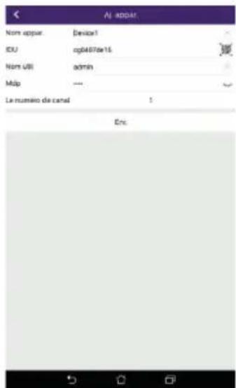
Al appear Nom appos: Devest DU: np40/16a15 Nom util: admin Velp: ... Le numéro de canal 1 Enc- Enter the name you wish to give your device, the user name, password and number of doors (= channel number) you wish to control. You will be asked for the password every time you wish to open your electric strike plate or gate from the application.
Warning: If you choose 1 for the channel number, you may only control the electric strike plate.
Click on Save.
- Your smartphone can now receive calls from your videophone.
Interface function

text_image
Appar(!) Device1Contains the different devices and enables switching to monitoring mode.
+ Adding a device
Click on the picture to enter monitoring mode.
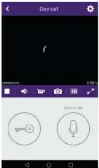
text_image
Device1 ANNEXION... OKB/s Push to Talk
Managing camera settings: name, password, Wi-Fi network, Number of channels and alarm.

Start/stop my real-time viewing.

Switch the sound on/off.

Record a video.

Take a photo.

Reduces the quality of the video (1 bar) or only records the sound (0 bar) if bandwidth is limited. For optimum performance, minimum throughput must be 40 kB/s.

Full screen mode

Open the electric strike plate or gate (default password: 1234).
Note: the number of doors must be set to 2 to control the opening of the gate

Press and hold to talk to the visitor.

text_image
Activité
To delete the recordings

Contains the recordings.
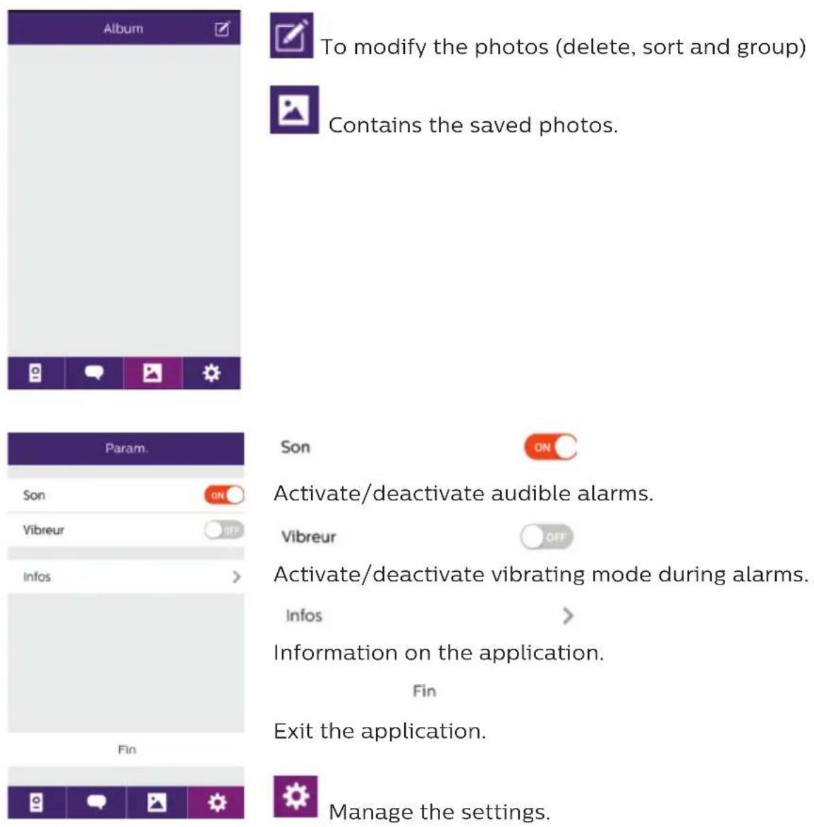
To modify the photos (delete, sort and group)
Contains the saved photos.
Son
Activate/deactivate audible alarms.
Vibreur
Activate/deactivate vibrating mode during alarms.
Infos
Information on the application.
Fin
Exit the application.
Manage the settings.
9. TECHNICAL CHARACTERISTICS
Monitor:
ref.: 538102 (WelcomeEye Connect)
ref.: 538101 (WelcomeEye Touch)
- 2 wires
- 7" touch screen
- Resolution 800 x 480
- Class 10 micro SD card up to 32GB (not supplied)
- Wi-Fi 2.4 GHz IEEE 8111 b/g/n (WelcomeEye Connect only)
- Radio power emitted: 18 dB maximum
- Current consumption: 550mA (Connect), 470mA (Touch)
- Power consumption: 13.2W (Connect), 11.3W (Touch)
- 6 ringtones (85dB)
- Dimensions: 142(h) x 210(l) x 15(d) mm
Intercom panel: (WelcomeEye Outdoor)
ref.: 531006
- C-MOS colour sensor 900TVL
- Viewing angle H130°, V90°
- Night vision (white LEDs)
- Strike plate control 12V/1.1A/ 1,5 s.
- Gate control: breaking capacity 12V/2A
- RFID (125kHz)
- IP44
- Operating temperature: -20°C / +50°C
- Dimensions: 168(h) x 82(l) x 38(d) mm
WelcomeEye application (for WelcomeEye Connect only):
- Android v4.4 or above
- iOS 7 or above
- PUSH notification
WelcomeEye AddComfort: (additional monitor) ref.: 531003
- 2 wires
- 7" screen
- Resolution 800 x 480
- Current consumption: 460mA
- Power consumption: 11.1W
- 6 ringtones (85dB)
- Dimensions: 142(h) x 210(l) x 15(d) mm
WelcomeEye AddCompact: (additional monitor) ref.: 531005
- 2 wires
- 4.3" screen
- Resolution 480 x 272
- Current consumption: 400mA
- Power consumption: 9.6W
- 6 ringtones (85dB)
- Dimensions: 116(h) x 146(w) x 16(d) mm
WelcomeEye Outdoor: (Additional intercom panel) ref.: 531006
- C-MOS colour sensor 900TVL
- Viewing angle H130°, V 90°
- Night vision (white LEDs)
- Strike plate control 12V/1.1A/ 1,5 s.
- Gate control: breaking capacity 12V/2A
- RFID (125kHz)
- IP44
- Operating temperature: -20°C / +50°C
- Dimensions: 168(h) x 82(w) x 38(d)
WelcomeEye Cam: (additional camera) ref.: 531007
- C-MOS colour sensor 900TVL
- Viewing angle: H95°, V75°
- Operating temperature: -20°C / +50°C
- Protection index: IP66
10. ACCESSORIES
WelcomeEye AddCompact - DES 9300 DDE (ref.: 531005)*
WelcomeEye AddComfort - DES 9500 DDE (ref.: 531003)*
WelcomeEye Cam - DES 9900 CVC (ref.: 531007)
WelcomeEye Outdoor - DES 9900 VOS (ref.: 531006)**
WelcomeEye Lock - DES 1000 EDL (ref.: 531008)
WelcomeEye Lock - DES 1100 EDL (ref.: 531009)
WelcomeEye Power - DES 1000 DPS (ref.: 531010)**
WelcomeEye TAG - DES 1000 ACI (ref.: 531011)**
* Refer to the complete WelcomeEye Comfort/Compact instructions available on the www.philips.com website for more information.
** Refer to the complete WelcomeEye Connect/Touch instructions available on the www.philips.com website for more information.
11. FAQ
| Failure Cause Solution | ||
| ·The monitor does not turn on | ·The monitor is not connected to a power source | ·Verify that the power supply is properly connected and turned on·Check the polarity on the monitor or at the power supply output |
| ·Poor connection or short circuit on the line | ·Resolve the connection problem | |
| ·Does not work when installed for the first time | ·Connection error ·The device is equipped with major protections. Disconnect the power supply for at least 1mn, correct the installation error and reconnect. It should be noted that the protections will not be of any help if the product is directly connected to 230VAC, and that this error is not covered by warranty. | |
| ·Reversed polarity of the supply voltage | ||
| ·Short-circuit on the line | ||
| ·The intercom panel is on but the monitor does not ring | ·Switch configuration of the intercom panel | ·Verify that the intercom panel is not programmed in dual-family mode.Reminder: single-family = switch 2 set to ON, dual-family = switch 2 set to OFF. Don't forget to turn the power off for 5 seconds to activate the new settings (page 6) |
| ·Configuration menu of the monitor | ·Verify that the monitor is valid | |
| ·Connection · Verify that the monitor is connected to 1 and 2 of the intercom panel (for single-family use) | ||
| ·Energy saving mode activated | ·(page 12) | |
| ·Poor picture and/or sound | ·Environment · Check that the wires used are the correct size and that the videophone's connection wires are not in the same sheath as the 230VAC wires | |
| ·Purple picture · Connection · The connection cable must not be tangled | ||
| ·Image is too bright · Camera position · Do not expose the lens of the camera directly to sunlight or to a reflective surface. | ||
| ·The volume of the intercom panel is too low | ·Settings · Re-enter the settings on the back of the intercom panel | |
| ·The volume from the intercom panel is too low | ·The microphone hole of the intercom panel is blocked | ·Verify and rectify |
| ·The Dual-family mode is not working | ·Configuration · Verify | that the intercom panel is not programmed in dual-family mode.Reminder: single-family =switch 2 set to ON, dual-family =switch 2 set to OFF. Don't forget to turn the power off for five seconds to activate the new settings (page 6) |
| ·Configuration menu of the monitors | ·Verify that the monitors are valid (BOTH of them) | |
| ·Connection · The mon | itors of family 1 must be connected to 1 and 2 of the intercom panel, those of family 2 to 3 and 4 | |
| ·The additional monitor is not working | ·Configuration · Verify | that you have correctly configured the menus of your monitors with 1 SINGLE master terminal, the others MUST be configured as slaves |
| ·Connection · Verify | that the additional monitor is connected to 1 and 2 of the intercom panel for single-family operation | |
| ·The additional intercom panel is not working | ·Configuration · Verify | the position of switch 1 on the panels (page 6); it must be different. Don't forget to turn the power off for five seconds to activate the new settings |
| ·Configuration menu of the monitors | ·Verify that the monitors are valid (BOTH of them) | |
| ·The micro SD card is not recognised "Message SD card error" | ·Folders not created | When inserted for the first time, it must be formatted by the monitor (page 13) |
| ·Quality of the micro SD card | ·Use at least one class 10 card | |
| ·After inserting the micro SD card, cannot access the photos on the internal memory·Cannot retrieve the photos from the internal memory on the micro SD card | ·The micro SD card has priority, and the internal memory can no longer be accessed | ·Remove the micro SD card to access the internal memory |
| ·Normal operation | ||
- No video recording · Absence of micro SD card
- Videos can only be recorded when there is a micro SD card in the monitor
- Card format unsuitable
- Type of micro SD card or SDHC mic, no SDXC mic
- Unsuitable card size
- 64MB min, 32GB max class 10
- Check recording mode (page 11)
- The strike plate and gate motor are controlled via the monitor, not the RFID
- Programming error • Reset and resume the badge programming procedure.
Reminder: short swipe of the badge = electrical control, long swipe = dry contact control
- Poor image and/or sound from the smartphone*
- Stream problem • The stream must be at least 40Kb/s
- Modify the stream from the app settings (change the no. of frames/second)
- The opening of the electric strike plate is controlled by the application, but the opening of the gate is not*
- Configuration • In application settings, verify that "code verr" = 2
Reminder: the command can only be sent if a conversation via the intercom is ongoing
• The strike plate is not controlled via the monitor
- The strike plate or electric lock that you are ordering must have a mechanical memory. The strike plate current cannot exceed 1.1A.
- Connect it directly to terminals 7 and 8 at the back of the intercom panel (no need to observe polarity).
- The opening function is only possible if the video of the respective intercom panel is displayed.
* WelcomeEye Connect only
Reminder: Videos can only be recorded when there is an micro SD card in the monitor.
The photos and videos launched by the application are recorded on the smartphone.
The application only allows access to intercom panel views, not the additional cameras.
Notes: To check whether or not the product is faulty, we recommend connecting it over a short distance (3m of wiring). If the symptoms persist, the product is faulty. If not, check the installation and cable used.
12. TECHNICAL ASSISTANCE - WARRANTY
This product is guaranteed for parts and labour in our workshops.
The warranty does not cover: consumables (batteries, etc.) and damage caused by misuse, improper use, improper installation, external intervention, damage due to physical or electrical shocks, dropping, or atmospheric phenomena.
- Do not open the device, as this will void the warranty.
- If the unit is returned for After Sales Service, protect the unit to prevent scratches.
- Clean with a soft cloth only, no solvents. The guarantee is void if parts have been dismantled. Before cleaning it, disconnect the equipment or switch it off at the mains.
Warning: Do not use any gasoline or carboxylic acid, alcohol or similar treatment. In addition to damaging your device, the fumes are also hazardous to your health and are explosive.
Do not use any tool that can conduct voltage (wire brush or other sharp tool, etc.) for cleaning.
The till receipt or invoice is your proof of purchase date.
If necessary, the contacts and opening hours of our technical assistance centres are available on the www.philips.com website.

text_image
WARRANTY CARD Mr / Mrs : _ Phone number : _ Address : _ E-mail : _ Date of purchase : _/ _/ (DD/MM/YYYY) Dealer : _ Dealer Phone : _ Dealer address : _ Serial number PHI/1031/ Important: Please keep this warranty card with your proof of purchase.Philips and Philips' shield emblem are registered trademarks of Koninklijke Philips N.V. and are used under licence. This product has been manufactured by and is sold under the responsibility of CFI Extel SAS, and CFI Extel SAS is the sole guarantor of this product.
13. SAFETY PRECAUTIONS
Any damage caused by a failure to adhere to the manual shall void the warranty. We assume no liability for damages resulting therefrom!
We cannot be held responsible for any damage to property or persons caused by incorrect use or a failure to adhere to the safety instructions.
This product has been manufactured in full compliance with safety instructions. In order to
maintain this status and get the most out of the product, users must adhere to the safety instructions and warnings contained in this manual.
4: This symbol indicates that there is a risk of electric shock or short-circuit.
- You should only use this product with a voltage between: 100-240 Volts and 50-60 hertz. Never attempt to use this device with a different voltage.
- Ensure that all the system's electrical connections conform to the instructions for use.
- In commercial establishments, ensure that you adhere to the electrical installation accident prevention regulations.
- In schools, training facilities, workshops, etc. qualified personnel must be on hand to monitor electronic equipment operation.
- You must follow the instructions for use of any other devices connected to the system.
- Please contact an experienced person if you have any doubts regarding equipment operation or safety.
- Never plug in or unplug electrical equipment with wet hands.
- When installing this product, check that the power supply cables are not at risk of being damaged.
- Never replace damaged electrical cables yourself! In this case, remove them and call an expert.
- The mains supply should be located close to the device and must be easily accessible.
- An easily accessible cut-off system (switch disconnector, circuit breaker, equivalent system) must be integrated into the building's wiring installation for the equipment connected to the power grid.
- Keep a minimum distance around the device to guarantee sufficient ventilation.
- Ventilation should not be blocked by covering the ventilation opening with an object such as a newspaper, tablecloth or curtain, etc.).
- No open flame source such as a burning candle must be placed on the device.
- Respect the product's operating temperature.
- The device must not be exposed to liquid flow or splashing. Do not place any objects filled with liquid such as vases on the device.
14. FCC/CE WARNING
Note: This equipment has been tested and found to comply with the limits for the Class B, in compliance with current European safety standards. These limits are designed to provide reasonable protection against interference in a residential installation. This equipment uses and emits a radio frequency energy and may cause interference with radio communications if not installed and used according to the instructions.
However, there is no guarantee that there will be zero interference in any given installation. If this equipment causes interference with radio or TV reception, which can be determined by starting and stopping the equipment, we recommend resolving this interference by using at least one of the following measures:
- Reorient or move the receiving antenna
- Increase the distance between the equipment and the receiver
- Use a plug on a different circuit to that being used by the receiver
15. DECLARATION OF CONFORMITY
The undersigned, CFI-Extel, declares that the WelcomeEye radioelectric equipment complies with the 2014/53/EU directive. The full text of the EU declaration of conformity is available at the following address: www.cfi-extel.com.
INHALT
1 SICHERHEITSANWEISUNGEN....S. 2
2 INHALT DES SETS S. 2
3 ALLGEMEINES....S. 3
4 NOMENKLATUR....S.3
5 INSTALLATION DES PRODUKTS....S. 5
natural_image
Simple line drawing of a rectangular electronic device with a screen and indicator block labeled 'PHILIPS' (no text or symbols on the device itself)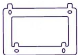
natural_image
Simple line drawing of a rectangular frame with mounting holes (no text or symbols)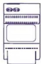
natural_image
Line drawing of a Philips electronic device with a circular button and control panel (no text or symbols on the device itself)- Türsprechanlage

natural_image
Five simple oval shapes with small inner segments, arranged horizontally (no text or symbols)5.5 RFID-Tags:
2 Benutzer (grau)
1 Administrator (gelb)
1 - (rot)
1 + (blau)
3. ALLGEMEINES
natural_image
Line drawing of a hand holding a handheld electric tool with a probe, no text or symbols present
natural_image
Hand holding a small object with three small 'x' marks nearby (no text or symbols)
natural_image
Diagram of a hand holding a tool interacting with a mechanical component, showing curved lines and a bracket (no text or symbols)
natural_image
Diagram of a device with cable routing from an internal component (no text or symbols visible)
text_image
7natural_image
Line drawing of a hand holding a handheld device with a label 'PHILIPS' and a number 1, no text or symbols on the device itself.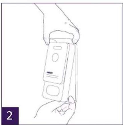
natural_image
Line drawing of a hand holding a handheld electronic device (no text or symbols visible)
text_image
1m60 3
natural_image
Line drawing of hands inserting a card into a device (no text or symbols visible)
natural_image
Line drawing of a hand holding a handheld electric drill pen (no text or symbols)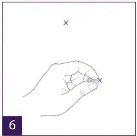
natural_image
Line drawing of a hand holding a small object with two 'x' marks above it, no text or symbols present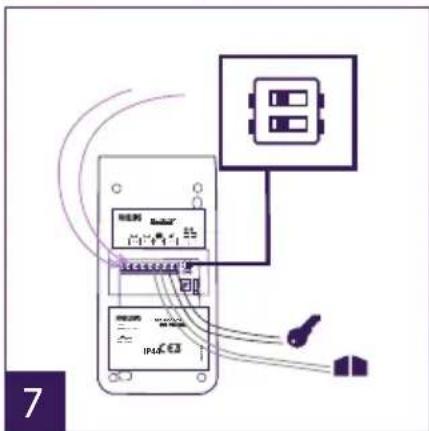
text_image
Diagram showing connections between an electrical device and a control panel with labeled components and wiring paths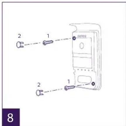
text_image
2 1 2 1 8
natural_image
Line drawing of a hand using a power tool to press a device into a control panel (no text or symbols visible)natural_image
Two overlapping document icons on purple background: one with two white rectangles, the other with a white speech bubble (no text or symbols)1 2
text_image
Start Stop a b ca: Klingelton des Monitors aktivieren (On)/deaktivieren (Off).
natural_image
Line drawing of a rectangular electronic device with a screen and indicator line (no text or symbols on the device itself)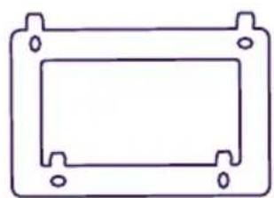
natural_image
Simple line drawing of a rectangular frame with mounting holes (no text or symbols)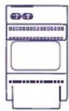
- Scherm 7" 2. Wandhouder 3. Modulaire
voeding
natural_image
Line drawing of a Philips electronic device with a circular button and control panel (no text or symbols on the device itself)- Straatunit


5. 5 RFID-badges
5. INSTALLATIE VAN HET PRODUCT
natural_image
Line drawing of a hand holding a small object with a screwdriver, no text or symbols present
natural_image
Line drawing of a hand holding a handheld tool with a probe, no text or symbols present
natural_image
Hand holding a small object with three small 'x' marks nearby (no text or symbols)
natural_image
Line drawing of a hand holding a tool next to a rectangular device with curved wires (no text or symbols)
natural_image
Diagram of a device with cable routing from an internal component (no text or symbols visible)
natural_image
Hand holding a tablet device with two downward arrows above it, no text or symbols presentnatural_image
Line drawing of a hand holding a handheld device with a label 'GREEN PAPER' and a finger pointing to it (no text or symbols on the device itself)
natural_image
Line drawing of a hand holding a handheld electronic device (no text or symbols visible)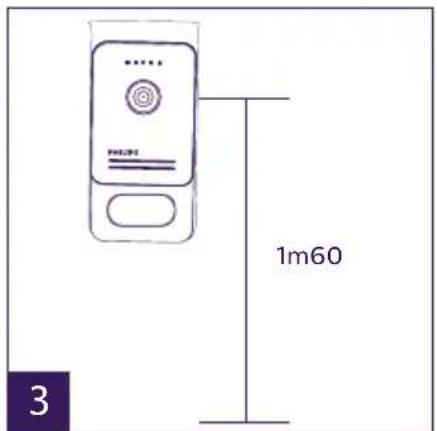
text_image
1m60 3
natural_image
Line drawing of hands inserting a card into a mobile device (no text or symbols)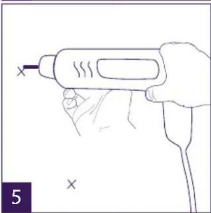
natural_image
Line drawing of a hand holding a handheld electric drill pen (no text or symbols)
natural_image
Line drawing of a hand holding a small object with two 'x' marks above it, no text or symbols present
text_image
Diagram showing connections between a device with labeled components and wiring, including a switch and power supply unit.
text_image
2 1 2 1 8
natural_image
Line drawing of a hand using a power tool to<|rotate_right|> a device (no text or symbols visible)natural_image
Two purple square icons: one with two white document-like shapes, the other with a speech bubble (no text or symbols)1 2
text_image
Screenshot of a mobile app status bar with icons for music, video, audio, and others, showing numbered UI elements below.bar
| Stage | Start | Stop | |---|---|---| | Start | 21 | 07 | | Stop | 00 | 00 | a b ctext_image
UID xxxxxxxxxxxxxxxxxxxx (1) W ←ref: 538102 (WelcomeEye Connect)
ref: 538101 (WelcomeEye Touch)
14. FCC/EG-WAARSCHUWING
natural_image
Line drawing of a Philips monitor with no text or symbols on the screen or body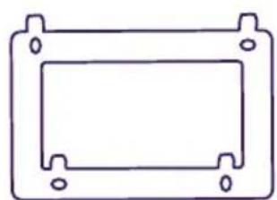
natural_image
Simple line drawing of a rectangular frame with mounting holes (no text or symbols)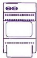
natural_image
Line drawing of a Philips electronic device with a circular button and control panel (no text or symbols on the device itself)
natural_image
Five simple oval shapes with small inner circles, arranged horizontally (no text or symbols)5. 5 breloków RFID:
text_image
HUNT 1m60 1
natural_image
Line drawing of a hand holding a small object with a screwdriver, no text or symbols present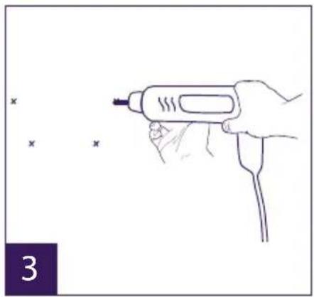
natural_image
Line drawing of a hand holding a handheld electric tool with a probe, no text or symbols present
natural_image
Hand holding a small object with three small 'x' marks nearby (no text or symbols)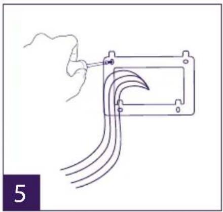
natural_image
Line drawing of a hand holding a tool next to a rectangular device with curved wires (no text or symbols)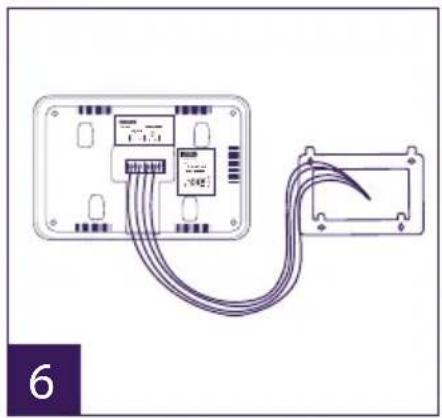
natural_image
Diagram of a device with cable routing from an internal component (no text or symbols visible)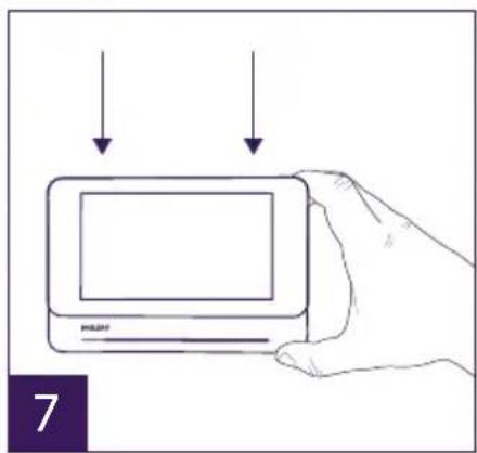
text_image
7natural_image
Line drawing of a hand holding a handheld device with a screwdriver inserted (no text or symbols)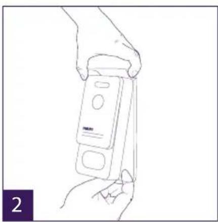
natural_image
Line drawing of a hand holding a device with a label 'PANAN' on its side (no text or symbols on the device itself)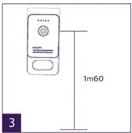
text_image
1m60 3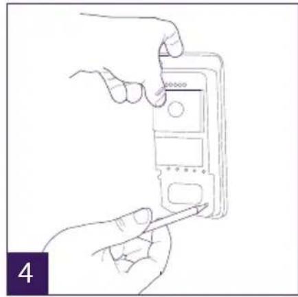
natural_image
Line drawing of hands inserting a card into a device (no text or symbols)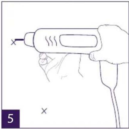
natural_image
Line drawing of a hand holding a handheld electric shaver with a probe inserted (no text or symbols)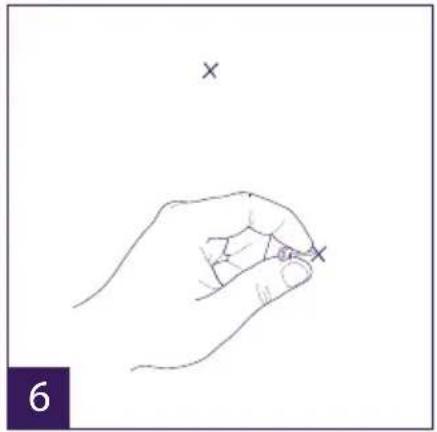
natural_image
Line drawing of a hand holding a pen with an 'x' mark above it, no text or symbols present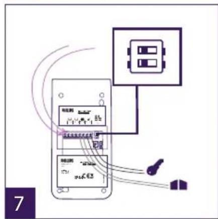
text_image
Diagram showing electrical connections between a device and a power outlet, with labeled components and wiring paths.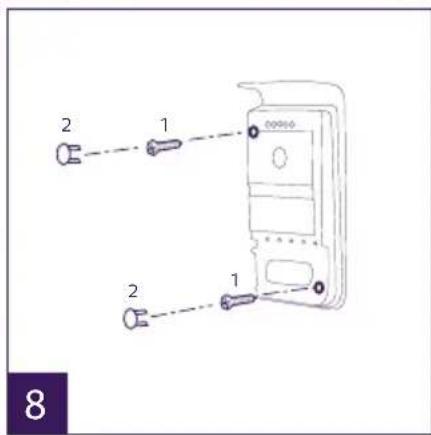
text_image
2 1 2 1 8
natural_image
Line drawing of a hand using a power tool to apply a digital device (no text or symbols visible)natural_image
Two purple square icons with white document and speech symbols, labeled 1 and 2 below (no text or numbers on icons)bar
| Stage | Start | Stop | |---|---|---| | Start | 21 | 07 | | Stop | 00 | 00 | a b c8. APLIKACJA NA SMARTFONY
text_image
UID xxxxxxxxxxxxxxxxx (1) Wirelessnatural_image
Simple line drawing of a rectangular electronic device with a screen and indicator block labeled 'PHILIPS' (no text or symbols on the device itself)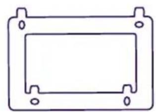
natural_image
Simple line drawing of a rectangular frame with mounting holes (no text or symbols)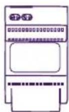
natural_image
Line drawing of a Philips electronic device with a circular button and control panel (no text or symbols on the device itself)


- 5 badge RFID:
natural_image
Hand holding a small component with a screwdriver, no text or symbols visible
natural_image
Line drawing of a hand holding a handheld tool with a probe, no text or symbols present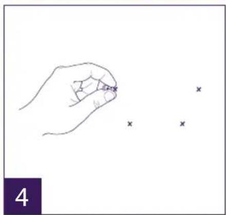
natural_image
Hand holding a small object with three small 'x' marks nearby (no text or symbols)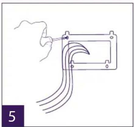
natural_image
Diagram of a hand holding a tool interacting with a mechanical component, showing curved lines and a bracket (no text or symbols)
natural_image
Diagram of a device with two connectors and connecting wires, no text or symbols present
text_image
7natural_image
Line drawing of a hand holding a smartphone with a screwdriver inserted (no text or symbols)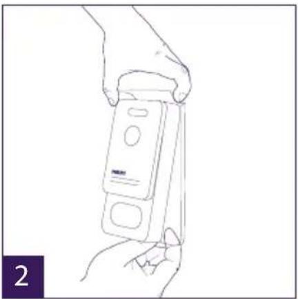
natural_image
Line drawing of a hand holding a handheld device (no text or symbols visible)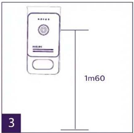
text_image
1m60 3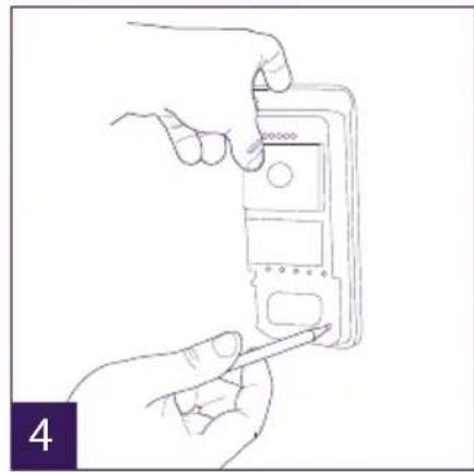
natural_image
Line drawing of hands inserting a card into a device (no text or symbols)
natural_image
Line drawing of a hand holding a handheld electric shaver (no text or symbols)
natural_image
Line drawing of a hand holding a pen with two 'x' marks above it, no text or symbols present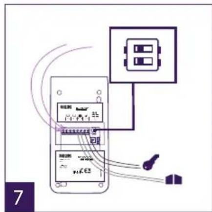
text_image
Diagram showing connections between a power supply unit and an electrical outlet with labeled components and wiring.
text_image
2 1 2 1 8
natural_image
Line drawing of a hand using a soldering iron to apply a solder pad to a device (no text or symbols visible)natural_image
Two purple square icons: one with two white document-like shapes, the other with a speech bubble (no text or symbols)1 2
text_image
Start 21 00 Stop 07 00 a b cheatmap
| | 23 | 59 | 01 | 31 | 2017 | |---|---|---|---|---|---| | | | | | | | | | | | | | | | | | | | | | | | | | | | | | | | | | | | | | | | | | | | | | | | | | | | | | | | | | | | | | | | | | | | | | | | | | | | | | | | | | | | | | | | | | | | | | | | | | | | | | | | | | | 01 | 31 | 31 | 31 | 31 | 31 | | 2017 | 31 | 31 | 31 | 31 | 31 | The chart is a heatmap with the same color coding for the x-axis (purple) and y-axis (dark purple). The values in the heatmap represent the absolute magnitude of each cell within the range of 23 to 59. The color legend is not explicitly labeled but corresponds to the color bar on the right.text_image
UID xxxxxxxxxxxxxxxxx (↓) Wireless ←
text_image
My apper. cp0407645text_image
Device! ANNEXION... OKB/1 Push to TalkWelcomeEye AddCompact: (monitor supplementare)
rif.: 531005
natural_image
Simple line drawing of a rectangular electronic device with a screen and indicator label (no text or symbols on the device itself)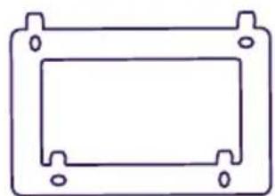
natural_image
Simple line drawing of a rectangular frame with mounting holes (no text or symbols)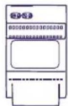
natural_image
Line drawing of a Philips electronic device with a circular button and control panel (no text or symbols on the device itself)- Placa externa

natural_image
Five simple oval shapes with small inner segments, arranged horizontally (no text or symbols)- 5 Llaves de proximi- dad RFID:
2 de usuario (gris)
1 admin (amarilla)
1 - (roja)
1 + (azul)
3. GENERALIDADES
natural_image
Pure electrical circuit lines without any symbolsnatural_image
Simple line drawing of a rectangular enclosure with six circular symbols on the front panel (no text or labels)natural_image
Hand holding a small component with a pointer, no text or symbols visible
natural_image
Line drawing of a hand holding a handheld tool with a probe, no text or symbols present
natural_image
Hand holding a pen with three small 'x' marks nearby (no text or symbols)
natural_image
Line drawing of a hand holding a tool next to a rectangular device with curved wires (no text or symbols)
natural_image
Diagram of a device with cable routing from an internal component (no text or symbols visible)
natural_image
Hand holding a tablet device with two arrows pointing downward (no text or symbols on device)natural_image
Line drawing of a hand holding a handheld device with a label 'GREEN PAPER' and a finger pointing to it (no text or symbols on the device itself)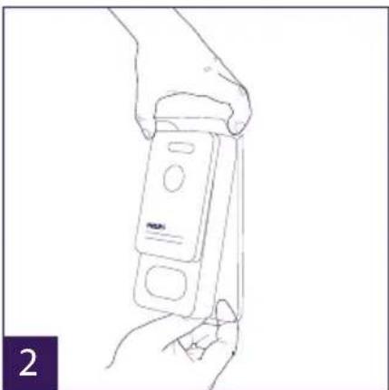
natural_image
Line drawing of a hand holding a handheld electronic device (no text or symbols visible)
text_image
1m60 3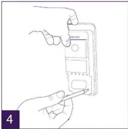
natural_image
Line drawing of hands inserting a card into a device (no text or symbols)
natural_image
Line drawing of a hand holding a handheld electric drill pen (no text or symbols)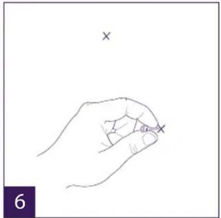
natural_image
Line drawing of a hand holding a small object with an 'x' mark above, no text or symbols present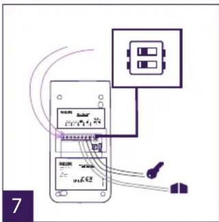
text_image
Diagram showing connections between a device with labeled components and a control panel, likely illustrating a system or system interface.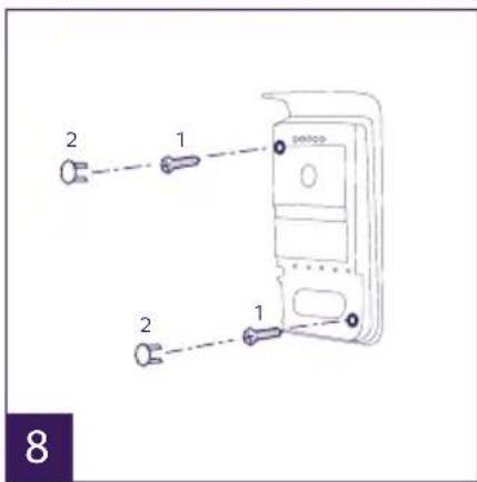
text_image
2 1 2 1 8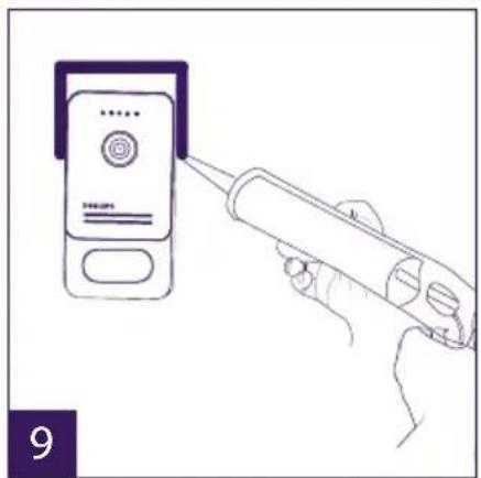
natural_image
Line drawing of a hand using a soldering iron to apply a power button to a device (no text or symbols visible)natural_image
Two purple square icons: one with two white document-like shapes, the other with a speech bubble (no text or symbols)1 2
text_image
Screenshot of a software interface with six icons: photo, video, image, musical note, and refresh symbol.
text_image
Mobile app interface screenshot showing status bar with music, music note, Wi-Fi, and refresh icons1 2 3 4 5 6 7 8 9 10 11
natural_image
Three colored square buttons with white icons: a small photo, a film strip, and an 'X' symbol (no text or labels)a
b
C
text_image
Start 21 00 Stop 07 00a
b
C
text_image
UID xxxxxxxxxxxxxxxxxxxx (↑) Wirelessnatural_image
Line drawing of a Philips monitor with no text or symbols on the device itself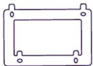
natural_image
Simple line drawing of a rectangular frame with mounting holes (no text or symbols)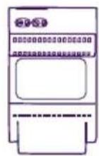
natural_image
Line drawing of a Philips electronic device with a circular button and control panel (no text or symbols on the device itself)- Placa de rua


5. 5 crachás RFID:
natural_image
Line drawing of a hand holding a small object with a pointer, no text or symbols present
natural_image
Line drawing of a hand holding a handheld tool with a probe, no text or symbols present
natural_image
Hand holding a pen with three small 'x' marks nearby (no text or symbols)
natural_image
Hand holding a tool interacting with a mechanical component, showing curved lines and a bracket (no text or symbols)
natural_image
Diagram of an electronic device with two connectors and a cable, no text or symbols present
natural_image
Line drawing of a hand holding a rectangular electronic device with a screen, above two downward arrows (no text or symbols)natural_image
Line drawing of a hand holding a handheld device with a label 'PANPLA' and a finger pointing to it (no text or symbols on the device itself)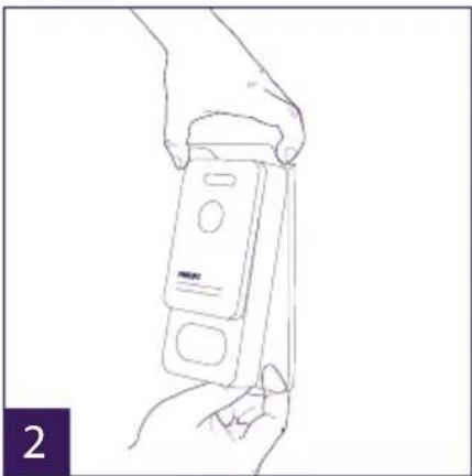
natural_image
Line drawing of a hand holding a handheld electronic device (no text or symbols visible)
text_image
1m60 3
natural_image
Line drawing of hands inserting a card into a device (no text or symbols)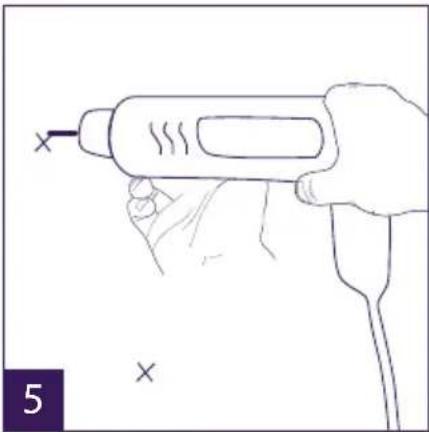
natural_image
Line drawing of a hand holding a handheld electric drill pen (no text or symbols)
natural_image
Line drawing of a hand holding a pen with an 'x' mark above it, no text or symbols present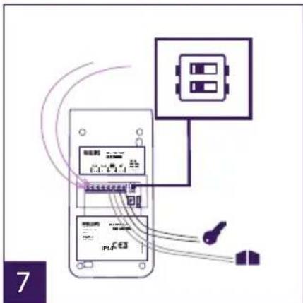
text_image
Diagram showing electrical connections between a device with labeled components and wiring, including a switch and battery.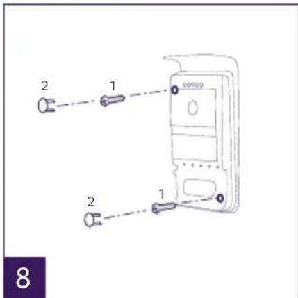
text_image
2 1 2 1 8
natural_image
Line drawing of a hand using a soldering iron to apply a power button to a device (no text or symbols visible)natural_image
Two purple square icons: one with two overlapping document shapes, the other with a speech bubble (no text or symbols)1 2
natural_image
Three purple square buttons with white icons: a small photo, a film strip, and an 'X' symbol (no text or labels)a
b
C
text_image
Start 21 00 Stop 07 00a
b
C
text_image
On UID XXXXXXXXXXXXXXXXX ( )
ref: 538102 (WelcomeEye Connect)
ref: 538101 (WelcomeEye Touch)
GB - Don't throw batteries or out of order products with the household waste (garbage). The dangerous substances that they are likely to include may harm health or the environment. Make your retailer take back these products or use the selective collect of garbage proposed by your city. Directive WEEE 2012/19/EU
GB - This symbol indicates that the device must only be installed and used indoors
GB - The protection of devices bearing this symbol is guaranteed by double insulation, they do not require a safety connection to electrical earth.
GB - Alternating Current
D - Wechselstrom
NL - Gelijkstroom
PL - Prąd zmienny