
RZX650 - Cash register SHARP - Free user manual and instructions
Find the device manual for free RZX650 SHARP in PDF.
| Product Type | Point of Sale Terminal (cash register) with touch screen |
| Brand | Sharp |
| Model | RZ-X650 |
| Dimensions (W × D × H) | 380 × 311 × 320 mm |
| Weight | 6.65 kg |
| Power Supply | AC/DC adapter 60W (12V/5A), rated voltage and frequency |
| Power Consumption | 60 W during operation |
| Processor | Intel Atom N270, 1.6 GHz |
| Hard Drive | 2.5-inch SATA, 160 GB |
| RAM | SODIMM 1 GB |
| Display | 15-inch (381mm) TFT-LCD color display, analog touch, XGA resolution (1024×768) |
| Adjustable Viewing Angle | 140° left/right, 45° up/down |
| Serial Ports | 3 COM ports (COM1/2/3), default PIN9 voltage = 5V |
| USB Ports | 2 USB connectors |
| VGA Output | 1 output for external display |
| Network Connector | 1 RJ45 Ethernet 10/100/1000 port |
| Audio Connector | 3.5 mm jack output |
| Parallel Port | 1 parallel port for printer |
| Cash Drawer Connections | 2 3-pin Molex ports |
| Magnetic Card Reader | Optional (model RZ-X6MR1) |
| Customer Display | Optional, 2-line (model RZ-X6DP1) |
| Operating Temperature | 5 to 35 °C |
| Noise Level | 37.3 dB(A) according to EN ISO 7779:2001; peak at drawer opening: 74.1 dB(A) |
| Maintenance and Cleaning | Unplug before cleaning; use a soft, dry cloth; do not use abrasive or liquid products. |
| Safety | Install away from direct radiation, temperature variations and humidity; do not block ventilation openings; unplug if not used for an extended period. |
| Spare Parts and Repairability | LCD screen and hard drive replaceable by a Sharp authorized technician; options installable by an authorized dealer. |
| Included Accessories | AC adapter and power cord |
Frequently Asked Questions - RZX650 SHARP
User questions about RZX650 SHARP
0 question about this device. Answer the ones you know or ask your own.
Ask a new question about this device
Download the instructions for your Cash register in PDF format for free! Find your manual RZX650 - SHARP and take your electronic device back in hand. On this page are published all the documents necessary for the use of your device. RZX650 by SHARP.
USER MANUAL RZX650 SHARP
Thank you very much for the purchase of a SHARP POS Terminal.
Please read this manual carefully before operating your POS Terminal.
Please keep this manual for future reference.
IMPORTANT
- Install this terminal in a location that is not subjected to direct radiation, unusual temperature changes, and high humidity or exposure to water or other liquids. Installation in such locations could cause damage to the cabinet and the electronic components.
- Do not drop this terminal nor subject it to any strong shock. This may cause damage to the terminal and the hard disk mounted in it.
- Do not apply excessive pressure to the display. Do not use a sharp-pointed object on the display.
- This may cause damage to the LCD display.
- The socket-outlet shall be installed near the equipment and shall be easily accessible. For a complete electrical disconnection, remove the AC plug from the wall outlet.
- The terminal plugs into any standard wall outlet (official / nominal voltage). Other electrical devices on the same electrical circuit could cause the terminal to malfunction.
- Slots and openings in the cabinet and the back have been provided for ventilation. To ensure the reliable operation of your system and protect it from overheating, these openings must not be blocked or covered.
-
Please observe the following when an optional drawer is used. The drawer units should be securely fitted to the supporting platform to avoid instability when the drawers are open.
-
Please shut down the terminal and disconnect it from the AC supply before connecting or disconnecting external devices to the COM ports. Note: Default voltage at Pin 9 of COM2 / COM3 is 5V.
FOR CUSTOMERS IN U.K.
IMPORTANT
The wires in this mains lead are coloured in accordance with the following code:
GREEN-AND-YELLOW: Earth
BLUE: Neutral
BROWN: Live
As the colours of the wires in the mains lead of this apparatus may not correspond with the coloured markings identifying the terminals in your plug, proceed as follows.
The wire which is coloured GREEN-AND-YELLOW must be connected to the terminal in the plug which is marked by the letter E or by the safety earth symbol or coloured green or green-and-yellow.
The wire which is coloured BLUE must be connected to the terminal which is marked with the letter N or coloured black.
The wire which is coloured BROWN must be connected to the terminal which is marked with the letter L or coloured red.
Ensure that your equipment is connected correctly - if you are in any doubt, consult a qualified electrician.
"WARNING: THIS APPARATUS MUST BE EARTHED."
Noise level: 37,3 dB(A) Measured according to EN ISO 7779:2001
[Maximum value if the optional cash drawer springs open: 74,1 dB(A)]
TABLE OF CONTENTS
SYSTEM OVERVIEW 4
DISPLAY 7
BEFORE CALLING FOR SERVICE 8
LIST OF OPTIONS 8
SPECIFICATIONS 9
Copyright
-
The copyright of this manual belongs to SHARP Corporation.
-
This manual may not be reproduced in whole or in part without the prior explicit permission of SHARP Corporation.
Trademarks
Intel is the registered trademark of Intel Corporation.
- Microsoft and Windows are registered trademarks of Microsoft Corporation.
- All other trademarks are the property of the respective company
SYSTEM OVERVIEW
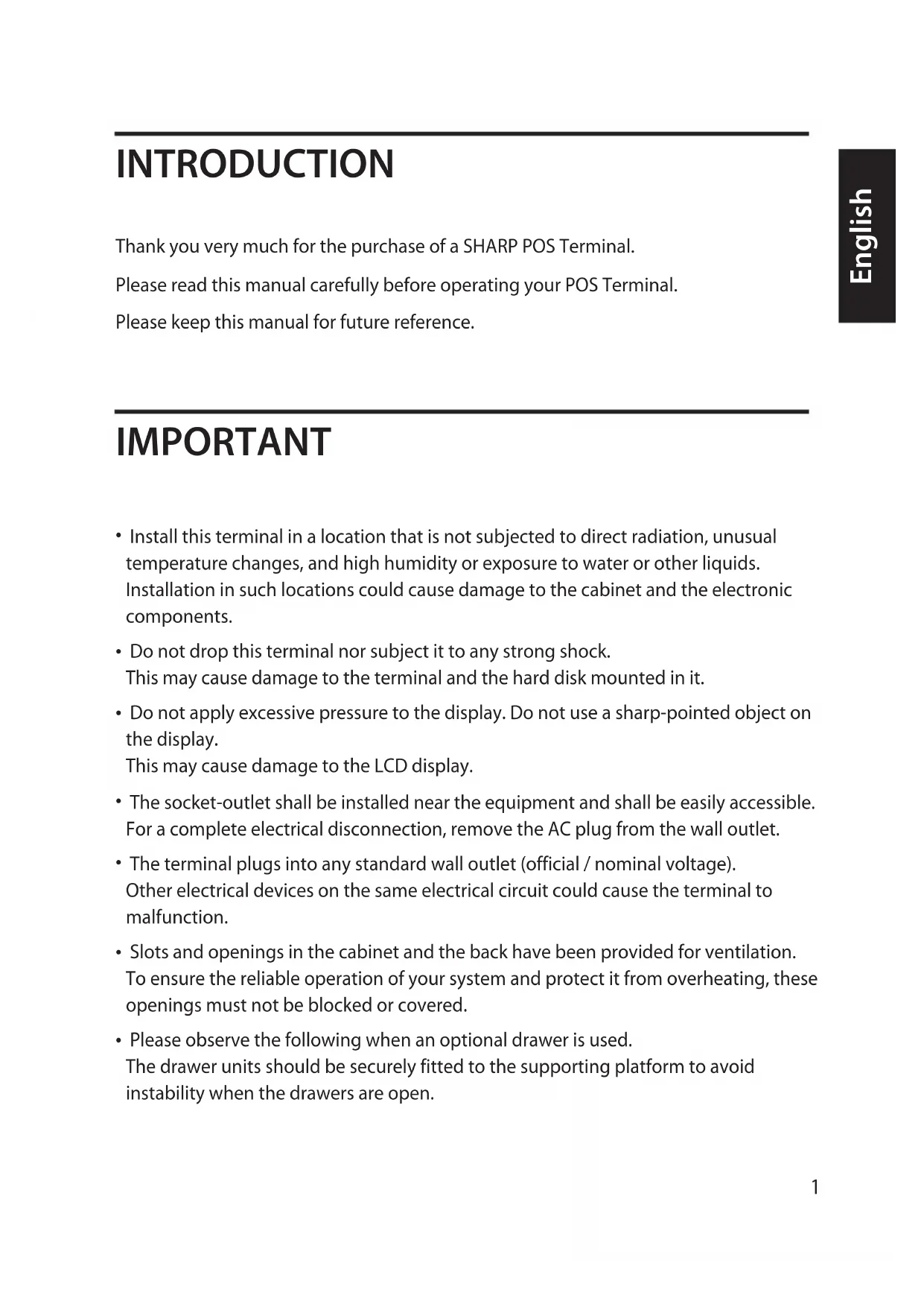
Front view
Operation Display (Touch Panel)
15 inch TFT-LCD screen with touch sensitive screen. Displays the operational status of the system and the system can be adjusted by touch screen.
2 Power button
After the terminal has been connected to the AC power supply push the power button to turn on the terminal.
3 HDD indicator
LED lights up when the hard disk drive is reading data from or writing data to the drive.
4 Power indicator
LED lights up when the system is on
5 LCD brightness control
For adjustment of the screens brightness. (increase / decrease)
6 Magnetic Strip Reader(Optional)
For reading magnetic stripe cards.
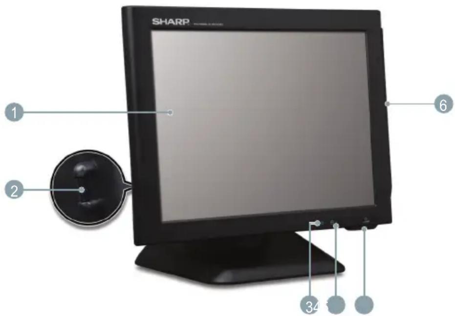
Rear/IO Ports view
Serial Port 1,2,3
Connects serial devices such as a customer display, a barcode scanner, or a receipt printer that use serial interface to the serial ports.
Note:
- Default voltage at Pin 9 of COM2 / COM3 is 5V. For further information, please contact your authorized SHARP dealer.
VGA Connector
Connects VGA signal cable from a 2^d monitor
3 USB connectors
You can connect peripherals such as scanners, printers and keyboard to the USB (Universal Serial Bus) connectors. USB peripherals are hot swappable enabling plug and play for your peripherals.
4 LAN connector (RJ 45)
Connects the RJ-45 cable for 10/100/1000 Base Ethernet connection to this port.
5 Audio jack
An external amplified speaker may be connected to the jack for listening to sounds.
DC inlet Jack (for AC adaptor)
To supply power to the system, please connect here the supplied AC/DC power adaptor (12V/5A).
DC outlet Jack (for future usage)
8 CashDrawerPorts(2\*3 pinMolex)
Optional Sharp cash drawers can be connected to the cash drawer port.
9 Parallel Port
Connect parallel devices such as a printer to the parallel port.
10 HDD rear cover
Remove the cover to install or replace the HDD. Consult your authorized SHARP dealer for further details.
DISPLAY
Display angle
The display may be tilted for the best viewing angle. The angle can be adjusted within 140 degrees left/right and 45 degrees up/down as illustrated in the picture.
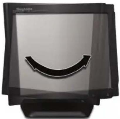
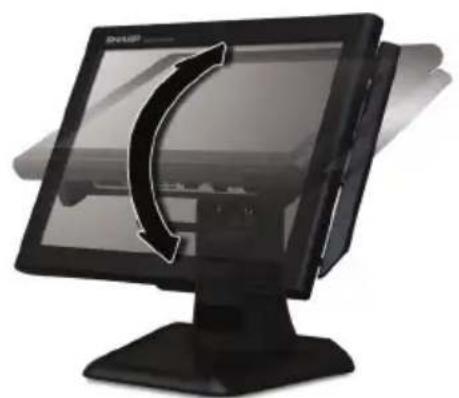
Caution:
- Do not pull the display beyond the maximum tilt angle nor apply excessive pressure to the display.
- Make sure to hold the body when pulling the display so that the terminal may not move.
- The LCD module built in this POS terminal is manufactured with highly precise technology, however bright pixels or blank pixels may appear. Also an irregular color and brightness may occur depending on the view angle. Please note that this type of phenomena is common for LCDs and may not be a malfunction.
- The backlight in the display is a consumable part.
- When the LCD display can no longer be adjusted and becomes darker, you should replace the LCD module. Consult your authorized SHARP dealer for further details.
BEFORE CALLING FOR SERVICE
The condition shown in the below left-hand column does not necessarily indicate functional faults of the terminal. Please check the listed items at the right-hand column "Checking" before calling for service.
| Condition Checking | |
| The power indicator is not lit. | • Is AC power available at the electrical outlet? • Is the AC plug of the AC/DC adapter connected to the electrical outlet? • Is the AC power cord disconnected or loosely connected to the AC/DC Adapter? • Is the AC adapters DC power cable connected to the DC inlet Jack of the POS terminal? • Is the power switch of the terminal turned “ON”? |
LIST OF OPTIONS
The following options are available for your POS terminal:
Do not try to install options yourself.
For details, contact your authorized SHARP dealer.
- Magnetic card reader model RZ-X6MR1
- 2 line rear customer display model RZ-X6DP1
- Remote drawer models ER-03DW/04DW/05DW/03DWB4/05DWB5
- The ER-48CC3 till is used for the ER-03DW/03DWB4
- The ER-48CC2 till is used for the ER-04DW
- The ER-58CC till is used for the ER-05DW/05DWB5
SPECIFICATIONS
| Model | RZ-X650 |
| External Dimensions | 380(W) × 311(D) × 320(H) mm |
| Weight | 6.65 kg |
| Power source | Official / nominal voltage and frequency |
| Power consumption | Operating: less than 60 W |
| Working temperature | 5 to 35 °C |
| CPU | Intel Atom N270 1.6GHz |
| Hard Disk | 2.5inch SATA 160GB |
| Memory | SODIMM 1GB |
| Display | Type: TFT Color LCD with backlight Analog touch panel Size: 381 mm (15inch) full screen Resolution: 1024 × 768 dots Control: XGA |
| AC / DC Adapter | 60W(12V/5A) |
| Accessories | AC Adaptor and AC cable |
- Specifications and appearance subject to change without notice for improvement.
EINLEITUNG

- IMPORTANT
- FOR CUSTOMERS IN U.K.
- TABLE OF CONTENTS
- Copyright
- Trademarks
- SYSTEM OVERVIEW
- Front view
- Operation Display (Touch Panel)
- Power button
- HDD indicator
- Power indicator
- LCD brightness control
- Magnetic Strip Reader(Optional)
- Rear/IO Ports view
- Serial Port 1,2,3
- Note:
- VGA Connector
- USB connectors
- LAN connector (RJ 45)
- Audio jack
- DC inlet Jack (for AC adaptor)
- DC outlet Jack (for future usage)
- CashDrawerPorts(2\*3 pinMolex)
- Parallel Port
- HDD rear cover
- DISPLAY
- Display angle
- Caution:
- BEFORE CALLING FOR SERVICE
- LIST OF OPTIONS
- SPECIFICATIONS
- EINLEITUNG
Brand : SHARP
Model : RZX650
Category : Cash register