
WMR200A - Weather Station OREGON SCIENTIFIC - Free user manual and instructions
Find the device manual for free WMR200A OREGON SCIENTIFIC in PDF.
| Product type | Professional weather station |
| Brand | Oregon Scientific |
| Model | WMR200A |
| Base station dimensions | 149 × 198 × 47 mm (L × W × H) |
| Base station weight | 510 g (without batteries) |
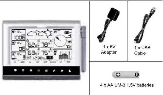
| Base station power supply | 4 AA 1.5V batteries or 6V AC adapter |
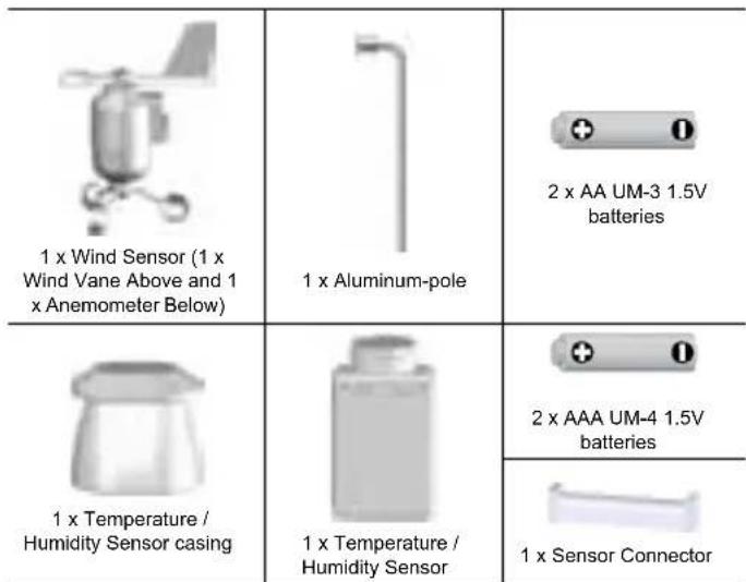
| Wind sensor power supply | 2 AA 1.5V batteries + solar panel |
| Outdoor temp/humidity sensor power supply | 2 AAA 1.5V batteries + solar panel |
| Rain gauge power supply | 2 AA 1.5V batteries |
| Display | LCD screen with backlight |
| Wireless range | Up to 100 meters (328 feet) in open area |
| Radio frequency | 433 MHz |
| Number of channels | 1 for wind/rain/UV, 10 for temperature/humidity |
| Main functions | Barometer, rainfall, UV, indoor/outdoor temperature, humidity, wind speed/direction, weather forecast, moon phase, alarms, max/min memory, data logger, PC connection |
| Indoor temperature range | 0 °C to 50 °C (32 °F to 122 °F) |
| Outdoor temperature range | -50 °C to 70 °C (-58 °F to 158 °F) |
| Relative humidity range | 2% to 98% |
| Barometer | Adjustable altitude, memory of last 24 hours |
| Rain gauge | Hourly and accumulated precipitation, memory of last 24 hours |
| UV index | 0 to 11+, with danger levels |
| Wind | Speed (gust/average) and direction, max gust memories |
| Clock | Radio-controlled atomic clock (WWVB-60), manual setting, moon phase |
| PC connection | USB, Weather OS software (Windows XP/Vista) |
| Maintenance and cleaning | Do not expose to moisture, clean with a soft cloth, do not use corrosive products |
| Spare parts and repairability | Additional sensors available (thermo-hygro, UV, pool probe) |
Frequently Asked Questions - WMR200A OREGON SCIENTIFIC
User questions about WMR200A OREGON SCIENTIFIC
0 question about this device. Answer the ones you know or ask your own.
Ask a new question about this device
Download the instructions for your Weather Station in PDF format for free! Find your manual WMR200A - OREGON SCIENTIFIC and take your electronic device back in hand. On this page are published all the documents necessary for the use of your device. WMR200A by OREGON SCIENTIFIC.
USER MANUAL WMR200A OREGON SCIENTIFIC
Professional Weather Center Model: WMR200 / WMR200A
USER MANUAL
CONTENTS
Introduction. 1
Packaging Contents 1
Base Station 1
Wind Sensor / Temperature & Humidity Sensor 1
Solar Panel 1
Rain Gauge. 1
Assembly Parts 2
Accessories - Sensors 2
Overview. 2
Front View 2
Back View 2
LCD Display 2
Detailed LCD Display View 2
Barometer 2
Rainfall 3
UV 3
Clock/Moon Phase 3
Outdoor Temperature / Humidity 3
Indoor Temperature / Humidity 3
Wind Speed / Direction / Wind Chill 3
BarChart. 3
Wind Sensor 4
Rain Gauge 4
Outdoor Temperature / Humidity Sensor 4
Getting Started. 4
Set Up Remote Wind Sensor 4
Set Up Remote Temperature / Humidity Sensor 4
Remote Unit Assembly 5
Alternative Set Up: Remote Wind Sensor On Existing Pole 6
Temperature / Humidity Sensor Mounted Separately 6
Set up Rain Gauge. 6
Getting Started. 7
Set up Base Station 7
Insert Batteries 7
Sensor Data Transmission 7
Clock. 7
Clock Reception 7
Manually Set Clock 7
Pressure 8
Set Altitude 8
Rainfall 8
Accumulated Rainfall 8
UV 8
Weather Forecast 8
Temperature and Humidity 8
Auto Scanning Function 8
Temperature and Humidity trends. 8
Heat Index 8
Wind 8
Moon Phase 8
BarChart 9
Alarm 9
Memory 9
MAX/MIN Records 9
Hourly Records 9
Data Logger 9
Set Up Software (First Time Use) 9
Additional step for Windows Vista users only 9
Install software 9
Disable Sleep Mode 10
To Disable Sleep Mode On Computer (Windows XP) 10
To Disable Sleep Mode On Computer (Windows Vista) 10
Upload data to PC software 10
Software updates. 10
Reset 10
Precautions 10
Specifications 10
About Oregon Scientific 11
EU-Declaration Of Conformity 11
FCC Statement 11
Declaration of Conformity 11
INTRODUCTION
Thank you for selecting the Oregon Scientific™ Professional Weather Center (WMR200 / WMR200A).
The base station is compatible with other sensors. To purchase additional sensors, please contact your local retailer.

NOTE Please keep this manual handy as you use your new product. It contains practical step-by-step instructions, as well as technical specifications and warnings you should know about.
PACKAGING CONTENTS
BASE STATION
WIND SENSOR/TEMPERATURE & HUMIDITY SENSOR
SOLAR PANEL
1 x Solar panel

1 x Solar panel connector
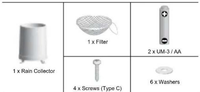
RAIN GAUGE
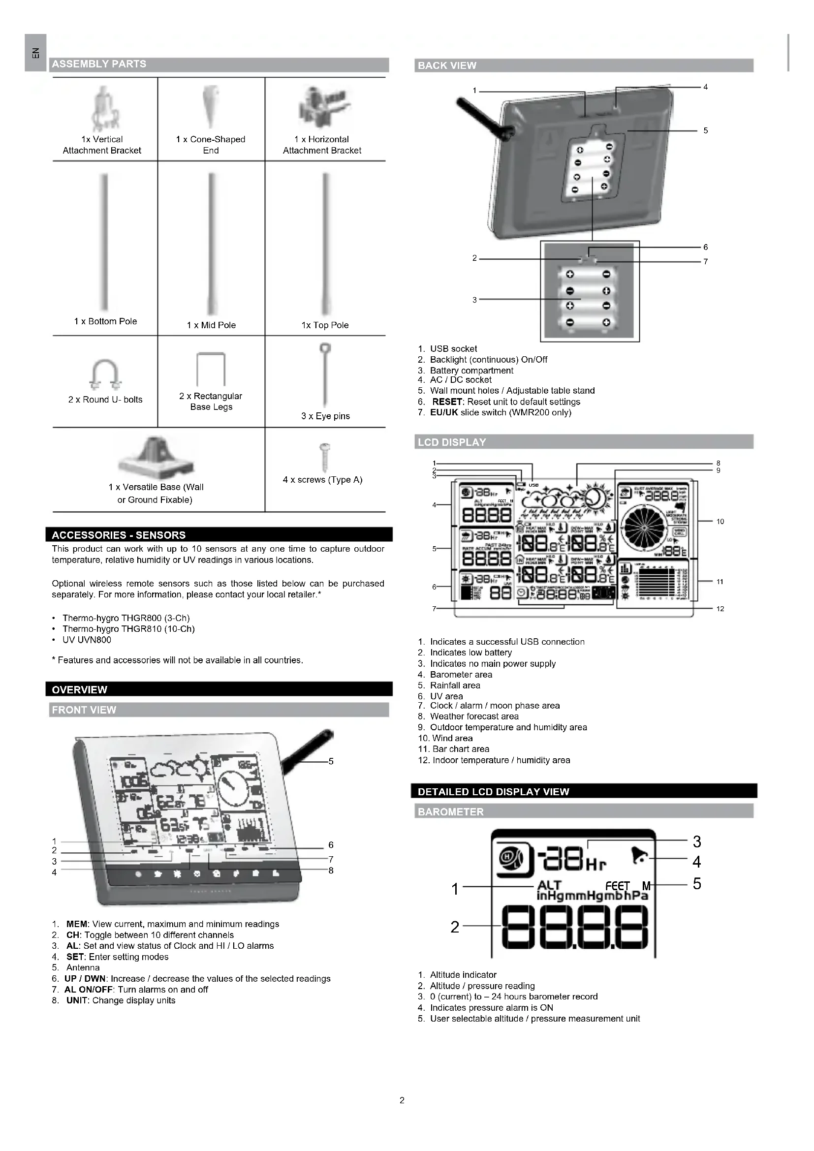
ASSEMBLY PARTS
| 1x Vertical Attachment Bracket | 1 x Cone-Shaped End | 1 x Horizontal Attachment Bracket |
| 1 x Bottom Pole | 1 x Mid Pole | 1x Top Pole |
| 2 x Round U- bolts | 2 x Rectangular Base Legs | 3 x Eye pins |
| 1 x Versatile Base (Wall or Ground Fixable) | 4 x screws (Type A) | |
ACCESSIONS - SENSORS
This product can work with up to 10 sensors at any one time to capture outdoor temperature, relative humidity or UV readings in various locations.
Optional wireless remote sensors such as those listed below can be purchased separately. For more information, please contact your local retailer.*
Thermo-hygro THGR800 (3-Ch)
Thermo-hygro THGR810 (10-Ch)
UV UVN800
* Features and accessories will not be available in all countries.
OVERVIEW
FRONTVIEW
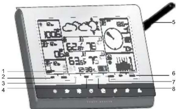
- MEM: View current, maximum and minimum readings
- CH: Toggle between 10 different channels
- AL: Set and view status of Clock and HI / LO alarms
- SET: Enter setting modes
- Antenna
- UP / DWN: Increase / decrease the values of the selected readings
- AL ON/OFF: Turn alarms on and off
- UNIT: Change display units
BACK VIEW
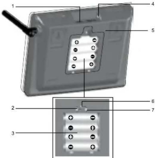
- USB socket
- Backlight (continuous) On/Off
- Battery compartment
- AC/DC socket
- Wall mount holes / Adjustable table stand
- RESET: Reset unit to default settings
- EU/UK slide switch (WMR200 only)
LGD DISPLAY
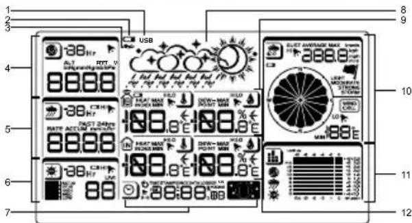
- Indicates a successful USB connection
- Indicates low battery
- Indicates no main power supply
4.Barometer area - Rainfall area
- UV area
- Clock / alarm / moon phase area
- Weather forecast area
- Outdoor temperature and humidity area
- Wind area
- Bar chart area
- Indoor temperature / humidity area
DETAILED LCD DISPLAY VIEW
BAROMETER
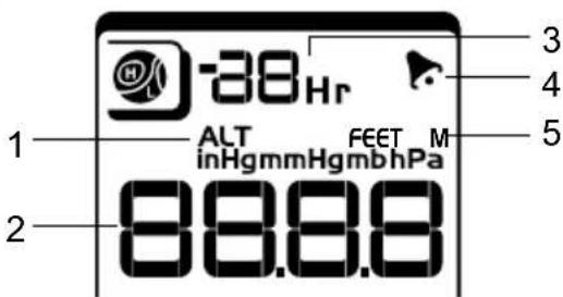
- Altitude indicator
- Altitude / pressure reading
- 0 (current) to -24 hours barometer record
- Indicates pressure alarm is ON
- User selectable altitude / pressure measurement unit
RAINFALL
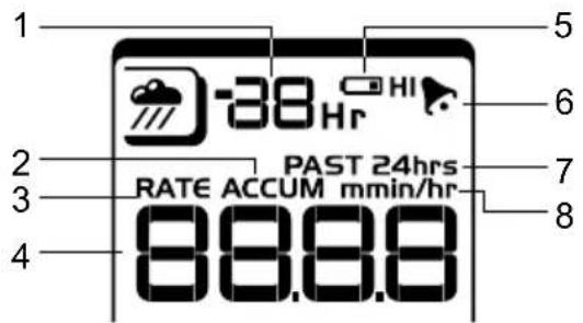
- 0 (current) to -24 hours rainfall record /
- Accumulated total rainfall (refer to SINCE date stamp in clock area for further details)
- Rain rate indicator
- Rain reading
- Sensor batteries low
- Indicates high rainfall alarm is ON
- Shows accumulated rainfall of past 24 hours
- Rainfall unit
UV
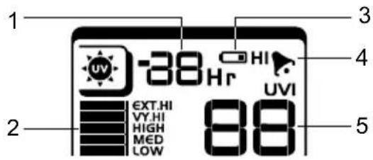
- 0 (current) to -10 hours UV record
- UV level index
- Sensor batteries low
- Indicates high UV alarm is ON
- UVI reading
CLOCK / MOON PHASE
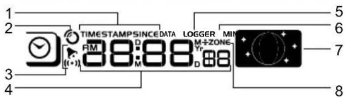
- Displays time of records, time stamp for Indoor / Outdoor temperature / humidity sensors and initial date set (Since date) for rainfall.
- Radio controlled clock
- indicates daily alarm is ON
- Displays Clock with seconds, Clock with day, Calendar, Data logger
- Data Logger displaying remaining number of days memory will allow for data collection
- Set Data Logging frequency (refer to Memory section)
- Moon phase display
- Offset time zone
OUTDOOR TEMPERATURE/HUMIDITY
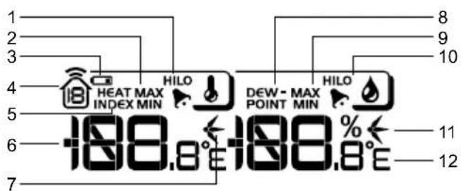
- Indicates HI / LO outdoor temperature alarms are ON
- MAX / MIN temperatures (refer to date stamp on clock area for more details)
- Sensor batteries low
- Displays from 1-10 outdoor sensors
- Heat index
- Outdoor Temperature readings
- Temperature trend indicators
- Dew point temperature
-
MAX/MIN humidity
-
Indicates HI / LO outdoor humidity alarms are ON
- Humidity trend indicators
- User selectable temperature units
INDOOR TEMPERATURE AND HUMIDITY
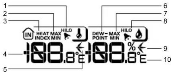
- Indicates HI / LO temperature alarms are ON
- MAX/MIN temperatures
- Heat index
- Indoor temperature reading
- Temperature trend indicators
- Dew point temperature
- MAX/MIN indoor humidity
- Indicates HI / LO humidity alarms are ON
- Humidity trend indicators
- User selectable temperature units
- User selectable measured winds: Gust / Average; Displays MAX wind speeds recorded
- Indicates HI alarm is ON
- Sensor batteries low
- Wind direction indicator
- User selectable wind speed units
- Wind speed level indicator
- Wind chill temperature display
- Indicates LO windchill alarm is ON
- Windchill reading
BAR CHART
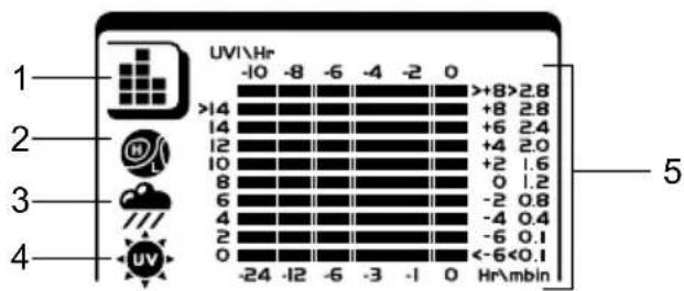
- Bar chart icon area
2.Barometer bar chart display - Rainfall bar chart display
- UV bar chart display
- Measurement axis
WIND SENSOR
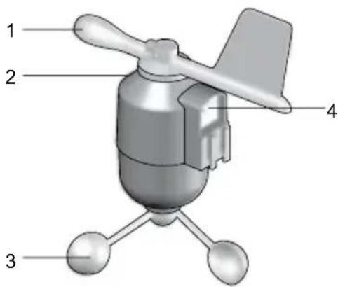
- Wind Direction
- Wind vane casing
- Anemometer
- Solar power socket
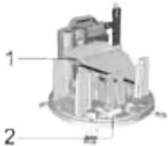
RAIN GAUGE
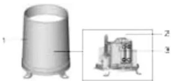
Base and funnel:
- Rain Gauge
- Battery compartment
- RESET button
- Funnel
- Indicator
OUTDOOR TEMPERATURE/HUMIDITY SENSOR
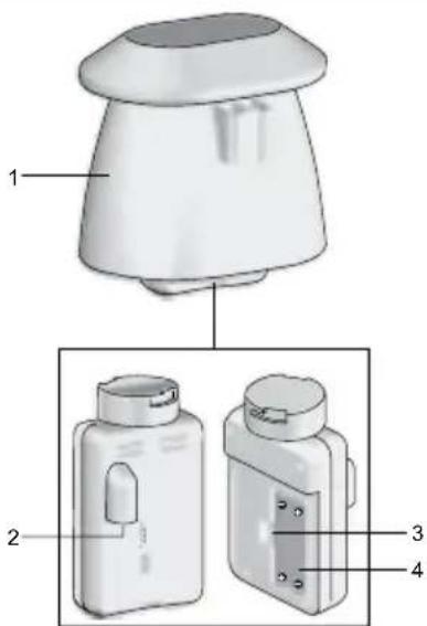
- Temperature / humidity sensor casing
- Solar power socket
- RESET button
- Battery compartment
GETTING STARTED
SET UP REMOTE WIND SENSOR
The wind sensor takes wind speed and direction readings.
The sensor is battery and solar powered operated. It is capable of transmitting data to the base station wirelessly within an approximate operating range of 100 meters (328 feet).
IMPORTANT Ensure that the wind sensor is pointing North to enable it to record accurate readings.
NOTE The sensor should be positioned in an open area away from trees or other obstructions.
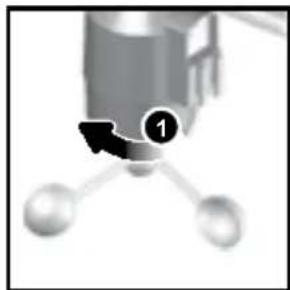
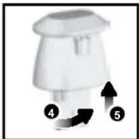
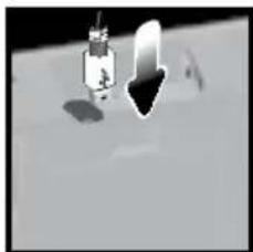
To insert batteries:
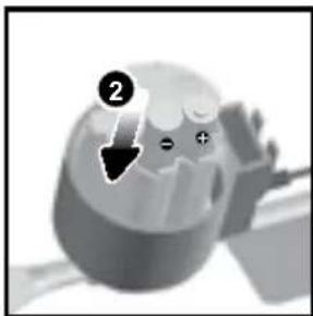
- Unscrew the anemometer from the wind sensor carefully.
- Insert batteries matching the polarities (+/-) and replace the anemometer. Press RESET after each battery change.
- Slide wind vane onto the end of the plastic attachment located on the aluminium pole.
NOTE Use alkaline batteries for longer usage and consumer grade lithium batteries in temperatures below freezing.
SET UP REMOTE TEMPERATURE/HUMIDITY SENSOR
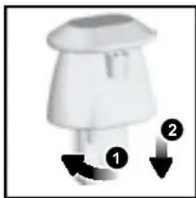
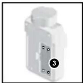
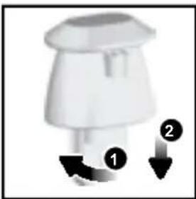
- Holding sensor, twist and click to the left.
- Pull sensor away from casing
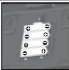
- Insert batteries matching the polarities (+ / -). Press RESET after each battery change.
- Insert sensor into the casing, twist and click to the right to secure.
- Slide temperature and humidity sensor onto the smaller end of the sensor connector.
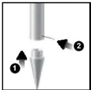
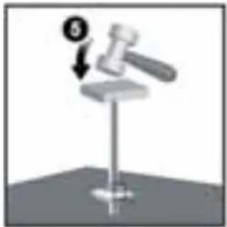
- Insert the cone-shaped end into the pole.
- Using 2 screws, fix it firmly into place.
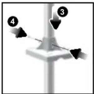
- Insert the versatile plastic base into the pole. Align the holes of the pole with the holes of the plastic base.
- Secure the plastic base by inserting the screw and screwing it tightly into the holes of the plastic base and pole.
IMPORTANT The sensor should be positioned in an open area away from trees or other obstructions.
- Hammer pole (cone end down) into the ground at the desired spot until versatile plastic base is level with the ground.
TIP Place a block of wood between the pole and the hammer to prevent damage to the pole.
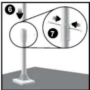
- Assemble middle pole on top of the bottom one.
- Using two screws, fix it firmly into place.
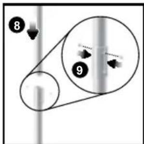
- Assemble top pole on top of the middle one.
- Using two screws, fix it firmly into place.
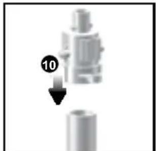
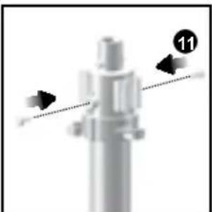
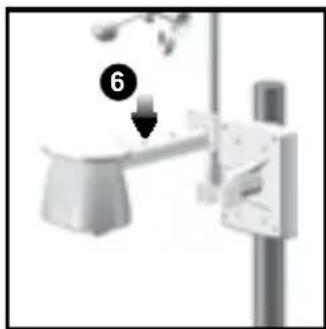
- Slide the vertical attachment bracket on top of the top pole.
- Using two screws, fix it firmly into place.
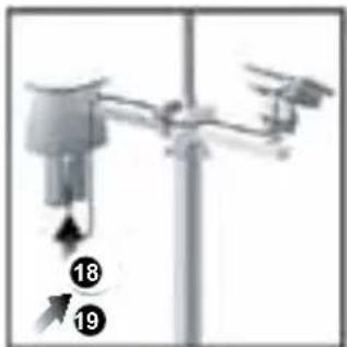
To mount the temperature / humidity sensor:
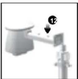
- Slide outdoor sensor onto vertical attachment bracket.
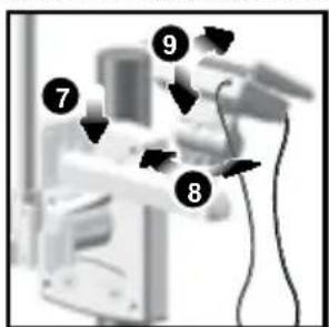
- Slide the solar panel connector into place on the opposite side of the bracket. Slot the solar panel in place.
- Adjust the solar panel. Once facing desired direction, use screw to fix in place.
- Loosen the wing bolt and adjust the angle. Tighten wing bolt to secure solar panel at desired angle.
NOTE For best results, direct solar panel as follows:
| Solar panel facing: if you reside | in the: |
| North Southern Hemisphere | |
| South Northern Hemisphere |
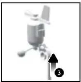
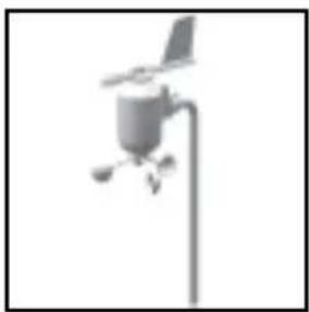
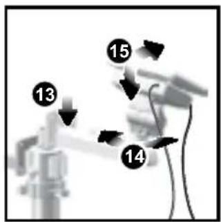
To mount the wind sensor:
- Insert the wind vane into the attachment bracket.
- Screw aluminum pole firmly into place.
IMPORTANT For best results, point the wind vane North.
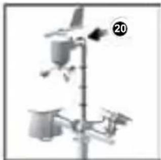
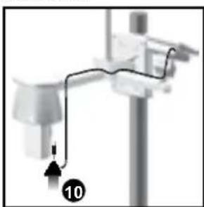
- Remove outdoor sensor from casing. Plug one solar panel cable into the socket.
- Replace sensor into the casing.
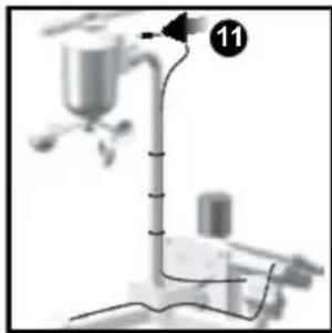
- Plug the other solar panel cable into the socket on the wind vane.
This will provide the sensors with an additional power supply.
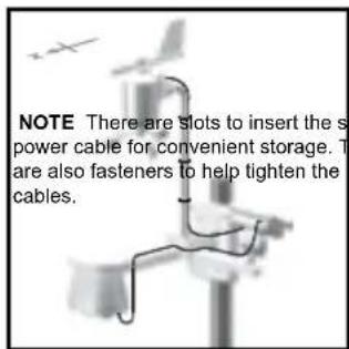
NOTE There are slots to insert the solar power cables for convenient storage. There are also fasteners to help tighten the cables.
NOTE The solar panel is an energy saving feature, which is an environmentally friendly way to provide additional power to the sensors and prolongs battery life. However, it cannot replace battery power entirely. Sensors can operate entirely on battery power.
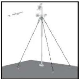
Securing the assembled remote unit:
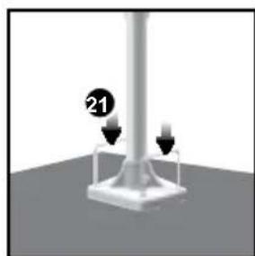
-
Insert the 2 rectangular base legs through the holes of the versatile base and hammer down.
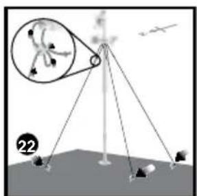
-
Using the string, tie a knot on the eye pins. Hammer each eye pin into the ground at a 90^ angle.
IMPORTANT Using the fasteners, tighten the string. To tighten, pull fastener down.
To loosen, thread the string up through the fastener eyelets
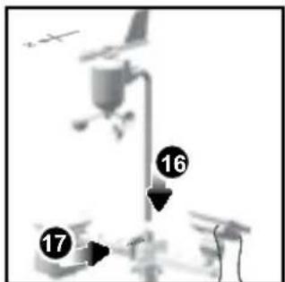
ALTERNATIVE SET UP: REMOTE WIND SENSOR ON EXISTING POLE
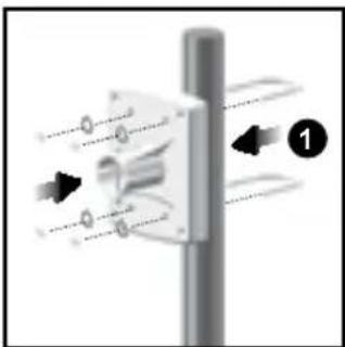
- Secure the plastic base onto existing pole with U-bolts, washers and bolts.
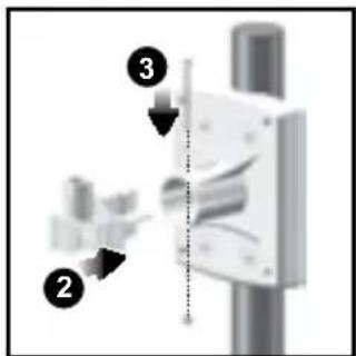
- Insert the horizontal attachment bracket into the base.
- Using a screw, fix firmly into place.
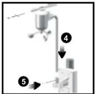
- Insert wind sensor into the top of the bracket.
- Using screws, fix aluminum pole firmly into place
- Slide outdoor sensor onto bracket.
IMPORTANT For best results, point the wind vane North.
- Slide the solar panel connector into place on the other side of the bracket. Slot the solar panel in place.
- Adjust the solar panel. Once facing desired direction, use screw to fix in place.
- Loosen the wing bolt and adjust the angle. Tighten wing bolt to secure solar panel at desired angle.
- Remove outdoor sensor from casing. Plug one solar panel cable into the socket. Replace sensor into the casing.
NOTE For best results, direct solar panel as follows:
Solar panel facing: If you reside in the:
| North Southern Hemisphere | |
| South Northern Hemisphere |
11. Plug the other solar panel cables into the socket on the wind vane.
ALTERNATIVE SET UP: TEMPERATURE/HUMIDITY SENSOR MOUNTED SEPARATELY
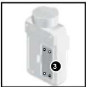
- Insert 4 type A screws into the holes of the sensor connector. Screw firmly into place, i.e., fence.

SETUPRAINGAUGE
The rain gauge collects rain and takes readings of rainfall rate and the total rainfall over a period of time. The sensor can remotely transmit data to the base station.
The base station and rain gauge should be positioned within an effective range: about 100 meters (328 Feet) in an open area.
The rain gauge should be mounted horizontally about 1 meter (3 feet) from the ground in an open area away from trees or other obstructions to allow rain to fall naturally for an accurate reading.
To set up the Rain Gauge:
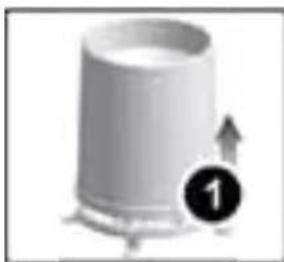
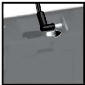
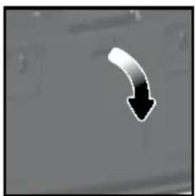
- Remove screws and slide the cover off in an upwards motion.
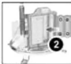
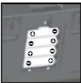
- Insert the batteries (2 x UM-3 / AA), matching the polarities (+/-). Press RESET after each battery change.
3. Remove the fibre tape.
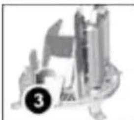
To ensure a level plane:
Put a few drops of water on the cross at the base of the funnel to check the horizontal level.
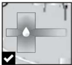
Water will pool to the center of the cross when the rain gauge is level.
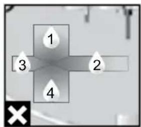
If water remains on 1-4, the gauge is not horizontal.
If necessary, adjust the level using the screw.
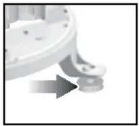
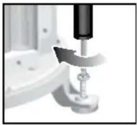
NOTE For best results, ensure the base is horizontal to allow maximum drainage of any collected rain.
GETTING STARTED
SETUPBASESTATION
NOTE Install batteries matching the polarities (+ / -) in the remote sensor before installing the base station.
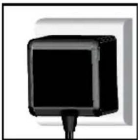
For continuous use, install the AC adapter. The batteries are for back-up use only. NOTE: Make sure the adapter is not obstructed and is easily accessible to the unit
NOTE: The base station and adapter should not be exposed to wet conditions. No objects filled with liquid, such as vases, should be placed on the base station and adapter.
INSERT BATTERIES
- Remove the battery compartment.
- Insert the batteries, matching the polarities (+/ -).
- Press RESET after each battery change.
NOTE Do not use rechargeable batteries. It is recommended that you use alkaline batteries with this product for longer performance.
NOTE Batteries should not be exposed to excessive heat such as sunshine or fire.
| LOCATION | MEANING |
| Weather forecast area Base station batteries | low |
| Rainfall / UV / Wind / Outdoor temperature / humidity area | Sensor batteries low |
SENSOR DATA TRANSMISSION
To search for a sensor:
- Select desired area to activate.
- Press and hold CH and MEM.
icons will flash for 5 minutes.
NOTE Unit will search only for already registered sensors or new sensors reset within last 30 minutes. To register a new sensor, reset sensor prior to search.
The sensor reception icon in the remote sensor area shows the status:
| ICON DESCRIPTION | |
| Base station is searching for sensor(s) | |
| A channel has been found | |
| Sensor 1 data received | |
| The sensor cannot be found. | |
TIP The transmission range may vary depending on many factors. You may need to experiment with various locations to get the best results.
CLOCK
CLOCK RECEPTION
This product is designed to synchronize its clock automatically with a clock signal.
WMR200:
Slide switch to EU/UK to select the desired signal.
EU: DCF-77 signal: within 1500km (932 miles) of Frankfurt, Germany.
UK: MSF-60 signal: within 1500km (932 miles) of Anthorn, England.
WMR200A:
WWVB-60 signal: within 3200km (2000 miles) of Fort Collins Colorado. Manually set clock to select time zone (Pacific, Mountain, Central or Eastern).

states the status of the clock reception signal.
| ICON MEANING | |
| Time is synchronized Receiving signal is strong | |
| Time is not synchronized Receiving signal is weak | |
NOTE Reception takes 2-10 minutes. If the signal is weak, it can take up to 24 hours to get a valid signal.
To enable / disable signal reception:
Press and hold clock area to enable / disable signal reception. A beep will sound to confirm action.
NOTE For best reception, the base station should be placed on a flat, non-metallic surface near a window in an upper floor of your home. The antenna should be placed away from electrical appliances and not be moved around when searching for a signal.
MANUALLY SET CLOCK


- Press clock area to activate.
- Press SET to toggle between time zone offset, 12/24 hr format, hour, minute, year, day / month, month, day, time zone.
- Once in desired setting, press UP or DWN to change the settings.
-
Press:
-
SET to confirm and continue to next setting OR
-
touch panel area (except tool bar) to confirm and exit.
WMR200: Time zone offset sets the clock +/- 23 hours from the received clock signal time.
WMR200A: Select the time zone: (PA) Pacific, (EA) Eastern, (CE) Central or (MO) Mountain.
NOTE The language options are English (E), German (D), French (F), Italian (I), and Spanish (S).
Press clock area repeatedly to toggle between:
Clock with seconds
Clock with weekday
- Date with year
Data logger (please refer to Memory / Data logger section)
PRESSURE
To toggle barometer unit:
- Press barometer area to toggle between Altitude / current barometer.
- Press UNIT to select FEET / M or inHg / mmHg / mb / hPA.
SET ALTITUDE
Set the altitude to reflect distance from sea level at your position.
- Press barometer area display ALT.
- Press SET.
- Press UP / DWN to set the altitude in 10 m (33 ft) increments from -100 m (-328 ft) to 2500 m (8202 ft).
- Press SET or touch panel area (except tool bar / forecast area) to confirm.
RAINFALL
To select rainfall display mode:
Press rain area to toggle between:
- Rain rate
- Hourly Rainfall
- Accumulated rainfall
Rainfall recorded in the past 24 hours
Press UNIT to select mm / in.
ACCUMULATED RAINFALL
To display SINCE DATE:
- Press rain area repeatedly until Accumulated Rainfall is displayed. (Clock area will display the start date / time of rainfall recording).
To reset SINCE DATE:
Press and hold MEM to set current time as start of accumulated rainfall records.
The UV index levels are as follows:
UV
| UV INDEX DANGER LEVEL ICON | ||
| 0-2 Low | LOW | |
| 3-5 Moderate | MED | |
| 6-7 High | HI | |
| 8-10 Very high | V.HI | |
| 11 and above Extremely high | EX.HI | |
WEATHER FORECAST
This product forecasts the next 12 to 24 hours of weather within a 30 - 50km (19-31 mile) radius (US- with a 75% accuracy).
| Sunny | |
| Clear night | |
| Partly cloudy | |
| Partly cloudy at night | |
| Cloudy | |
| Rainy | |
| Snowy |
TEMPERATURE AND HUMIDITY
To toggle temperature unit:
-
Press Indoor / Outdoor Temperature / Humidity area.
-
Press UNIT to select ^ C / F
To auto-scan between sensors (Outdoor):
- Press Outdoor Temperature / Humidity area.
- Press and hold CH to display data for each sensor.
AUTO SCANNING FUNCTION
To activate the outdoor temperature and humidity auto-scan function:
- Press and hold CH to activate auto-scan. The temperature and humidity display will scroll from indoor to ch1 through to ch10.
- Press CH / MEM to stop the auto-scan.
NOTE Channel 1 is used for the outdoor temperature and humidity sensor provided in this package. Additional temperature and humidity sensors can use other channels.
To change channel:
Press CH to change channel.
TEMPERATURE AND HUMIDITY TRENDS
The temperature and humidity trend icons are based on recent sensor readings.
The trend lines are shown next to the temperature and humidity readings. The trend is shown as follows:
HEAT INDEX
| TEMPERATURE RANGE | WARNING MEANING | |
| 27°C to 32°C(80°F to 89°F) | Caution | Possibility of heat exhaustion |
| 32°C to 40°C(90°F to 104°F) | Extreme Caution | Possibility of heat dehydration |
| 41°C to 54°C(105°F to 129°F) | Danger | Heat exhaustion likely |
| 54°C to 92°C(130°F to 151°F) | Extreme danger | Strong risk of dehydration / sun stroke |
NOTE Heat index is only calculated when temperature is 80^ / 27^ or above.
To select wind display mode:
Press wind area to toggle between:
Gust Average
Press UNIT to select unit: knots / kph / mph / m/s.
The wind level is shown by a series of icons:
| Lost sensor | Light | Moderate | Strong | Storm |
| 0-8 mph (3-13 km/h) | 9-25 mph (14-41 km/h) | 26-54 mph (42-87 km/h) | >55 mph (>88 km/h) | |
| I |
MOON PHASE
| 1. Press clock area to activate. 2. Press SET repeatedly to display Year / Calendar date. 3. Press UP / DWN to view moon phase for specific dates. | |||
| New Moon | Full Moon | ||
| Waxing Crescent | Waning Gibbous | ||
| First quarter | Last quarter | ||
BAR CHART
To select chart display mode:
Press bar chart area to toggle between these chart displays:
Barometer
Rain
UV
ALARM
Weather alarms are used to alert you of certain weather conditions. Once activated, the alarm will turn off when a certain criterion is met.
| Area | Type of alarm | |
| Barometer | Barometer | HI |
| Rain | Rain rate | HI |
| UV UV | HI | |
| Temperature | Current Temperature | HI |
| LO | ||
| Heat Index | HI | |
| Humidity | Current Humidity | HI |
| LO | ||
| Dew Point | HI | |
| LO | ||
| Clock | Daily Alarm | |
| Wind | Gust Wind Speed | HI |
| Low Wind Chill | LO |
To set the alarm:
- Press desired area to activate.
- Press AL to display Time and HI / LO alarm.
- Press and hold AL
- Press UP / DWN to set the desired values.
- Press
AL to confirm and continue to next setting OR
- touch anywhere on the screen (except tool bar / weather forecast area) to
confirm and exit.
To enable / disable alarms:
- Press desired area to activate.
- Press AL to display set Time and HI / LO alarm.
- Press AL ON/OFF to turn alarm ON / OFF.
--" indicates alarm is not set / disabled.
NOTE Clock alarm sound is different from weather alarms to allow for easy differentiation by user.
To silence any alarm: Press anywhere on the screen.
NOTE will continue flashing, despite silenced alarm, for at least 2 minutes or until condition ceases.
NOTE When alarm is on, the channel of triggered alarm will be displayed.
MEMORY
MAX/MIN RECORDS
| Area | Type of Memory | |
| Temperature | Current Temperature | MAX |
| MIN | ||
| Heat Index | MAX | |
| MIN | ||
| Humidity | Current Humidity | MAX |
| MIN | ||
| Dew Point | MAX | |
| MIN | ||
| Wind Gust Wind Speed | MAX | |
| Wind Chill | MIN |
To view MAX / MIN records:
- Press desired area to activate.
- Press MEM to toggle between MIN/MAX recorded values
To clear individual area records:
- Press desired area to activate.
- Press and hold MEM.
- Delete process is complete when display shows current reading.
HOURLY RECORDS
| Display Hourly readings of up to | |
| Barometer 24 hours back | |
| Hourly Rainfall 24 hours back | |
| UV 10 hours back |
To view hourly records:
- Press desired area to activate.
- Press UP / DWN to view current (0) / hourly reading.
When MAX / MIN reading is displayed, the corresponding timestamp will be

DATA LOGGER
To set DATA LOGGER:
- Press clock area until DATA LOGGER mode is displayed.
- Press SET
- Press UP / DWN to select frequency of data recording (1/2/5/10/15).
- Press SET
- The number of days memory will allow for records will be displayed.
| Frequency in minutes | No. of days available for data logging with Memory available* |
| 1 | 19 |
| 2 | 38 |
| 5 | 97 |
| 10 194 | |
| 15 291 |
- based only on all provided sensors in this package being used, and after all memory has been cleared.
To view remaining days for records:

until DATA LOGGER mode is displayed.
NOTE When DATA LOGGER is full, i.e., no more records can be stored on unit, 'DATA LOGGER' and 'O Days' will flash.
SETUPSOFTWARE(FIRSTTIMEUSE)
The weather station is capable of connecting to a PC computer using the USB connection. The software can read the latest weather data collected from the base station.
PC system requirements
The minimum system requirements for use of the software is:
- Operating system: Microsoft Windows XP SP2 or Vista
- Processor: Pentium 4 or above
RAM:Min.512MB
Hard disk free space: Min. 512 MB
Screen Display Area:1024 x 768 pixels (recommended)
ADDITIONAL STEP FOR WINDOWS VISTA USERS ONLY
*For Windows XP users, please go straight to Install Software section.
IMPORTANT You must follow the below instructions before installing software.
Determine status of UAC (User Account Control):
- Click on Start.
- In context menu, scroll to Settings and select Control Panel.
- Double click the User Account (and Family Safety).
- Double click on Change your Windows password. (If you chose the Control Panel classic link from left hand column in step 2, skip this step).
- In Turn User Account On or Off screen, identify if UAC option is enabled / on (ticked) or disabled / off (un-ticked).
NOTE We highly recommend disabling this option for seamless operation of the Weather OS software.
To Turn User Account off:
- Deselect the UAC option by un-ticking the box (click once).
- Click OK.
- In You must restart your computer dialogue box, click Restart now.
INSTALL SOFTWARE
- Insert provided CD into disk drive.
- Run CD software.
- Setup Wizard dialogue box will appear and guide you through the installation process.
If you have Windows Vista and User Account Control is ON (ticked):
i. In Select Installation Folder dialogue box, next to Folder text box (C:\Program Files\Oregon Scientific\Weather OS), click Browse.
ii. To select a new location to save the program, select C:\Users\admin. {Or click C: Drive, subfolder Users, subfolder admin.}
iii. Click on (Create New Folder) icon.
iv. Type OS Weather and click OK.
v. In User Account Control dialogue box, click Allow.
vi. Continue with installation process.
4. During installation, Microsoft Visual C++ Redistributable Setup dialogue box may appear. Select Repair and click Next.
5. Once Setup has been successfully completed, click Finish, then Close.
6. After successful installation, double click on desktop shortcut.
7. Click Display in Oregon Weather Station dialogue box.
DISABLE SLEEP MODE
To allow for continuous data updates, ensure Sleep Mode on computer is disabled.
TO DISABLE SLEEP MODE ON COMPUTER (WINDOWS XP)
- Right click on Desktop
- In context menu, click on Properties.
- Click on Screen Saver tab in the Display Properties dialogue box.
- Click on Power located at the bottom half of dialogue box.
- In new dialogue box Power Options Properties, click on Power Schemes tab.
- In Settings for Timers off (Presentation) power scheme section, under System Standby option, choose Never in drop-down list.
- Click Apply and then click OK.
- Previous window will return. Click OK to confirm and exit.
TO DISABLE SLEEP MODE ON COMPUTER (WINDOWS VISTA)
- Right click on Desktop
- In context menu, click on Personalize.
- Click on Screen Saver link in the Personalize appearance and sounds dialogue box.
- Click on Change Power Settings located at the bottom half of window.
- Select High Performance and click Change plan settings link.
- Click Change advanced power settings link.
- Click on next to Sleep, in sub menu, click on next to Hlbernate after.
- Click Setting link and select Never in drop-down list.
- Click Apply and then OK.
UNPGLOAD DATA TO PC SOFTWARE
NOTE The USB is only used for uploading weather data. It cannot be used for charging battery power.
- After successful installation, double click on desktop shortcut.
- Click Display in Oregon Weather Station dialogue box.
- You will be prompted to select model number. Please select your model in the drop-down list and refer to the image next to your selection to confirm it is the correct model.
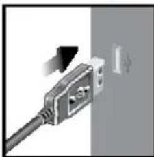
- Plug one end of the USB cable into the base station's USB port and the other end into the PC's USB port.
- Uploading will start immediately.
NOTE This product should be supplied by an identical USB port complying with the requirements of Limited Power Source.
To clear records from the base station:

until DATA LOGGER is displayed.
- Press and hold MEM
- All LED icons will light up and turn off consecutively (right to left). Delete process is complete and successful after blinking of last icon
To learn more about how to utilize the functions available on the software, please refer to PC Software Manual, downloadable from the software webpage.
IMPORTANT You must first successfully install software to access the PC Software Manual.
- In the PC software homepage, click on MENU located at the top right hand corner of software main webpage.
- Select HELP from drop-down list. This will redirect you to a new webpage. Click on PC Software Manual.
SOFTWARE UPDATES
As we continually strive for improvement, the software will be updated from time to time.
If there is a new version, the moment PC is connected to the internet, a dialogue box informing of available software will appear.
- Click OK.
- After a few moments, File Download - Security Warning dialogue box will appear. Click Run.
- In the Internet Explorer - Security Warning, click Run.
- Follow steps 3 - 7 from Install Software section.
RESET
Press RESET to return to the default settings.
PRECAUTIONS
- Do not subject the unit to excessive force, shock, dust, temperature or humidity.
- Do not cover the ventilation holes with any items such as newspapers, curtains etc.
- Do not immerse the unit in water. If you spill liquid over it, dry it immediately with a soft, lint-free cloth.
- Do not clean the unit with abrasive or corrosive materials.
- Do not tamper with the unit's internal components. This invalidates the warranty.
- Only use fresh batteries. Do not mix new and old batteries.
Images shown in this manual may differ from the actual display. - When disposing of this product, ensure it is collected separately for special treatment.
- Placement of this product on certain types of wood may result in damage to its finish for which Oregon Scientific will not be responsible. Consult the furniture manufacturer's care instructions for information.
The contents of this manual may not be reproduced without the permission of the manufacturer. - Do not dispose old batteries as unsorted municipal waste. Collection of such waste separately for special treatment is necessary.
- Please note that some units are equipped with a battery safety strip. Remove the strip from the battery compartment before first use.
NOTE The technical specifications for this product and the contents of the user manual are subject to change without notice.
NOTE Features and accessories will not be available in all countries. For more information, please contact your local retailer.
SPECIFICATIONS
BASE STATION
Dimensions (L x W x H) 149 x 198 x 47 mm (5.9 x 7.8 x 1.9 inches) Weight 510 g (18 oz) without battery
INDOOR BAROMETER
Barometer unit
mb/hPa, inHg and mmHg
Measuring range
700-1050mb/hPa
Accuracy
+/- 10 mb/hPa
Resolution
1mb (0.0 inHg)
Altitude setting
Sea level
Weather display
User setting for compensation
Sunny, Clear night, Partly Cloudy, Cloudy,
Cloudy at night, Rainy and Snowy
Memory
Historical data and bar chart for last 24hrs
INDOOR TEMPERATURE
Temp. unit
^ / ^
Displayed range
0^ to 50^ (32°F to 122°F)
Operating range
-30°C to 60°C (-4°F to 140°F)
Accuracy
0^ - 40^: + / - 1^(+ / - 2.0^)
Comfort
20^ to 25^ (68°F to 77°F)
Memory
Current, Min and Max temp.
Alarm
Dew Point w/ Min and Max
Hi / Lo
INDOOR RELATIVE HUMIDITY
Displayed range
2% to 98%
Operating range
25% to 90%
Resolution
1%
Accuracy
25%-40%:+/-7%
40% - 80%: +/-5%
80%-90%:+/-7%
Comfort
40% to 70%
RADIO-CONTROLLED/ATOMIC CLOCK
Synchronization Auto or disabled
Clock display HH:MM:SS
Hour format 12hr AM/PM or 24hr
Calendar DD/MM or MM/DD
Weekday in 5 languages (E, G, F, I, S)
Battery 4 x UM-3 (AA) 1.5V batteries
AC adapter 6V
REMOTE WIND SENSOR UNIT
Dimensions (L x W x H) 178 x 76 x 214 mm (7 x 3 x 8.4 inches)
Weight 100 g (3.53 oz) without battery
Wind speed unit m/s, kph, mph, knots
Speed accuracy 2 m/s ~ 10 m/s (+/- 3 m/s)
10 m/s ~ 56 m/s (+/- 10%)
Direction accuracy 16 positions
Transmission of Approx. every 14 seconds
wind speed signal
Memory Max speed gust
Battery 2 x UM-3 (AA) 1.5V batteries
OUTDOOR TEMPERATURE/HUMIDITY UNIT
| · RELATIVE TEMPERATURE | |
| Dimensions | 115 x 87 x 118 mm |
| (L x W x H) | (4.5 x 3.4 x 4.6 inches) |
| Weight | 130 g (4.59 oz) without battery |
| Temp. unit | °C / °F |
| Displayed range | -50°C to 70°C (-58°F to 158°F) |
| Operating range | -30°C to 60°C (-4°F to 140°F) |
| Accuracy | -20°C - 0°C; +/- 2°C (+/- 4.0°F) |
| 0°C - 40°C: +/- 1°C (+/- 2.0°F) | |
| 40°C - 50°C: +/- 2°C (+/- 4.0°F) | |
| 50°C - 60°C: +/- 3°C (+/- 6.0°F) | |
| Comfort | 20°C to 25°C (68°F to 77°F) |
| Memory Current, Min and Max temp. | |
| Dew Point w/ Max and Min | |
| Wind chill temp. and min | |
RELATIVE HUMIDITY
Displayed range 2% to 98%
Operating range 25% to 90%
Resolution 1%
Accuracy 25% - 40%: +/- 7%
40% - 80%: +/- 5%
80% - 90%: +/- 7%
Comfort 40% to 70%
Memory Current, Min and Max
Battery 2 x UM-4 (AAA) 1.5V batteries
RF TRANSMISSION
RF frequency 433MHz
Range Up to 100 meters (328 feet) with no obstructions
Transmission Approx. every 60 seconds
No. of Channel 1 for Wind/ Rain/ UV and 10 for Temp./ Humidity
REMOTE RAIN GAUGE
Dimensions 114 x 114 x 145 mm
(L x W x H) (4.5 x 4.5 x 5.7 inches)
Weight 241g (8.50 oz) without battery
Rainfall unit mm/hr and in/hr
Range 0 mm/hr - 9999 mm/hr
Resolution 1 mm/hr
Accuracy < 15 mm/hr: +/- 1 mm
15 mm to 9999 mm: +/- 7%
Memory Past 24hrs, hourly and accumulated from last memory reset
Battery 2 x UM-3 (AA) 1.5V
ABOUT OREGON SCIENTIFIC
Visit our website (www.oregonscientific.com) to learn more about Oregon Scientific products. If you're in the US and would like to contact our Customer Care department directly, please visit: www2.oregonscientific.com/service/support.asp For international inquiries, please visit: www2.oregonscientific.com/about/ international.asp
EU-DECLARATION OF CONFORMITY
Hereby, Oregon Scientific, declares that this Professional Weather Center (Models: WMR200 / WMR200A) is in compliance with the essential requirements and other relevant provisions of Directive 1999/5/EC. A copy of the signed and dated Declaration of Conformity is available on request via our Oregon Scientific Customer Service.


COUNTRIES RTTE APPROVAL COMPLIED
All EU countries, Switzerland CH
and Norway N
FCC STATEMENT
This device complies with Part 15 of the FCC Rules. Operation is subject to the following two conditions: (1) This device may not cause harmful interference, and (2) This device must accept any interference received, including interference that may cause undesired operation.
WARNING Changes or modifications not expressly approved by the party responsible for compliance could void the user's authority to operate the equipment.
NOTE This equipment has been tested and found to comply with the limits for a Class B digital device, pursuant to Part 15 of the FCC Rules. These limits are designed to provide reasonable protection against harmful interference in a residential installation.
This equipment generates, uses and can radiate radio frequency energy and, if not installed and used in accordance with the instructions, may cause harmful interference to radio communications. However, there is no guarantee that interference will not occur in a particular installation. If this equipment does cause harmful interference to radio or television reception, which can be determined by turning the equipment off and on, the user is encouraged to try to correct the interference by one or more of the following measures:
Reorient or relocate the receiving antenna.
Increase the separation between the equipment and receiver..
Connect the equipment into an outlet on a circuit different from that to which the receiver is connected.
Consult the dealer or an experienced radio / TV technician for help.
DECLARATION OF CONFORMITY
The following information is not to be used as contact for support or sales. Please visit our website at www2.oregonscientific.com/service for all enquiries.
We
Name: Oregon Scientific, Inc.
Address: 19861 SW 95thAve., Tualatin, Oregon 97062 USA
Telephone No.: 1-800-853-8883
declare that the product
Product No.: WMR200 / WMR200A
Product Name: Professional Weather Center
Manufacturer: IDT Technology Limited
Address: Block C, 9/F, Kaiser Estate, Phase 1,41 Man Yue St., Hung Hom, Kowloon, Hong Kong
is in conformity with Part 15 of the FCC Rules. Operation is subject to the following two conditions: 1) This device may not cause harmful interference. 2) This device must accept any interference received, including interference that may cause undesired operation.
Centro meteorologico profesional
Modelo: WMR200 / WMR200A
MANUAL DE USUARIO
CONTENIDO
Introduccion. 1
IMPORTANTE EI sensor
COMO INTRODUICIR LAS PILAS
m/s, kph, mph, knots
2 m/s ~ 10 m/s (+/- 3 m/s)
10 m/s ~ 56 m/s (+/- 10%)
Hasta 100 metros (328 pies)
Transmisión
sin obstáculos
N^o de canal
0 mm/hr - 9999 mm/hr
Resolución 1 mm/hr
Precisión
<15 mm/hr: +/- 1 mm
15 mm a 9999 mm: +/- 7%
Memoria
Kumulative Regenfall 8
UV 9
Wettervorhersage. 9
Uber Oregon Scientific 12
INSTALLATION DU THERMO HYGROMETRE
PRECIPITATIONS ACCUMULATES
MISES A JOUR DE LOGICIEL
Barometre mb/hPa, inHg and mmHg
Plage de mesure 700 - 1050mb/hPa
Precislon + / - 10mb / hPa
Résolution 1mb (0.0 inHg)
Réglage d'altitude
Niveau de la mer
Confort 20^ a 25^ 68F a 77F
temperature relative
Dimensions 115x87x118mm
(LxIxH) (4.5× 3.4× 4.6 pouces)
Piles 2 x UM-4 (AAA) 1.5V
TRANSMISSION RADIO
m/s, kph, mph, knots (nodi)
ACCESSORIES - SENSOREN
Thermo-hygro THGR800 (3-Kan)
Thermo-hydro THGR810 (10-Kan)
UVUVN800
GEGEVENS uploaden NAAR PC-SOFTWARE
DRAADLOZE WINDSENSOR
Afmelingen 178× 76× 214mm
(LxBxH) (7× 3× 8,4in)
m/s, kph, mph, knopen
(LxBxH)(4,5x4,5x5,7in)
Resolucao 1mb (0.0 inHg)
Alcance exibido 2% a 98%
Alternative Montering:
TILLBEHOR - SENSORER
Denna produit kan hantera upp till 10 givare for utomhustemperatur, relativ luftfuktigkeit aller UV avlssning pa olka stallen.
Extra tradlo sa givare sasom de som anges nedan kan kopas separat. For mer information, kontakta ditt lokala inkopsstalle.
Foratt raderaminnet:

tills DATA LOGGER visas.

- Professional Weather Center Model: WMR200 / WMR200A
- USER MANUAL
- CONTENTS
- INTRODUCTION
- PACKAGING CONTENTS
- BASE STATION
- WIND SENSOR/TEMPERATURE & HUMIDITY SENSOR
- SOLAR PANEL
- RAIN GAUGE
- ASSEMBLY PARTS
- ACCESSIONS - SENSORS
- OVERVIEW
- FRONTVIEW
- BACK VIEW
- LGD DISPLAY
- DETAILED LCD DISPLAY VIEW
- BAROMETER
- RAINFALL
- UV
- CLOCK / MOON PHASE
- OUTDOOR TEMPERATURE/HUMIDITY
- INDOOR TEMPERATURE AND HUMIDITY
- BAR CHART
- WIND SENSOR
- OUTDOOR TEMPERATURE/HUMIDITY SENSOR
- GETTING STARTED
- SET UP REMOTE WIND SENSOR
- SET UP REMOTE TEMPERATURE/HUMIDITY SENSOR
- ALTERNATIVE SET UP: REMOTE WIND SENSOR ON EXISTING POLE
- IMPORTANT For best results, point the wind vane North.
- NOTE For best results, direct solar panel as follows:
- ALTERNATIVE SET UP: TEMPERATURE/HUMIDITY SENSOR MOUNTED SEPARATELY
- SETUPRAINGAUGE
- To set up the Rain Gauge:
- Remove the fibre tape.
- To ensure a level plane:
- SETUPBASESTATION
- INSERT BATTERIES
- SENSOR DATA TRANSMISSION
- CLOCK
- CLOCK RECEPTION
- WMR200:
- WMR200A:
- MANUALLY SET CLOCK
- PRESSURE
- SET ALTITUDE
- ACCUMULATED RAINFALL
- WEATHER FORECAST
- TEMPERATURE AND HUMIDITY
- AUTO SCANNING FUNCTION
- TEMPERATURE AND HUMIDITY TRENDS
- ALARM
- To set the alarm:
- To enable / disable alarms:
- MEMORY
- To view MAX / MIN records:
- To clear individual area records:
- HOURLY RECORDS
- To view hourly records:
- DATA LOGGER
- SETUPSOFTWARE(FIRSTTIMEUSE)
- PC system requirements
- ADDITIONAL STEP FOR WINDOWS VISTA USERS ONLY
- Determine status of UAC (User Account Control):
- To Turn User Account off:
- INSTALL SOFTWARE
- DISABLE SLEEP MODE
- TO DISABLE SLEEP MODE ON COMPUTER (WINDOWS XP)
- TO DISABLE SLEEP MODE ON COMPUTER (WINDOWS VISTA)
- UNPGLOAD DATA TO PC SOFTWARE
- To clear records from the base station:
- SOFTWARE UPDATES
- RESET
- PRECAUTIONS
- SPECIFICATIONS
- INDOOR BAROMETER
- INDOOR TEMPERATURE
- INDOOR RELATIVE HUMIDITY
- RADIO-CONTROLLED/ATOMIC CLOCK
- REMOTE WIND SENSOR UNIT
- OUTDOOR TEMPERATURE/HUMIDITY UNIT
- RELATIVE HUMIDITY
- RF TRANSMISSION
- REMOTE RAIN GAUGE
- ABOUT OREGON SCIENTIFIC
- EU-DECLARATION OF CONFORMITY
- FCC STATEMENT
- DECLARATION OF CONFORMITY
- We
- declare that the product
- Centro meteorologico profesional
- Modelo: WMR200 / WMR200A
- MANUAL DE USUARIO
- CONTENIDO
- COMO INTRODUICIR LAS PILAS
- INSTALLATION DU THERMO HYGROMETRE
- PRECIPITATIONS ACCUMULATES
- MISES A JOUR DE LOGICIEL
- TRANSMISSION RADIO
- ACCESSORIES - SENSOREN
- GEGEVENS uploaden NAAR PC-SOFTWARE
- DRAADLOZE WINDSENSOR
- TILLBEHOR - SENSORER
- Foratt raderaminnet:
Brand : OREGON SCIENTIFIC
Model : WMR200A
Category : Weather Station